IOT Expert 2017 Year in Review and 2018 Goals

Summary

I have been struggling a little bit to write the 2017 year end review.  The basic reason is that although I made a boatload of progress on the website, it has been feeling a little bit like a job.  That being said, I made significant progress on posts, visits, unique visitors and page views.  Also, with the help of Yakob we released a major facelift to the look and feel of the website.

Here is a summary of the data.

Metric 2016 2017 Multiple
Visitors 16156 64493 4.0
Visits 54582 262299 4.8
Page Views 207551 595179 2.9
Posts 76 90 1.2

However, you might notice that I don’t have the goals for those metrics in the table, which as you might guess, means that I was far away from where I was hoping to get.

2017 Data

The data from the web server looks really good with generally increasing numbers of visits and visitors.  For the next year I want to get google analytics going again.

2017 Goals

I copied the following text directly from my article last year called IoT Expert Year in Review 2016 and 2017 Goals

For 2017 my goals fall into three broad categories.  First, I want to continue creating (hopefully) interesting, high-quality IOT engineering content [I think I did pretty well here].  To that end I would like to:

  1. Achieve 2x/week posts and hit 104 posts for the year. [I completed 90 posts… which in hindsight is pretty good, but didn’t meet my goal]
  2. Create a new video series and post 12 videos [I did not make any progress on this idea]

In addition to the new content, I would like to improve the accessibility of my website by

  1. Deploying a mailing list [Not Done]
  2. Automatically connecting to Twitter [Not Done]
  3. Automatically connecting to Facebook [Not Done]
  4. Developing a Linked-In strategy [Not Done]
  5. Fixing my release process to use best practices for all meta-data [Done]

such that I achieve

  1. 10x User Traffic (15,594 –> 69,493)
  2. 10x Twitter followers on @askiotexpert (50–>146)
  3. 10 Google keywords where www.iotexpert.com is a first page hit

Lastly, I want to update and deploy a new brand for iotexpert including logo’s, web page headers, Facebook covers, etc. [Done]

2018 Goals

For 2018, I think that I will strive to make it more fun for myself, with the goal of publishing 1/week.  I hope to create articles on:

  • WICED WiFi
  • WICED Bluetooth
  • PSoC 6
  • RTOS (Linaro, MBEDOS, Apache Newt)
  • FileSystem

I do not think that I will set specific goals for the rest of the data and we will just have to see what happens.

PSoC 6 Low Power MCWDT

Summary

In the last article I wrote about using the PSoC 4 Watch Dog Counter as a deep sleep timer.  It seems kind of obvious that I should probably mostly do PSoC 6 articles.  So, in this article, Ill show you how to use the PSoC 6 Low Power MCWDT as a deep sleep timer.  What is a “MCWDT?”, well, the MC stands for Multi-Counter.  And as best I can tell, is exactly the same as the PSoC 4 WDT, except there are two of them in the PSoC 63 instead of the 1 in the PSoC 4.  There is also a dedicated 16-bit WDT (which I will write about in a few days).

Specifically in this article I will show you:

  • The PSoC 6 Low Power MCWDT Multi-Counter WatchDog Timer
  • How to configure the Low Frequency Clock Sources
  • Configuring the Clk_LF Source in Firmware
  • Overall Project Schematic Configuration for the PSoC 6 Low Power MCWDT
  • Configuring the Interrupts
  • Configuring the PSoC 6 Low Power MCWDT
  • The PSoC 6 Low Power MCWDT Firmware

The Multi-Counter WatchDog Timer (MCWDT)

The PSoC 6 Low Power MCWDT is almost exactly the same as the PSoC 4 WDT – except it is in 40nm instead of 130nm.  It has 2x 16-bit counters and 1x 32-bit counter.  The three counters can be cascaded to create long period timers.  Each counter can be configured to clear on match, or free-run.  Each counter can also be configured to cause a device reset if the interrupt is not processed.  The MCWDT works in Active, Low Power Active, Sleep, Low Power Sleep and Deep Sleep power modes.

The design intent is that one MCWDT would be “assigned” to each of the MCUs (i.e. the M4, M0+), but that is not required.  The picture below is a snapshot from the PSoC 63 TRM and explains pretty well how one of the PSoC 6 Low Power MCWDT work.
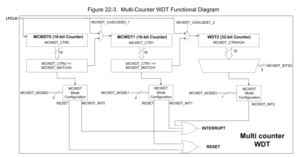
PSoC 6 Low Power MCWDT

Low Frequency Clock Sources (CLK_LF)

From the picture above you can see that the MCWDT uses the LFLK as the source clock for the counters.  Fortunately or unfortunately there is an inconsistency in the PSoC 63 TRM and PSoC Creator.  The PSoC Creator team decided to unify the names of all of the clocks by calling them all “Clk_*”.  Which is inconsistent with the TRM which calls it “LFLK”.  The LFCLK in the TRM is called the “Clk_LF” in the PSoC Creator GUIs and it is called “CLK_LF” or “ClkLf” in the firmware (confused yet?).  If not then you should be as I was the first time I saw it.

The Clk_LF can be driven by one of three source oscillators.  The PILO, ILO or the WCO.  Look at the upper left hand box where I have pulled down the selection menu.
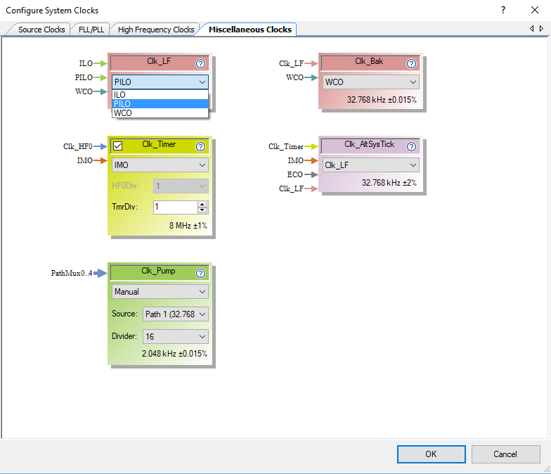
PSoC 6 Clock Configuration

But what is WCO, PILO and ILO?  These are clock sources which you can select the Clk_LF clock source on the “Source Clocks” page.  It can be:

  • The Internal Low Speed Oscillator (ILO) which is a super low power 32KHz RC Oscillator (but not very accurate)
  • The Precision Internal Low Speed Oscillator (PILO) is a more accurate, trim-able RC? oscillator, and presumably higher power (though I don’t know how much).
  • The Watch Crystal Oscillator (WCO) which is a very accurate crystal oscillator that gives you accurate timing at a higher power cost.

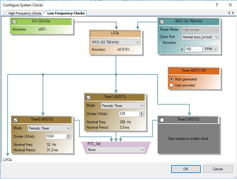
With the “Configure System Clocks” window in the DWR you can configure the behavior of the Clock Sources.  Notice that I have turned on all three of the Clock sources (ILO, PILO and WCO) something which you probably wouldn’t actually do.
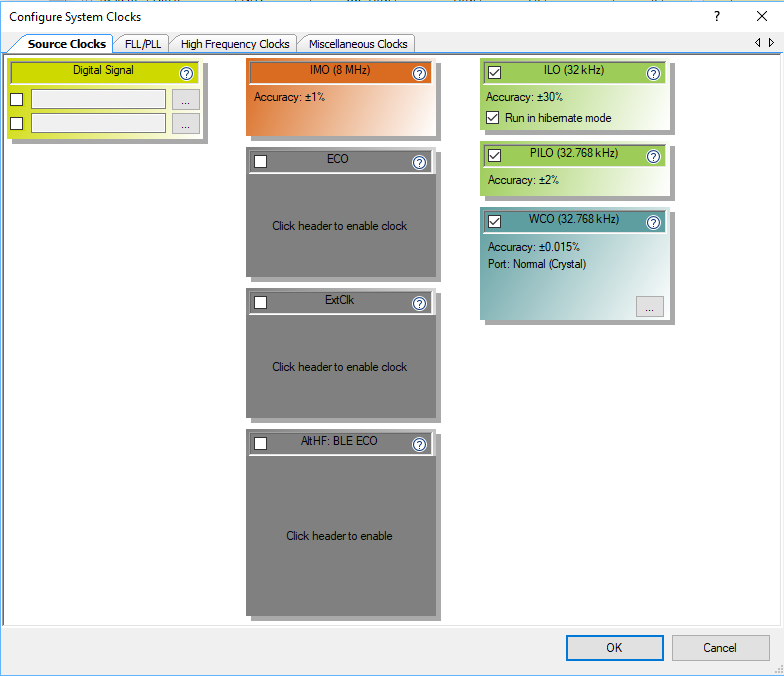
PSoC 6 Source Clock Configuration

When you click those buttons, PSoC Creator will create a function called “ClockInit” in the file “cyfitter_cfg.c” that is called by the PSoC startup code (and runs before your main() ).  You can see that the firmware enables the PILO and WCO (as well as the ILO which is on by default)

static void ClockInit(void)
{
	uint32_t status;

	/* Enable all source clocks */
	Cy_SysClk_PiloEnable();
	Cy_SysClk_WcoEnable(900u);
	Cy_SysClk_ClkLfSetSource(CY_SYSCLK_CLKLF_IN_PILO);

	/* Configure CPU clock dividers */
	Cy_SysClk_ClkFastSetDivider(0u);
	Cy_SysClk_ClkPeriSetDivider(1u);
	Cy_SysClk_ClkSlowSetDivider(0u);

Configuring the Clk_LF Source in Firmware

You can also configure the Clk_LF sources in your firmware.  In the firmware below, I check to see if the WCO is running.  If it is, then I set it to be the source of the Clk_LF.  If it is not running, then I try to start it.  And, finally, I print out the current source of the Clk_LF.

    // Is the Watch Crystal Osc running?
    if(Cy_SysClk_WcoOkay())
    {
        printf("Switching ClkLf to WCO\n");
        Cy_SysClk_ClkLfSetSource(CY_SYSCLK_CLKLF_IN_WCO);
    }
    else
    {
        printf("WCO Not functioning attempting a start\n");
        Cy_SysClk_WcoEnable(0); // come back immediately
        for(int i=0;i<100;i++) 
        {
            CyDelay(10);
            if(Cy_SysClk_WcoOkay())
            {
                printf("Suceeded in starting WCO in %dms\n",i*10);
                Cy_SysClk_ClkLfSetSource(CY_SYSCLK_CLKLF_IN_WCO);
                break;
            }
        }
        if(!Cy_SysClk_WcoOkay())
        {
            printf("Unable to start WCO in 1000ms\n");
        }
    }
                     
    // What is the clock source of the ClkLf?
    switch(Cy_SysClk_ClkLfGetSource ())
    {
        case CY_SYSCLK_CLKLF_IN_ILO:
            printf("Clk LF = ILO\n");
            break;
        case CY_SYSCLK_CLKLF_IN_ALTLF:
            printf("Clk LF = ALTLF\n");
        break;
        case CY_SYSCLK_CLKLF_IN_PILO:
            printf("Clk LF = PILO\n");
        break;
        case CY_SYSCLK_CLKLF_IN_WCO:
            printf("Clk LF = WCO\n");
        break;
    }

Overall Project Schematic Configuration

To demonstrate the PSoC 6 Low Power MCWDT, I start by creating a schematic.  It has the three color LEDs pins (RED, GREEN and BLUE), a UART to print out debugging information and finally the MCWDT connected to an interrupt.
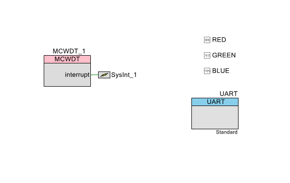
PSoC 6 Low Power MCWDT Schematic

The pin assignment is chosen to match the pins on my CY8CKIT-062-BLE Development kit. (look on the back)

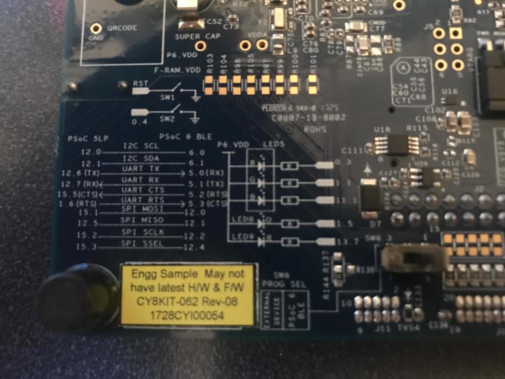
PSoC 6 Pin Configuration

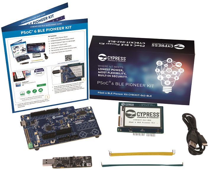
CY8CKIT-062-BLE

Configuring the Interrupts

When you place an interrupt component in PSoC Creator (which I did in the above schematic), it will then appear in the DWR on the interrupt page.  Here you can assign the interrupt to either of the MCU Cores, or I suppose both, though I think that is  probably a horrible idea.

PSoC Creators “fitter” sees that the interrupt is connected to a MCWDT.  It then does the job of attaching the interrupt to the correct interrupt number, in this case 19

PSoC 6 Interrupts

All the screen above does is create a little block of code in the firmware file cyfitter_sysint_cfg.c.  Look at the structure called cy_stc_sysint_t SysInt_1_cfg in the automatically generated code:

/*******************************************************************************
* File Name: cyfitter_sysint_cfg.c
* 
* PSoC Creator  4.2 Nightly Build 543
*
* Description:
* 
* This file is automatically generated by PSoC Creator.
*
********************************************************************************
* Copyright (c) 2007-2017 Cypress Semiconductor.  All rights reserved.
* You may use this file only in accordance with the license, terms, conditions, 
* disclaimers, and limitations in the end user license agreement accompanying 
* the software package with which this file was provided.
********************************************************************************/

#include "cyfitter_sysint.h"
#include "cyfitter_sysint_cfg.h"

/* ARM CM4 */
#if (((__CORTEX_M == 4) && (CY_CORE_ID == 0)))

    /* SysInt_1 */
    const cy_stc_sysint_t SysInt_1_cfg = {
        .intrSrc = (IRQn_Type)SysInt_1__INTC_NUMBER,
        .intrPriority = SysInt_1__INTC_CORTEXM4_PRIORITY
    };

    /* UART_SCB_IRQ */
    const cy_stc_sysint_t UART_SCB_IRQ_cfg = {
        .intrSrc = (IRQn_Type)UART_SCB_IRQ__INTC_NUMBER,
        .intrPriority = UART_SCB_IRQ__INTC_CORTEXM4_PRIORITY
    };

#endif /* ((__CORTEX_M == 4) && (CY_CORE_ID == 0)) */

So, where does SysInt_1__INTC_NUMBER get set?  That is done by the fitter in cyfitter_sysint.h.  Here is the automatically generated code:

/*******************************************************************************
* File Name: cyfitter_sysint.h
* 
* PSoC Creator  4.2 Nightly Build 543
*
* Description:
* 
* This file is automatically generated by PSoC Creator.
*
********************************************************************************
* Copyright (c) 2007-2017 Cypress Semiconductor.  All rights reserved.
* You may use this file only in accordance with the license, terms, conditions, 
* disclaimers, and limitations in the end user license agreement accompanying 
* the software package with which this file was provided.
********************************************************************************/

#ifndef INCLUDED_CYFITTER_SYSINT_H
#define INCLUDED_CYFITTER_SYSINT_H
#include "cy_device_headers.h"

/* SysInt_1 */
#define SysInt_1__INTC_CORTEXM4_ASSIGNED 1
#define SysInt_1__INTC_CORTEXM4_PRIORITY 7u
#define SysInt_1__INTC_NUMBER 19u
#define SysInt_1_INTC_CORTEXM4_ASSIGNED 1
#define SysInt_1_INTC_CORTEXM4_PRIORITY 7u
#define SysInt_1_INTC_NUMBER 19u

/* UART_SCB_IRQ */
#define UART_SCB_IRQ__INTC_CORTEXM4_ASSIGNED 1
#define UART_SCB_IRQ__INTC_CORTEXM4_PRIORITY 7u
#define UART_SCB_IRQ__INTC_NUMBER 46u
#define UART_SCB_IRQ_INTC_CORTEXM4_ASSIGNED 1
#define UART_SCB_IRQ_INTC_CORTEXM4_PRIORITY 7u
#define UART_SCB_IRQ_INTC_NUMBER 46u

#endif /* INCLUDED_CYFITTER_SYSINT_H */

To make all of this work, you simply need to install the interrupt handler by calling Cy_SysInt_Init in your main.c.

    // install ISR...
    Cy_SysInt_Init(&SysInt_1_cfg,myWDT);
    NVIC_EnableIRQ(SysInt_1_INTC_NUMBER);

Configuring the PSoC 6 Low Power MCWDT with the GUI

As with all (or almost all) PSoC components, you can configure them in the GUI.  In the picture below you can see that you can set

  1. Enable/Disable
  2. The Match Value
  3. The Mode (interrupt, watchdog, none)
  4. Free Running or Clear on Match
  5. The Cascade (meaning connect the counters together)
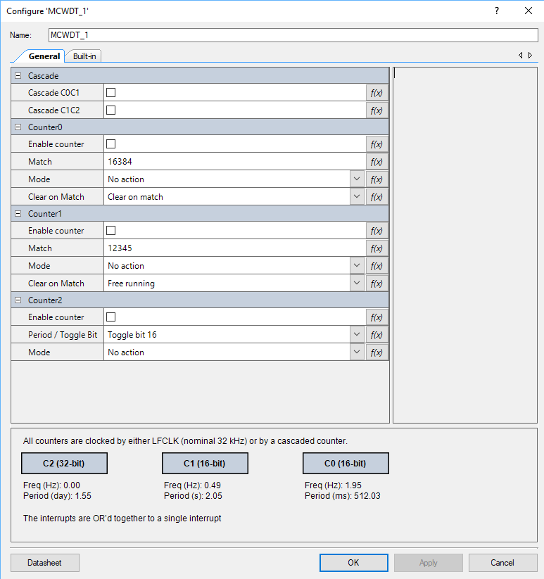
PSoC 6 Low Power MCWDT Configuration GUI

All of those configuration items will end up in the file MCWDT_1_PDL.c in a structure that looks like this:

/** The instance-specific configuration structure. This should be used in the 
*  associated MCWDT_1_Init() function.
*/ 
const cy_stc_mcwdt_config_t MCWDT_1_config =
{
    .c0Match     = MCWDT_1_C0_MATCH,
    .c1Match     = MCWDT_1_C1_MATCH,
    .c0Mode      = MCWDT_1_C0_MODE,
    .c1Mode      = MCWDT_1_C1_MODE,
    .c2ToggleBit = MCWDT_1_C2_PERIOD,
    .c2Mode      = MCWDT_1_C2_MODE,
    .c0ClearOnMatch = (bool)MCWDT_1_C0_CLEAR_ON_MATCH,
    .c1ClearOnMatch = (bool)MCWDT_1_C1_CLEAR_ON_MATCH,
    .c0c1Cascade = (bool)MCWDT_1_CASCADE_C0C1,
    .c1c2Cascade = (bool)MCWDT_1_CASCADE_C1C2
};

Then you can either call the MCWDT_1_Start() function or you can call the PDL function Cy_MCWDT_Init(&MCWDT_1_config);

PSoC 6 Low Power MCWDT Firmware

You can also configure the PSoC 6 Low Power MCWDT in your firmware as I have done below:

   Cy_MCWDT_Unlock(MCWDT_STRUCT0);
    // Turn off all of the counters
    Cy_MCWDT_Disable(MCWDT_STRUCT0,CY_MCWDT_CTR0 | CY_MCWDT_CTR1 | CY_MCWDT_CTR2,100);
    Cy_MCWDT_ResetCounters(MCWDT_STRUCT0,CY_MCWDT_CTR0,100);
    Cy_MCWDT_ResetCounters(MCWDT_STRUCT0,CY_MCWDT_CTR1,100);
    
    Cy_MCWDT_SetMode(MCWDT_STRUCT0,0,CY_MCWDT_MODE_NONE); // 0=Counter 0
    Cy_MCWDT_SetMode(MCWDT_STRUCT0,1,CY_MCWDT_MODE_INT);  // 1=Counter 1
    
    Cy_MCWDT_SetCascade(MCWDT_STRUCT0,CY_MCWDT_CASCADE_C0C1 );
    
    Cy_MCWDT_SetInterruptMask(MCWDT_STRUCT0,CY_MCWDT_CTR1); // Only take ints from counter 1
    
    // delay = 32768*16 = 8 seconds & 32khz
    Cy_MCWDT_SetMatch(MCWDT_STRUCT0,0,32768,100);
    Cy_MCWDT_SetMatch(MCWDT_STRUCT0,1,16,100);
       
    Cy_MCWDT_SetClearOnMatch(MCWDT_STRUCT0,0,1);
    Cy_MCWDT_SetClearOnMatch(MCWDT_STRUCT0,1,1);
    
    Cy_MCWDT_Enable(MCWDT_STRUCT0,CY_MCWDT_CTR0|CY_MCWDT_CTR1,100);

The Interrupt Service Routine (ISR) for the MCWDT is pretty simple.  It just reads the cause of the interrupt, which could be any one of the counters in the MCWDT (or more than one of them).  Then it inverts either the Red, Green or Blue LED.  And finally it clears the interrupt source inside of the MCWDT.

void myWDT(void)
{
    uint32_t cause;
    cause = Cy_MCWDT_GetInterruptStatusMasked(MCWDT_STRUCT0);
    if(cause & CY_MCWDT_CTR0)
    {
        Cy_GPIO_Inv(RED_PORT,RED_NUM);
    }
    
    if(cause & CY_MCWDT_CTR1)
    {
        Cy_GPIO_Inv(GREEN_PORT,GREEN_NUM);
    }
    
    if(cause & CY_MCWDT_CTR2)
    {
        Cy_GPIO_Inv(BLUE_PORT,BLUE_NUM);
    }
    
    Cy_MCWDT_ClearInterrupt(MCWDT_STRUCT0,cause);
}

When I run this program I get a slowly blinking Green LED in Low Power mode:
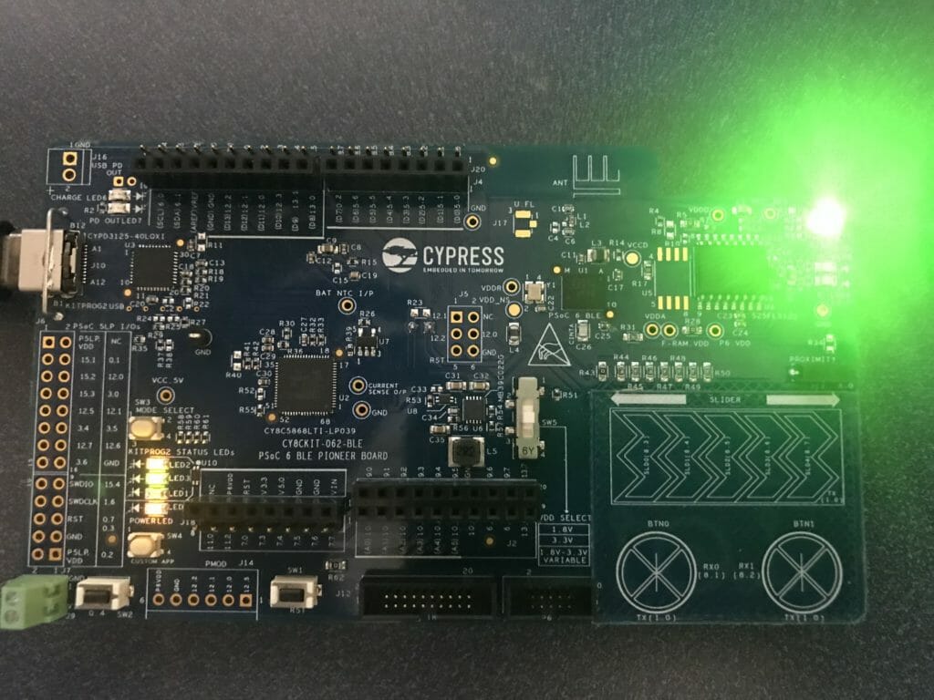
PSoC 6 Low Power MCWDT

PSoC 4200M Low Power with WDTs

Summary

The last few weeks of my technical life have been frustrating.  Nothing and I mean nothing has been easy.  A few weeks ago I replied to a comment about cascading the watch dog timers in the PSoC 4200M to extend the sleep time – the article was called “PSoC 4200M WDT Long Deep Sleep“.  I wanted to measure power to see what exactly was happening.  But the great technical gods were conspiring against me and I had tons of problems.  Well I have things sorted out.  In this article I will build a project using the PSoC 4200M Watch Dog Timers and show the power measurements on the CY8CKIT-043 and CY8CKIT-044.  I will include PSoC 4200M low power measurements at 5V and 3.3V as well as with both the ILO and the WCO as the source of the WDT.  To do this I:

  1. Created a PSoC 4200M low power project
  2. Modified the CY8CKIT-043M
  3. Reject the Fluke 175
  4. Read the Keysite 34465A Multimeter Manual
  5. PSoC 4200M Low Power Current Measurement

PSoC 4 Low Power Firmware

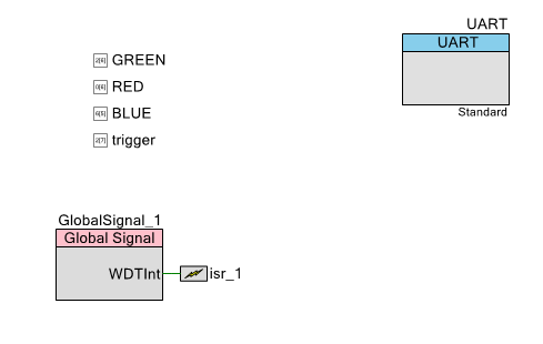
First I create a schematic.  This includes 4 digital output pins.  The GREEN, RED and BLUE are attached to the tri-color LED.  A UART to print the status of the startup.  And an interrupt connected to the WDT Interrupt.

PSoC 4200M Low Power Schematic

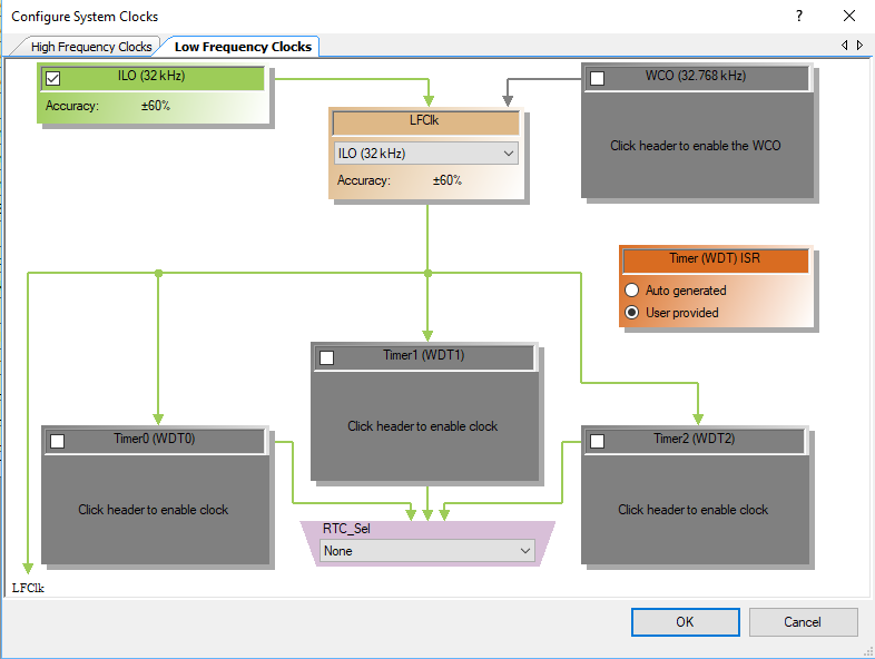
The next thing to do is to make sure that the WDT is being driven by the ILO.  I also turn off the three WDTs because I will configure them in the firmware.

PSoC 4200M Low Power Clock Configuration

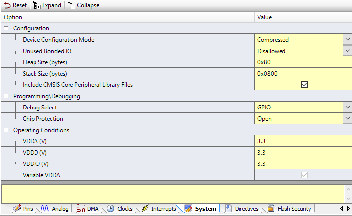
In order to get low power you need to switch the debugging pins off i.e. make them GPIOs.  You can do this on the DWR System Screen.

Finally write some firmware.  The firmware simply

  1. Blinks the LED 10 times
  2. Prints “Started” to the UART, waits until the buffer is flushed, then turns off the UART to make sure the power is low.
  3. Configure the Watch Dog Timers.  This could have been done on the Low Frequency Clock Screen (except for the cascading of timers which had to be done with firmware)
  4. Turn off the Pin, Deep Sleep the chip… and wait.  When an interrupt from the WDT occurs, it calls the ISR (next section)
int main(void)
{
    trigger_Write(1); // Measure Startup

    // Blink the LED when the PSoC Starts
    for(int i=0;i<10;i++)
    {
        BLUE_Write(~BLUE_Read());
        CyDelay(200);
    }
    BLUE_Write(0);
    
    UART_Start();
    UART_UartPutString("Started\n");
    isr_1_StartEx(wdtInterruptHandler);

    while(UART_SpiUartGetTxBufferSize()); // Wait until the UART has flushed - then turn off the power
    UART_Stop();

    CySysWdtUnlock(); // Enable modification of the WDT Timers
    
    // Turn off the WDTs (all three of them)
    CySysWdtDisable(CY_SYS_WDT_COUNTER0_MASK); 
    CySysWdtDisable(CY_SYS_WDT_COUNTER1_MASK);
    CySysWdtDisable(CY_SYS_WDT_COUNTER2_MASK);
    
    // Make Timer 0 & 1 run with no interrupt, and 2 cause an interrupt
    CySysWdtSetMode(CY_SYS_WDT_COUNTER0,CY_SYS_WDT_MODE_NONE);
    CySysWdtSetMode(CY_SYS_WDT_COUNTER1,CY_SYS_WDT_MODE_NONE);
    CySysWdtSetMode(CY_SYS_WDT_COUNTER2,CY_SYS_WDT_MODE_INT);
    
    // Set the time to 32768/(64*64*2^6) = 32768/(2^18) = 0.125 = 1/8 Hz
    CySysWdtSetMatch(CY_SYS_WDT_COUNTER0, 64);
    CySysWdtSetMatch(CY_SYS_WDT_COUNTER1, 64);
    CySysWdtSetToggleBit(6);
    
    CySysWdtSetClearOnMatch(CY_SYS_WDT_COUNTER0,1); // When counter his period reset counter
    CySysWdtSetClearOnMatch(CY_SYS_WDT_COUNTER1,1);

    CySysWdtSetCascade(CY_SYS_WDT_CASCADE_01 | CY_SYS_WDT_CASCADE_12); // Cascade 0-1-2
    CySysWdtEnable(CY_SYS_WDT_COUNTER0_MASK | CY_SYS_WDT_COUNTER1_MASK | CY_SYS_WDT_COUNTER2_MASK );
    
    trigger_Write(0); // End measurement

    CyGlobalIntEnable; /* Enable global interrupts. */
    
    for(;;)
    {
        trigger_Write(0); // setup trigger
        CySysPmDeepSleep(); // wait for interrupt in deep sleep
    }
}

The ISR first turns on the trigger pin (which I will use in the next article to trigger the oscilloscope).  Then it determines which timer caused the interrupt.  Originally I was blinking different color LEDs when I was trying to figure out what was happening.  With the current configuration WDT0 and WDT1 will never trigger an interrupt.  Finally it clears the interrupt and returns.  When it returns the main loop will turn off the trigger pin and then deep sleep.

void wdtInterruptHandler()
{
    trigger_Write(1); // Chip is woken up 
    uint32 reason = CySysWdtGetInterruptSource();
    
    if(reason & CY_SYS_WDT_COUNTER0_INT)
        RED_Write(~RED_Read());
  
    if(reason & CY_SYS_WDT_COUNTER1_INT)
        GREEN_Write(~GREEN_Read());
  
    if(reason & CY_SYS_WDT_COUNTER2_INT)
        BLUE_Write(~BLUE_Read());
  
    CySysWdtClearInterrupt(reason);  // Clear the WDT Interrupt
}

Modified the CY8CKIT-043

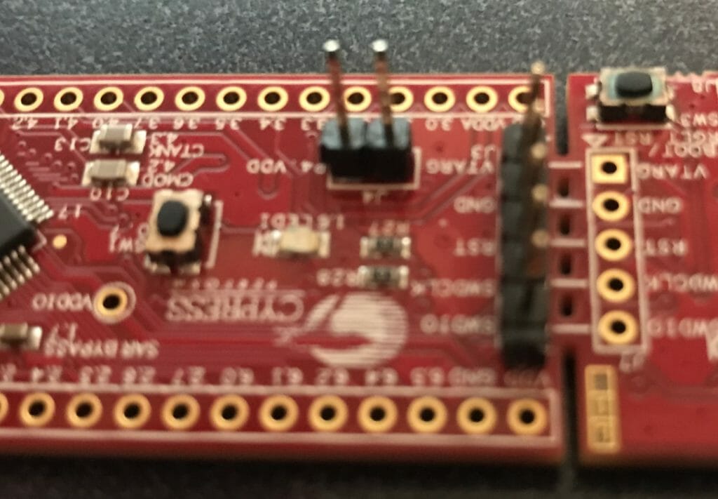
In order to measure current with the. CY8CKIT-043 you need to remove the 0 ohm resistor R22 and install a jumper (J4) so that you can measure the current into the board.

CY8CKIT-043 Schematic

R22 is on the back of the development kit.  You can see that I circled it.

CY8CKIT-042 modification for PSoC 4200M Low Power Measurement

Then install a jumper into J4. I  just use a two pin break away header.

CY8CKIT-042 modification for PSoC 4200M Low Power Measurement

Fluke 175

According to the AN 86233 PSoC® 4 and PSoC Analog Coprocessor Low-Power Modes and Power Reduction Techniques I should be able to get 1.3uA in deep sleep 1.3mA in active.

PSoC 4200M Low Power Specs

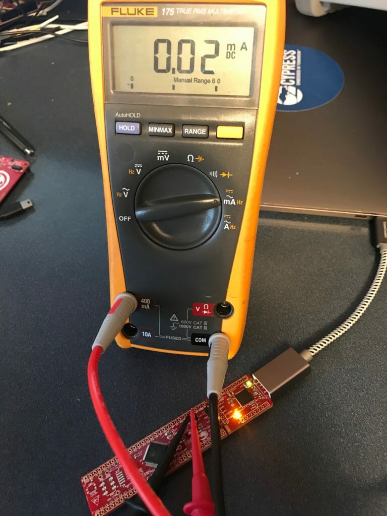
I started with my trusty Fluke 175… but quickly realized that uA are not in the cards.  It appears that the lowest it can measure is 10’s of microamps.

PSoC 4200M Low Power Measurement with Fluke

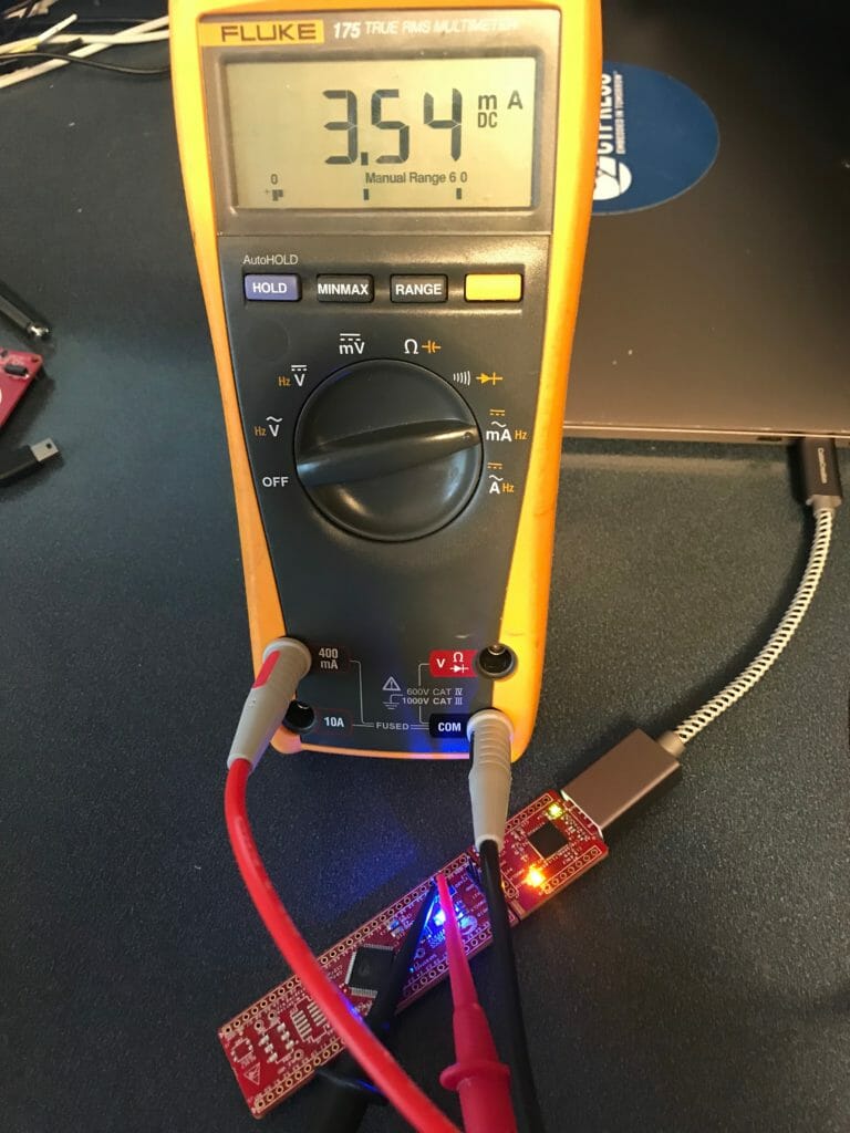
It does fine with the active mode.

PSoC 4200M Low Power Measurement with Fluke

Keysight 34465A 6 1/2 Digit Multimeter

The good news is that I also have a Keysight 34465A 6/12 digit multimeter.  In the 1uA range it can measure +- 0.055% of 1uA or about 5nA (is that right?)

Keysight 34655A Specs

Keysight 34665A Current Measurement Ranges

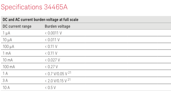
It also doesnt change the input power supply very much.  In fact only 0.0011v in 3.3v is negligible.

Keysight 34465A Drop Out Voltage

PSoC 4200M Low Power Current Measurement

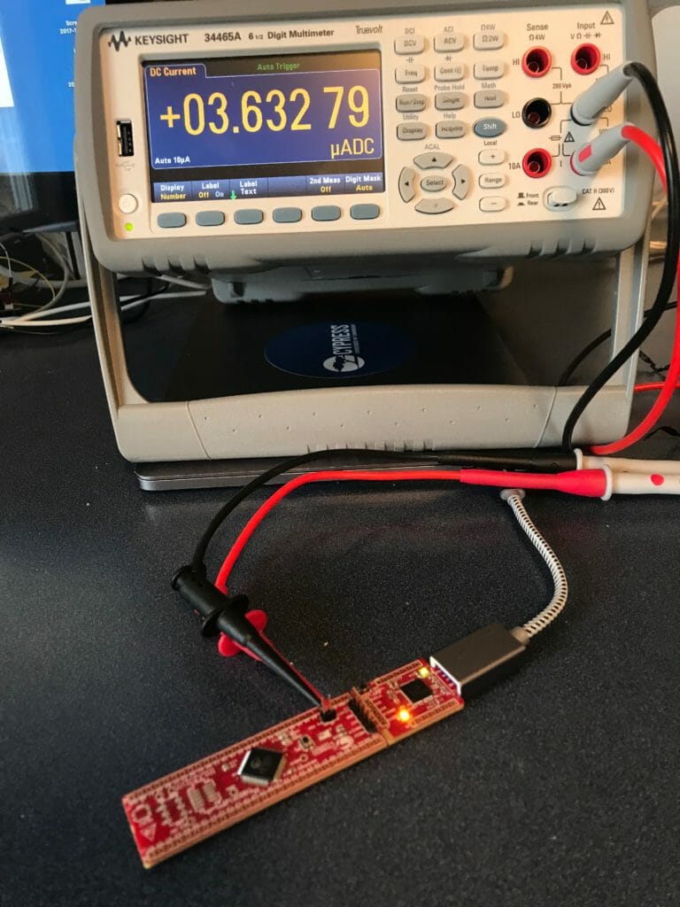
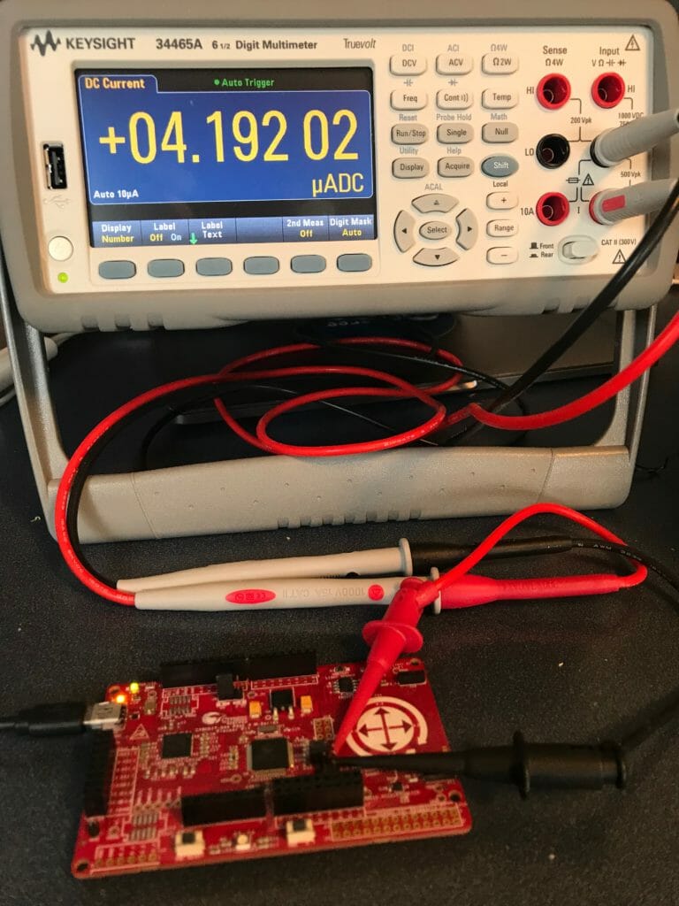
I wanted to measure Active, Sleep, Deep Sleep on the CY8CKIT-043 and CY8CKIT-44 with the WCO on and off.  In the two pictures below you can see that the system is taking between 3.6uA and 4.2uA in Deep Sleep.

PSoC 4200M Low Power Measurement

PSoC 4200M Low Power Measurement

Here are tables with all of the measurements.

5V – CY8CKIT-044

Mode WCO On WCO Off
Active 12..860mA 12.859mA
Sleep 5.339mA 5.335mA
Deep Sleep 4.206uA 1.078uA

3.3V – CY8CKIT-044

Mode WCO On WCO Off
Active 12.84mA 12.84mA
Sleep 5.328mA 5.327mA
Deep Sleep 4.096uA 0.940uA

5V – CY8CKIT-043

Mode WCO Off
Active 12.711mA
Sleep 5.352mA
Deep Sleep 3.632uA

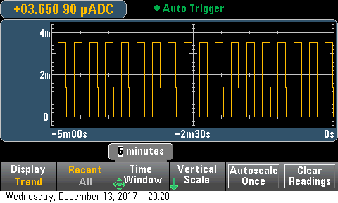
The other thing that is pretty cool with the KeySite is that you can put it into “Trend” mode and it can display the current readings over a long period.  In the picture below I am flashing the LED which takes around 3.5mA @ 3.3v on this development kit.

PSoC 6, FreeRTOS & SSD1306 OLED Display

Summary

This week I have been working with my friend Hassane El Khoury on his hobby project which has the SSD1306 in it. [if you want to know more about the project, leave a comment and maybe he will answer the question].  I have been helping him get a number of things going including this display which I have written about before.  This article describes the integration of the SSD1306 OLED Display into his project with the PSoC 6 & FreeRTOS.

Firmware Architecture

Hassane started his career as an Automotive System Designer, then he worked as an Applications Engineer, so he has “mad” skills in this area.  He is building his project with a PSoC 6 and is heavily using FreeRTOS (which is new for him).  He has been distracted with some other thing the last few years, so I have been serving as a consultant on the latest PSoC stuff to smooth the learning curve.  In this case PSoC6, FreeRTOS and the SSD1306 OLED Display.  I have only used the SSD1306 OLED Display with PSoC 4 and WICED, but I ASSUMED (incorrectly assumed… which I will talk about in the next article) that there would be no problems making it work in that environment.

Hassane is all about reuse and he had copied the design of this section of his project from my article on using queues with FreeRTOS.  It looks like this.

  1. There is a task that manages the I2C and talks directly to the SCB hardware and the I2C devices
  2. There is a task that manages the OLED

ssd1306 oled display architecture

Originally the OLED task was talking directly to the I2C via the SCB (the red line on the picture).  Remember from the article on the U8G2 library, the hardware abstraction layer looks like this.  Basically it

  1. Sends an I2C Start at the start of the U8G2 transaction
  2. Sends an I2C Stop at the end of the tranaction
  3. Send the number of bytes called for.
uint8_t u8x8_I2C_HW(u8x8_t *u8x8, uint8_t msg, uint8_t arg_int, void *arg_ptr)
{
    uint8_t *data;
    switch(msg)
    {
        case U8X8_MSG_BYTE_SEND:            
            data = (uint8_t *)arg_ptr;
            while( arg_int > 0 )
            {
                Cy_SCB_I2C_MasterWriteByte(I2Cm1_HW, *data, I2C_TIMEOUT, &I2Cm1_context);
  	            data++;
	            arg_int--;
            }
        break;
      
        case U8X8_MSG_BYTE_START_TRANSFER:
            Cy_SCB_I2C_MasterSendStart(I2Cm1_HW, u8x8_GetI2CAddress(u8x8)>>1, CY_SCB_I2C_WRITE_XFER, I2C_TIMEOUT, &I2Cm1_context);
         break;
        
        case U8X8_MSG_BYTE_END_TRANSFER:
            Cy_SCB_I2C_MasterSendStop(I2Cm1_HW, I2C_TIMEOUT, &I2Cm1_context);
        break;
    
        default:
            return 0;
    }
    
    return 1;
}

The problem with this design is that it takes over the I2C hardware and requires exclusive control.  Moreover, it leaves you program hung while the transaction is happening.  To solve this problem, there are three options

  1. “Assign” the SCB block to the exclusive use of this task (makes it hard to share with other I2C devices)
  2. Create a mutex for the SCB.  This will work, but it will not allow the task to “queue” transactions and move on
  3. Create a task to manage the SCB with a queue (the option that Hassane chose)

The I2C message queue holds complete transactions.  Each transaction (which he called I2Cm_transaction_t) looks like this:

typedef enum I2Cm_transactionMethod {
    I2CM_READ,
    I2CM_WRITE
} I2Cm_transactionMethod_t;

typedef enum I2Cm_registerAddresType {
    I2CM_NONE, 
    I2CM_BIT8,
    I2CM_BIT16
} i2cm_registerAddressType_t;

typedef struct I2Cm_transaction {
    I2Cm_transactionMethod_t I2Cm_method;        // I2CM_READ or I2CM_WRITE
    uint8_t I2Cm_address;                        // The I2C Address of the slave
    i2cm_registerAddressType_t I2Cm_regType;     // I2CM_8BIT or I2CM_16BIT
    uint16_t I2Cm_register;                      // The register in the slave    
    uint8_t *I2Cm_bytes;                         // A pointer to the data to be written (or a place to save the data)
    uint32_t *I2Cm_bytesProcessed;               // A return value with the number of bytes written
    uint32_t I2Cm_byteNum;                       // How many bytes are in the request
    SemaphoreHandle_t I2Cm_doneSemaphore;        // If you want a semaphore flagging that the transaction is done 
} I2Cm_transaction_t;

In order to fix the the HAL you just sets up a transaction at the start of the task:

   memset(&OLEDtransaction,0,sizeof(OLEDtransaction));
	OLEDtransaction.I2Cm_method = I2CM_WRITE;
	OLEDtransaction.I2Cm_address = OLED_ADDRESS_1;
	OLEDtransaction.I2Cm_regType = I2CM_NONE;
	OLEDtransaction.I2Cm_bytes = buff;
	OLEDtransaction.I2Cm_bytesProcessed = &numProcessed;	
    OLEDtransaction.I2Cm_doneSemaphore = xSemaphoreCreateBinary();

Then queue up the bytes into a buffer, and flush the buffer when the “U8X8_MSG_BYTE_END_TRANSFER” message comes

uint8_t u8x8_I2C_HW(u8x8_t *u8x8, uint8_t msg, uint8_t arg_int, void *arg_ptr)
{
    uint8_t *data;
    switch(msg)
    {
        case U8X8_MSG_BYTE_SEND:        
            data = (uint8_t *)arg_ptr;
            while( arg_int > 0 )
            {
                buff[buffCount] = *data;
                buffCount += 1;
                CY_ASSERT(buffCount < BUFFSIZE);              
  	            data++;
	            arg_int--;
            }
        break;
 
        case U8X8_MSG_BYTE_START_TRANSFER:
            buffCount = 0;
         break;
        
        case U8X8_MSG_BYTE_END_TRANSFER:
	        OLEDtransaction.I2Cm_byteNum = buffCount;
            I2Cm1RunTransaction(&OLEDtransaction);
        break;
    
        default:
        return 0;
    }
    
    return 1;
}

SSD1306 OLED Display

Now, the short block of test code works perfect:

    u8x8_Setup(&MyI2Cu8x8, u8x8_d_ssd1306_128x32_univision, u8x8_cad_ssd13xx_i2c, u8x8_I2C_HW, u8x8_gpio_and_delay_PSoC6);
        
    u8x8_InitDisplay(&MyI2Cu8x8);  
    u8x8_SetPowerSave(&MyI2Cu8x8,0);
    u8x8_ClearDisplay(&MyI2Cu8x8);
    u8x8_SetFont(&MyI2Cu8x8,u8x8_font_amstrad_cpc_extended_f);
    u8x8_DrawString(&MyI2Cu8x8,0,0," Killer Mustang ");
    u8x8_DrawString(&MyI2Cu8x8,0,1,"   Test OLED    ");
    u8x8_DrawString(&MyI2Cu8x8,0,2,"________________");

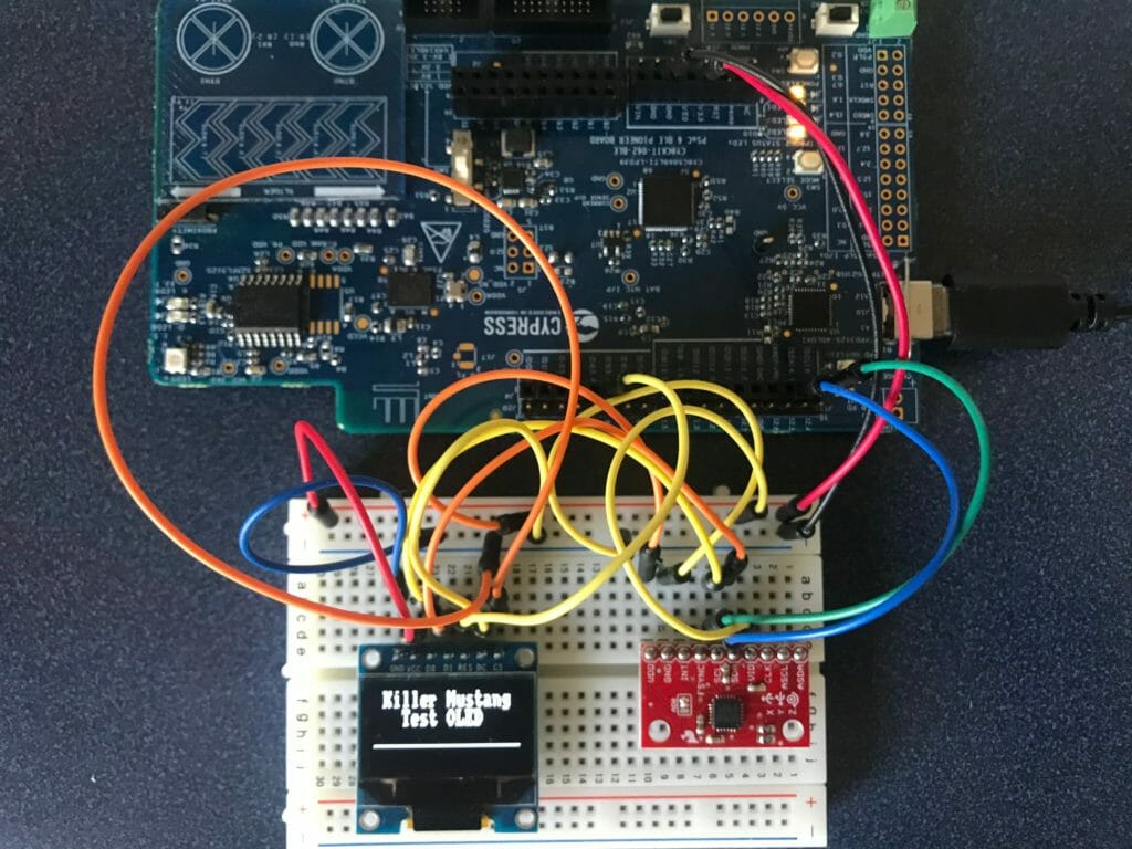
And I get a nice output (I wonder what a “Killer Mustang” is?)

In the next article Ill talk about the SS1306 and a problem that I created for myself.

EEWeb – IoT Expert Site of the Day

This morning I was looking around on the Web… and look what I found,  IoT Expert was site of the day with EEWeb yesterday.  How cool is that?  I had been trading email with Aubrey Kagan about getting this arranged – so thank you Aubrey.

EEWeb is a super cool website thas a lot gong on.  There are articles and example projects, a lot of similar to stuff to what I do. I got introduced to EEWeb earlier this year by a friend of mine, Adam Carlson (the editor) who I met face to face earlier this  year at a Maker Faire.

What I didn’t realize (though it should have been obvious) was this website was the spawn of EETimes, which was for years the classic industry publication.

Here are two screen shots.

IoTExpert on EEWEB


IoTExpert on EEWEB


PSoC 4200M WDT Long Deep Sleep

Summary

Earlier this year I wrote an article about using the PSoC 4200M WDT Watch Dog Timers.  In it I described a bunch of things that you could do with the PSoC 4200M WDT to help you time events, reset the part etc.  Recently a user named JAGIR asked if I could generate interrupts slower than 2 seconds and have the PSoC 4200M in deep sleep.  The answer to both of those questions is yes.

In order to make this work you need to “cascade” two WDTs together, something you can only do with firmware.  I have updated my previous workspace with a new project called “LongDeepSleep” which you can “Git” on my GitHub website or you can “git@github.com:iotexpert/PSoC4-WDTExamples.git”

Configure the PSoC 4200M WDT Design

First add a digital output pin called “RED” to the schematic

PSoC 4200M WDT Schematic

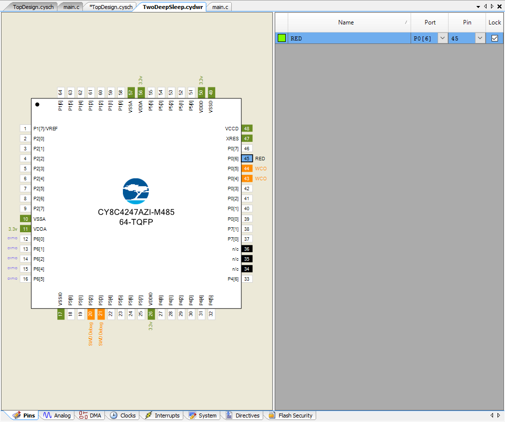
Then assign it to P0[6]

PSoC 4200M WDT - DWR Pin Assignment

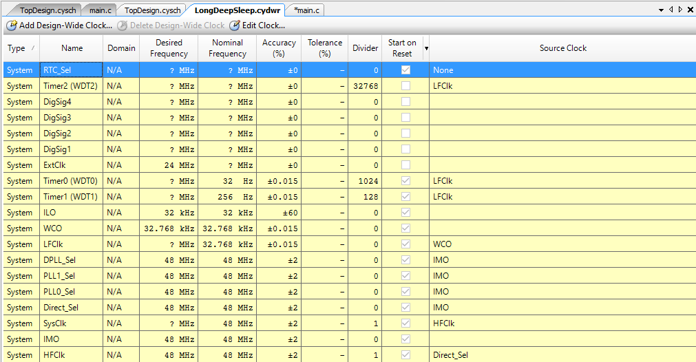
Go to the clocks tab of the design wide resources.  Then click on “Edit Clock”.

PSoC 4200M WDT Clocks

On the Low Frequency Clocks configuration page of the design wide resources turn on the two WDTs and setup the dividers.

PSoC 4200M WDT

System Reference Guide – PSoC 4200M WDT

All of the documentation for the PSoC 4200M WDT is in the “Low Frequency Clock aka cy_lfclk” of the system resources documentations.

PSoC 4200M WDT System Reference Guide

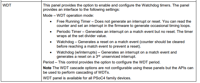
When you read a little bit down in the PSoC 4 Low Frequency clock documentation you will find “Note The EDT cascade options are not configurable using these panels but the APIs can be used to perform cascading of WDTs”

PSoC 4200M WDT

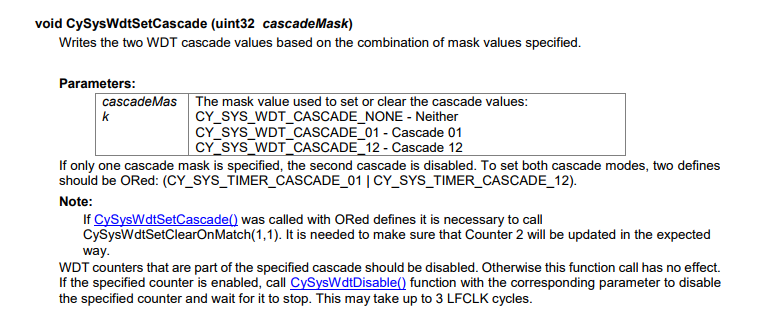
Then you search a little bit further down in the document and you will find the API CySysWDTSetCascade which will allow you to hook multiple 16-bit counters together to get 32 or more bits.

PSoC 4200M WDT - CySysWdtSetCascade

Write the PSoC 4200M WDT Firmware

The first example will blink the LED every 4 seconds.  Remember from the configuration above it has a 32KHz input clock with a divider of 1024 on WDT0 and a divider of 128 on WDT1.  That means you will get 32KHz / (1024 *128) = 0.25 Hz aka every 4 seconds.

#include "project.h"

void wdtCallback()
{
    RED_Write(~RED_Read());
    
}

int main(void)
{
    CyGlobalIntEnable; /* Enable global interrupts. */
    CySysWdtSetInterruptCallback(CY_SYS_WDT_COUNTER1,wdtCallback);
    CySysWdtSetCascade(CY_SYS_WDT_CASCADE_01);
    
    for(;;)
    {
        CySysPmDeepSleep();
    }
}

You can also get different delays by changing the dividers using firmware.  In the example below it is 1Hz output.

#include "project.h"

void wdtCallback()
{
    RED_Write(~RED_Read());
}

int main(void)
{
    CyGlobalIntEnable; /* Enable global interrupts. */
    CySysWdtSetInterruptCallback(CY_SYS_WDT_COUNTER1,wdtCallback);
    CySysWdtSetCascade(CY_SYS_WDT_CASCADE_01);
    
    CySysWdtSetMatch(0,512);
    CySysWdtSetMatch(1,64);
    // Total divide = 512*64 = 32768 
    
    for(;;)
    {
        CySysPmDeepSleep();
    }
}


PSoC 6 Introduction – Behind the Scenes

Summary

As you might have noticed, last week I did a bunch of work creating a live streaming video series about PSoC 6.  You can find the recorded video here.  If you have been living under a bridge you might not know that PSoC 6 is the new Cypress PSoC.  It includes a dual ARM Cortex M4/M0+, a Bluetooth Low Energy 5.0 Radio, CapSense plus all of the other stuff that PSoC is known for.  The chip is super cool and has gotten everybody and their brother excited about the future.

PSoC 6 Introduction

# Title Comment
0 A Two Hour PSoC 6 Class An introduction to the PSoC 6 class with links to all of the documents
1 Resources Links to all of the Cypress PSoC 6 information including videos, application notes etc.
2 Your First Project Learn how to build a PSoC 6 project and program your CY8CKIT-062-BLE development kit
3 FreeRTOS and a Debugging UART Build a project using FreeRTOS including a debug console with the UART
4 CapSense Build a project using the Mutual Cap Buttons and Self Cap Slider
5 Bluetooth Low Energy Build a CapSense project using BLE and CySmart

Since I did the webinar several things have happened

  1. Lesson 4: I fixed an error in the stack size for FreeRTOS
  2. Lesson 5: The PSoC Creator BLE PDL has been upgraded to greatly simplify the notifyCapSense function

All of the projects are available at git@github.com:iotexpert/psoc-6-introduction.git or www.github.com/iotexpert/psoc-6-introduction

You will be seeing a bunch more from me using the CY8CKIT-062-BLE development kits.

PSoC 6 Webinar

Here are some behind the scenes pictures that were taken the day before and the day of the recording session.

In the studio on Wednesday night… why doesnt it work?

Getting Ready for the PSoC 6 Webinar

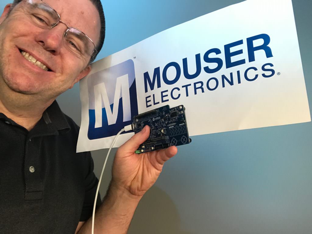
Yes, Mouser was sponsoring the event… thank you very much!

PSoC 6 and Mouser

Getting things setup the morning of the recording session.

The morning of the PSoC 6 Video Webinar

During the presentation (Im sure whatever I was saying was important)

Talking about PSoC 6

Some video taken from behind the scenes.

The Gospel of PSoC 6

The whole crew.  Thank you very much to Mouser and ON24.

The whole crew for the PSoC 6 Webinar

Lesson 5 – PSoC 6 Introduction: Bluetooth Low Energy

PSoC 6 Introduction

# Title Comment
0 A Two Hour PSoC 6 Class An introduction to the PSoC 6 class with links to all of the documents
1 Resources Links to all of the Cypress PSoC 6 information including videos, application notes etc.
2 Your First Project Learn how to build a PSoC 6 project and program your CY8CKIT-062-BLE development kit
3 FreeRTOS and a Debugging UART Build a project using FreeRTOS including a debug console with the UART
4 CapSense Build a project using the Mutual Cap Buttons and Self Cap Slider
5 Bluetooth Low Energy Build a CapSense project using BLE and CySmart

Since I did the webinar several things have happened

  1. Lesson 4: I fixed an error in the stack size for FreeRTOS
  2. Lesson 5: The PSoC Creator BLE PDL has been upgraded to greatly simplify the notifyCapSense function

All of the projects are available at git@github.com:iotexpert/psoc-6-introduction.git or www.github.com/iotexpert/psoc-6-introduction

Project Description

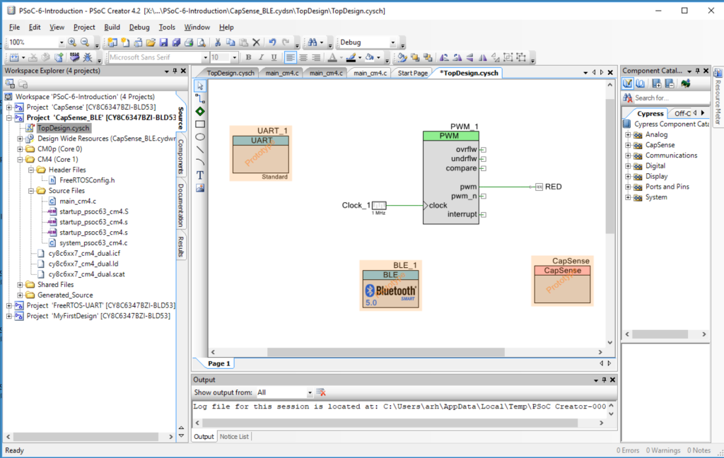
This project is a PSoC 6 BLE extension of the previous project with CapSense and UART.

The BLE will:

  • Advertise the device with the name “P6Intro” and as having the CapSense Service
  • Will allow one connection (with no security)
  • A BLE CapSense Service with the CapSense Slider characteristic as “notify”
  • When the CapSense slider updates it will send a notification to any connected device

The CapSense will (same as before)

  • BTN0 will set the intensity to 0%
  • BTN1 will set the intensity to 100%
  • CapSense slider will set the intensity (0-100) when touched

The UART will (same as before)

  • UART Key ‘0’ turn the LED to intensity = 0%
  • UART Key ‘1’ turn the LED to intensity = 100%
  • UART Key ‘5’ turn the LED to intensity = 50%
  • UART Key ‘?’ will printout help

How does it work?

This device will act as a GAP Peripheral with a GATT database server with the CapSense Service.  The PSoC 6 BLE component will allow you to split the BLE function onto the CM0+ (Controller) and the CM4 (Host and Profiles).  On the CM4 you will build an event handler which will act each time something happens in the Bluetooth world e.g. a connection, a disconnection, a read or write.

(same as previous project) You can control the intensity of an LED with a pulse width modulator and a high frequency input clock.  If the duty cycle is “small” then the intensity of the LED is low (meaning dim).  If the duty cycle is “big” then the intensity is “high”.  A 0% duty cycle will be off, a 50% duty cycle will be in the middle and 100% duty cycle will be all on.  To make this work I will set the input clock to 1 MHZ and the PWM Period to 100.  The PWM Compare value will then be set between 0 and 100 to represent brightness in percent.

(same as previous project) The Cypress CapSense block has two sensing modes, mutual capacitance and self-capacitance.   The CY8CKIT-062-BLE has two Mutual Capacitance buttons and a 5-Segment Self or Mutual Capacitance Slider.

The project will have four tasks

  • BLE – Will act as a BLE GATT Peripheral that advertises the CapSense Service with the CapSense Slider.  The value of the slider will ‘Notify’
  • UART – Read data from the keyboard and send messages to the PWM Task
  • CapSense – Read finger positions from the slider and buttons and send messages to the PWM Task
  • PWM – Will have an input queue, when a integer message is received it will set the PWM compare value to the integer received (0 >= msg <= 100)

How am I going to do it?

  1. Copy, Paste and Rename the CapSense UART Project
  2. Add and Configure the BLE Component
  3. Fix the Interrupts
  4. Update the main_cm0p. c to run the BLE radio
  5. Add three global variables to main_cm4.c
  6. Create a new task to process the BLE
  7. Create an Event Handler
  8. Make a Function to Send Notifications
  9. Update the capSenseTask to Send Values
  10. Add the bleTask to main function in main_cm4.c
  11. Program and Test

Copy, Paste and Rename the CapSense UART Project

Right click on the PSoC-6-Introdution and Paste

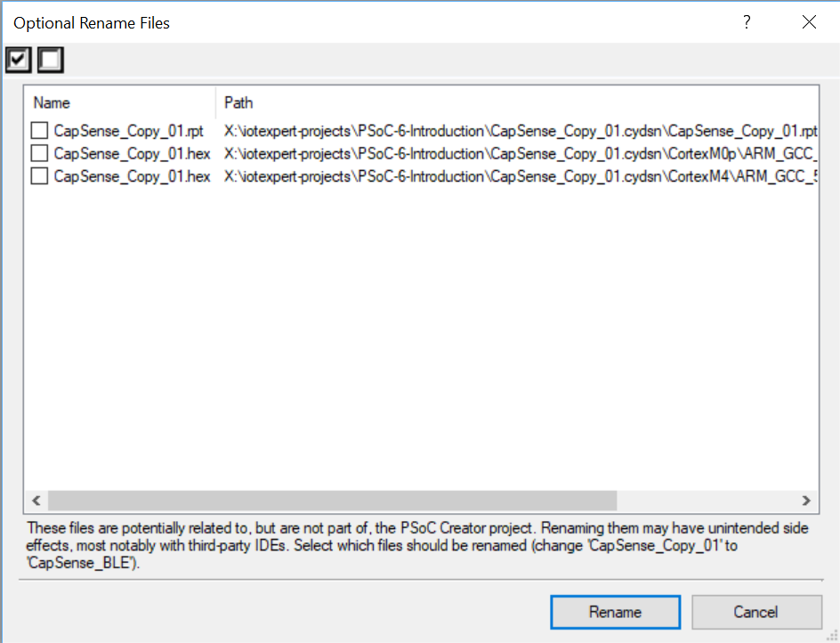
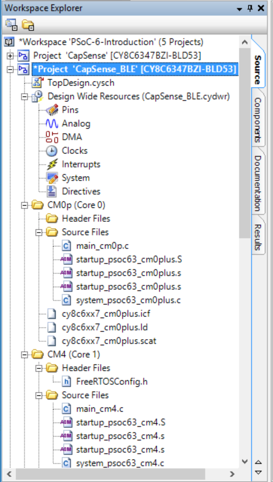
Right click and rename the project to be CapSense_BLE

When is asks you to rename… do it

It should look like this now.

Add and Configure the BLE Component

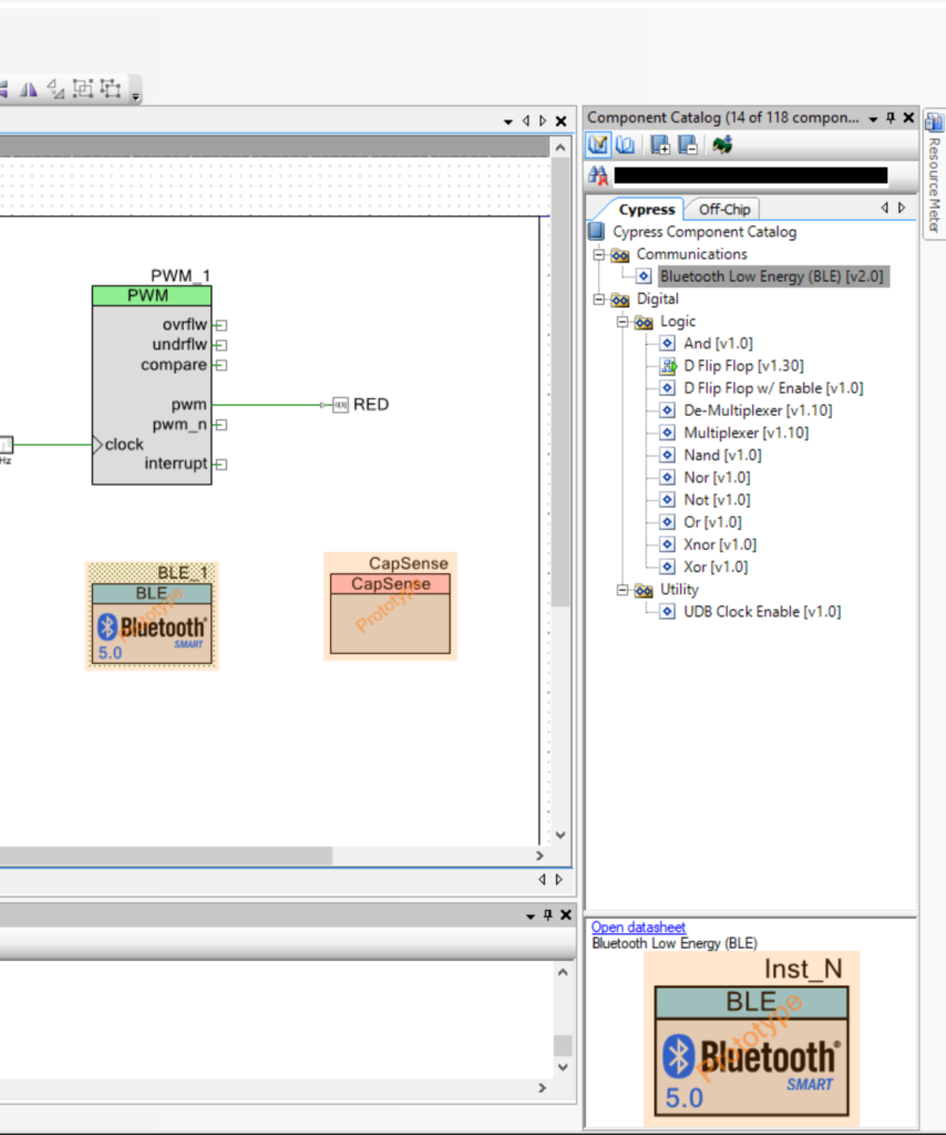
Go to the Component Catalog and find the Bluetooth Low Energy component and drag/drop it into your design schematic.

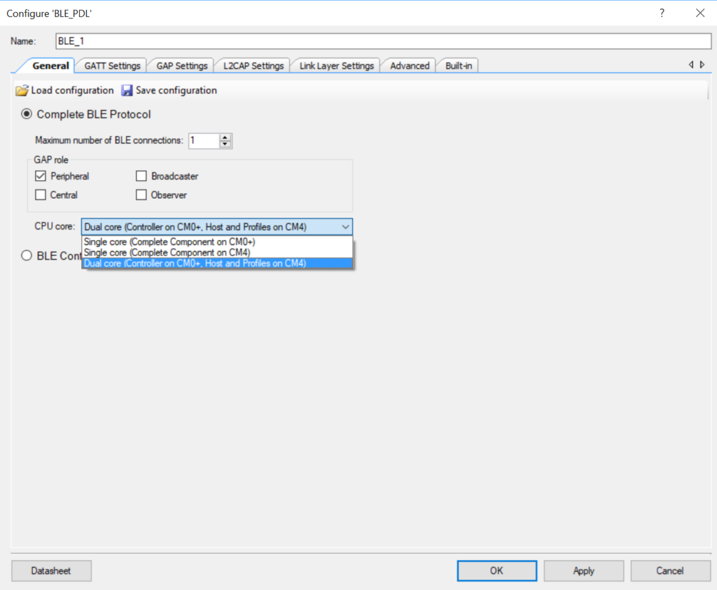
Configure the component to be a “Dual Core …” and set the  number of connections to 1.

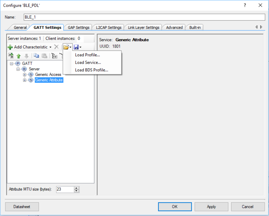
Add the Capsense service to your server by clicking “Load Service…”

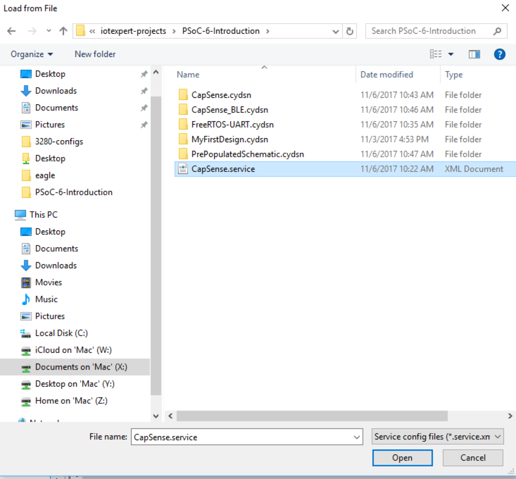
And selecting the “CapSense.service” file.  I created this file to have the right UUIDs and characteristics.

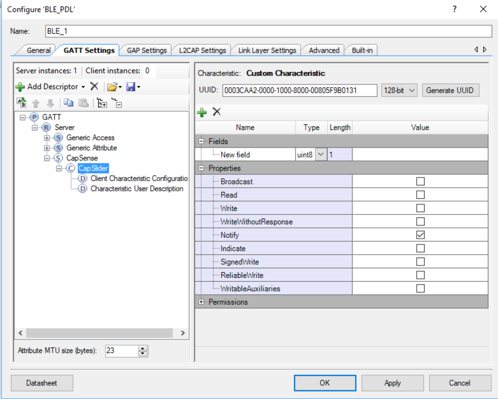
You can now look at the CapSense Slider service and the CapSlider characteristic

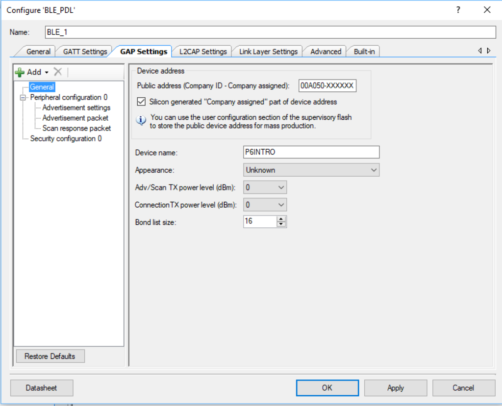
Set the name of our peripheral in the “GAP Settings”.  In this case I will call it P6INTRO.

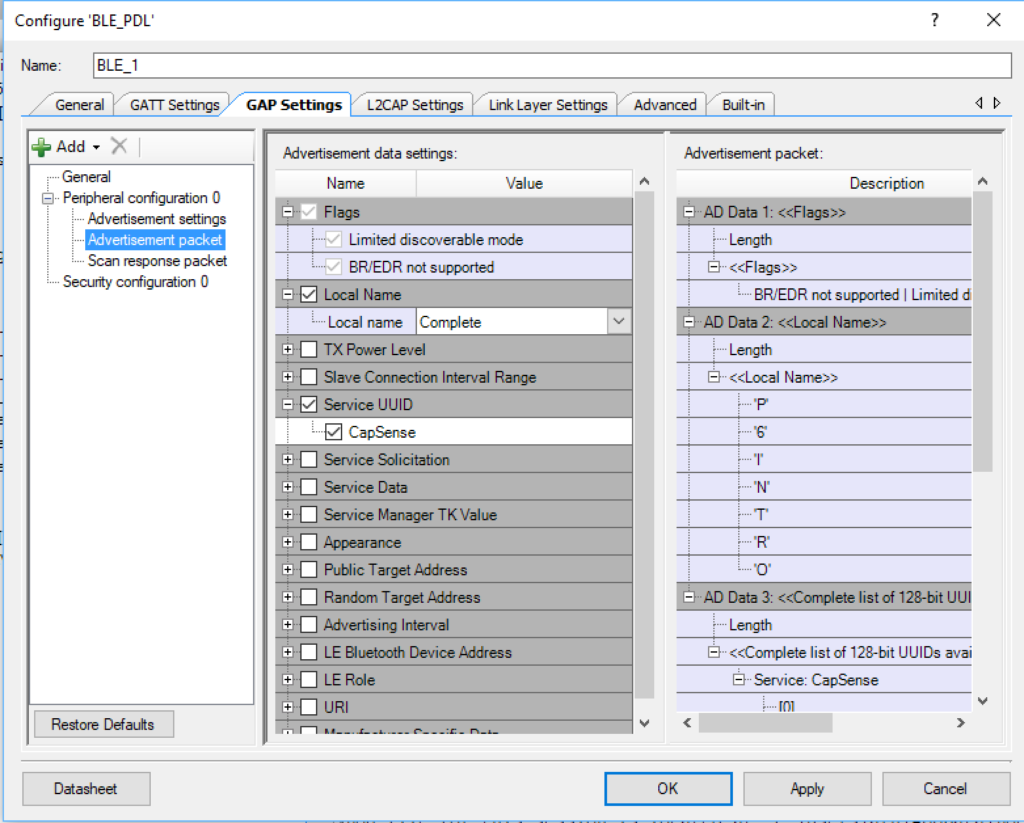
Configure the advertising settings to advertise the name of the device and the CapSense Service.

Fix the Interrupts

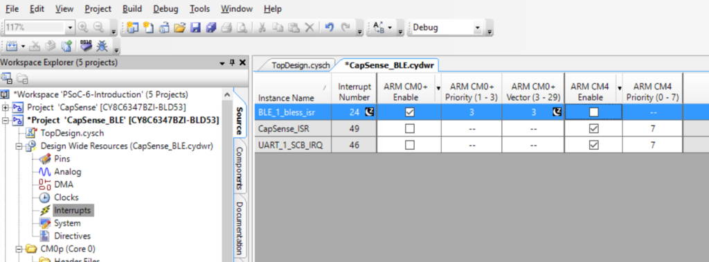
Almost all of the interrupt sources in the PSoC 6 can be connected to one or both of the Cortex cores.  I think that you are probably crazy to attach it to both.  In this case the BLE interrupt needs to be connected to the “ARM CM0+”

Update main_cm0p. c to Run the BLE Radio Controller

#include <project.h>
int main(void)
{
    __enable_irq(); /* Enable global interrupts. */
  
   
    Cy_BLE_Start(0);
    
    /* Enable CM4.  CY_CORTEX_M4_APPL_ADDR must be updated if CM4 memory layout is changed. */
    Cy_SysEnableCM4(CY_CORTEX_M4_APPL_ADDR); 
    

    for(;;)
    {
        Cy_BLE_ProcessEvents();
    }
}

Add three global variables to main_cm4.c

The BLE Task will have a queue that the CapSense will use to send out changes in the CapSense Slider.

QueueHandle_t bleQueueHandle;
int connected=0;
int notify=0;

Create a new task to process the BLE

The. task will just start up the BLE processing on the CM4.  Then it will cause the BLE event manager to run.  If a new value of the CapSense slider is set, it will send out a notification using the “notifyCapSense” function

// bleTask handles the BLE connection (or not).. if the user connects and turns on
// notifications then it sends out new values of the CapSense slider
void bleTask(void *arg)
{
    (void)arg;   
    uint32_t msg;
    
    printf("Starting BLE Task\r\n");
    bleQueueHandle = xQueueCreate(1,sizeof(uint32_t));
    Cy_BLE_Start(customEventHandler);
    
    for(;;)
    {
        Cy_BLE_ProcessEvents();
        
        // CapSense task will put CapSense slider values in the bleQueueHandle
        if(xQueueReceive(bleQueueHandle,&msg,0) == pdTRUE)
            notifyCapSense((uint8_t)msg);
       
        taskYIELD();
    }
}

Create an Event Handler

You will need a task to handle the BLE processing on the CM4.  Each time a Bluetooth event occurs you will need to do “something”

// This event handler is called by BLE
void customEventHandler(uint32_t event, void *eventParameter)
{
     cy_stc_ble_gatts_write_cmd_req_param_t   *writeReqParameter;   

    switch (event)
    {
        case CY_BLE_EVT_STACK_ON:
        case CY_BLE_EVT_GAP_DEVICE_DISCONNECTED: // Central disconnects
            Cy_BLE_GAPP_StartAdvertisement(CY_BLE_ADVERTISING_FAST,CY_BLE_PERIPHERAL_CONFIGURATION_0_INDEX);
            connected = 0;
            notify=0;
        break;

        case CY_BLE_EVT_GATT_CONNECT_IND: // A Central connection is made
            connected = 1;
        break;
        
        case CY_BLE_EVT_GATTS_WRITE_REQ:
            writeReqParameter = (cy_stc_ble_gatts_write_cmd_req_param_t *)eventParameter;

            if(CY_BLE_CAPSENSE_CAPSLIDER_CLIENT_CHARACTERISTIC_CONFIGURATION_DESC_HANDLE ==  writeReqParameter->handleValPair.attrHandle)
                notify = writeReqParameter->handleValPair.value.val[0];
              
            Cy_BLE_GATTS_WriteRsp(writeReqParameter->connHandle);
        break;

        default: // Ignore all other events
        break;
    }
}

Make a Function to Send Notifications

// This function is run inside BLE Task and sends notification if you are connected and notifications are on
void notifyCapSense(uint8_t capValue)
{    
    if(!(connected && notify))
        return;
    
    cy_stc_ble_gatts_handle_value_ntf_t v1;
    v1.connHandle = cy_ble_connHandle[0];
    v1.handleValPair.attrHandle = CY_BLE_CAPSENSE_CAPSLIDER_CHAR_HANDLE;
    v1.handleValPair.value.len = 1;
    v1.handleValPair.value.val = &capValue;
    
    Cy_BLE_GATTS_Notification(&v1);
        
}

EDIT!!!!

If you look at the source code at GitHub you will find that I removed the variables “connected” and “notify” and I changed the notifyCapSense function.  This was done because the BLE PDL implementation was greatly improved and simplified. The new function iterates through the connections and sends the notification to all of them.  This was done to handle multiple connections.

// This function is run inside BLE Task and sends notification if you are connected and notifications are on
void notifyCapSense(uint8_t capValue)
{    
   
    unsigned int index;
    
    printf("Sending CapSense %d\r\n",capValue);
   
    cy_stc_ble_gatt_handle_value_pair_t handleValuePair;
    handleValuePair.attrHandle = CY_BLE_CAPSENSE_CAPSLIDER_CHAR_HANDLE;
    handleValuePair.value.val = &capValue;
    handleValuePair.value.len = 1;
    
    Cy_BLE_GATTS_WriteAttributeValueLocal(&handleValuePair);
   
    /* Iterate and send notiication to all the connected devices that are ready to receive notification */
    for(index = 0; index <CY_BLE_CONN_COUNT; index++)
    {     
        Cy_BLE_GATTS_SendNotification(&cy_ble_connHandle[index], &handleValuePair);
    }
        
}

Update the capSenseTask to Send Values

Inside of the capsenseTask you need to send new values of the slider to the BLE task via the Queue.  Meaning the BLE task needs to send out notifications, but it can only do that if the capsenseTask notifies it of changes.

sliderPos=CapSense_GetCentroidPos(CapSense_LINEARSLIDER0_WDGT_ID);
            if(sliderPos<0xFFFF) // If they are touching the slider then send the %
            {
                msg = sliderPos;
                xQueueSend(pwmQueueHandle,&msg,0); // Send message to PWM - change brightness
                xQueueSend(bleQueueHandle,&msg,0); // Send message to BLE
            }

Add the bleTask to main function in main_cm4.c

In the main function you need to start the BLE Task.

xTaskCreate( bleTask, "BLE Task",4096,0,3,0);

Program and Test

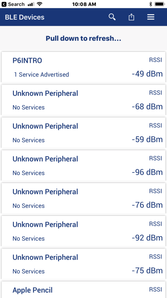
To test this project I will run the CySmart iOS App.  First, you can see all of the devices that are advertising

CySmart

Scroll left (or right) to find the “CapSense Slider”

When you see it, Press on the CapSense Slider Icon

Then put your finger on the slider and you should see it change

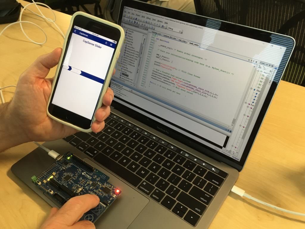
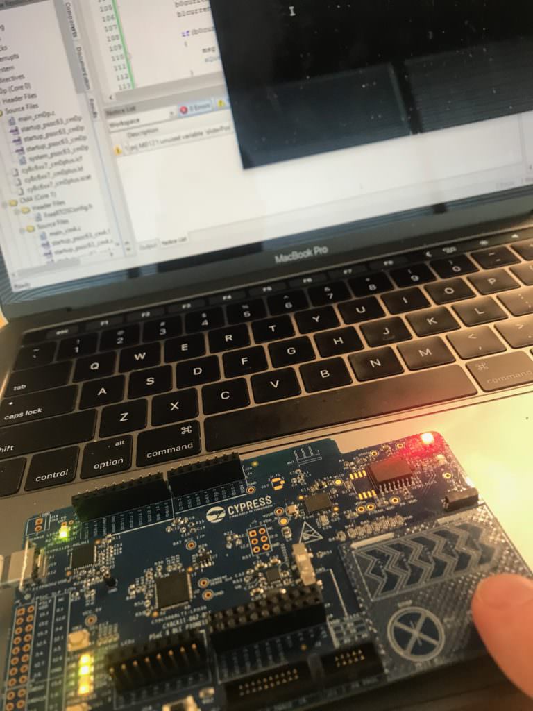
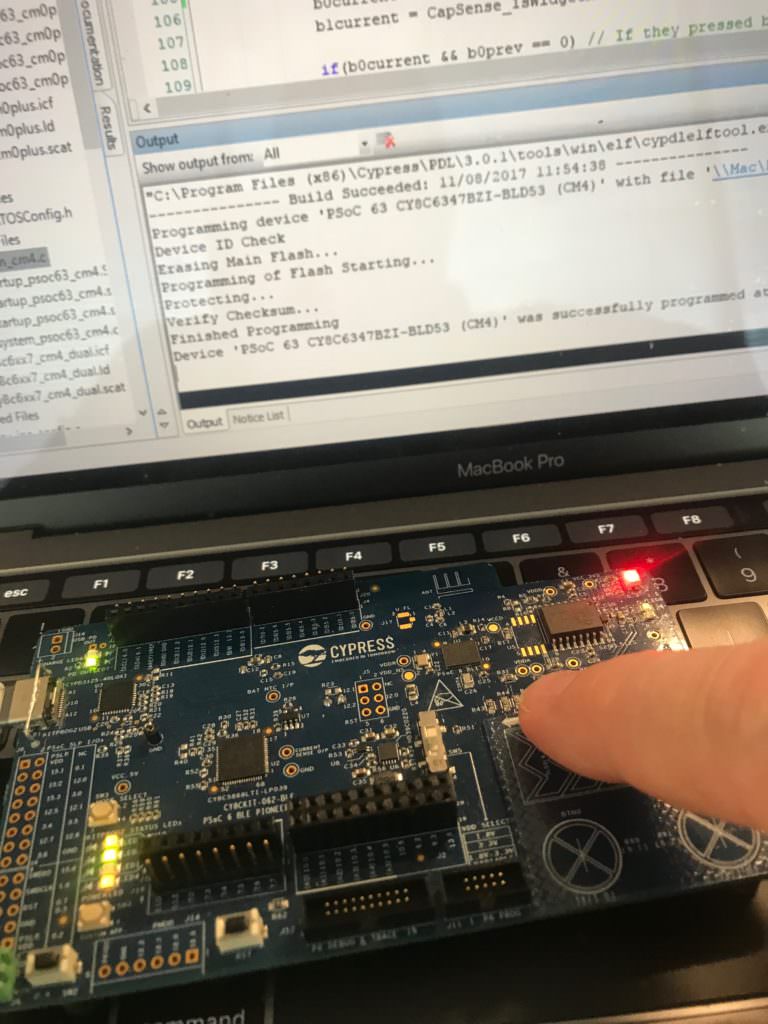
Here is a picture of the whole system.

PSoC 6 BLE CapSense & CySmart

Lesson 4 – PSoC 6 Introduction: CapSense

PSoC 6 Introduction

# Title Comment
0 A Two Hour PSoC 6 Class An introduction to the PSoC 6 class with links to all of the documents
1 Resources Links to all of the Cypress PSoC 6 information including videos, application notes etc.
2 Your First Project Learn how to build a PSoC 6 project and program your CY8CKIT-062-BLE development kit
3 FreeRTOS and a Debugging UART Build a project using FreeRTOS including a debug console with the UART
4 CapSense Build a project using the Mutual Cap Buttons and Self Cap Slider
5 Bluetooth Low Energy Build a CapSense project using BLE and CySmart

Since I did the webinar several things have happened

  1. Lesson 4: I fixed an error in the stack size for FreeRTOS
  2. Lesson 5: The PSoC Creator BLE PDL has been upgraded to greatly simplify the notifyCapSense function

All of the projects are available at git@github.com:iotexpert/psoc-6-introduction.git or www.github.com/iotexpert/psoc-6-introduction

Project Description

This project is a demonstration of a PSoC 6 running an RTOS using CapSense and the UART to control the intensity of the Red LED with a Pulse Width Modulator (PWM)

The CapSense will:

  • BTN0 will set the intensity to 0%
  • BTN1 will set the intensity to 100%
  • CapSense slider will set the intensity (0-100) when touched

The UART will:

  • UART Key ‘0’ turn the LED to intensity = 0%
  • UART Key ‘1’ turn the LED to intensity = 100%
  • UART Key ‘5’ turn the LED to intensity = 50%
  • UART Key ‘?’ will printout help

How does it work?

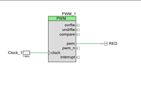
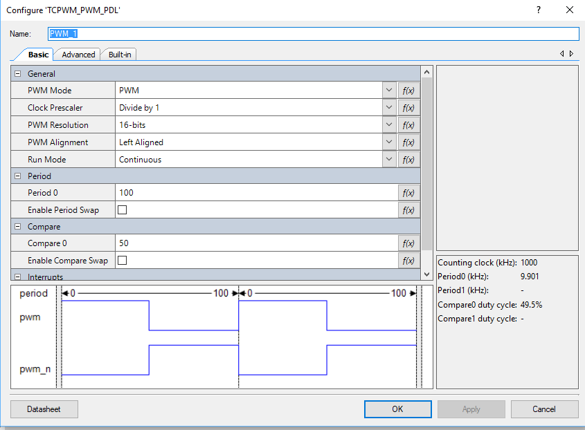
You can control the intensity of an LED with a pulse width modulator and a high frequency input clock.  If the duty cycle is “small” then the intensity of the LED is low (meaning dim).  If the duty cycle is “big” then the intensity is “high”.  A 0% duty cycle will be off, a 50% duty cycle will be in the middle and 100% duty cycle will be all on.  To make this work I will set the input clock to 1 MHz and the PWM Period to 100.  The PWM Compare value will then be set between 0 and 100 to represent brightness in percent.

The Cypress CapSense block has two sensing modes, mutual capacitance and self capacitance.   The CY8CKIT-062-BLE has two Mutual Capacitance buttons and a 5 segment Self or Mutual Capacitance Slider.

The project will have three tasks

  • UART – Read data from the keyboard and send messages to the PWM Task
  • CapSense – Read finger positions from the slider and buttons and send messages to the PWM Task
  • PWM – Will have an input queue, when a integer message is received it will set the PWM compare value to the integer received (0 >= msg <= 100)

How am I going to do it?

  1. Create a new project by copy/paste the FreeRTOS-UART Project
  2. Configure Schematic for Higher Frequency Clock and Change PWM Settings
  3. Add a new PWM task and modify the UART
  4. Program and Test
  5. Edit the FreeRTOS.h and make a bigger heap
  6. Add the CapSense Buttons to the Schematic and Set the Pins
  7. Add the capsenseTask
  8. Program and Test
  9. Add the CapSense Slider to the Schematic and Set the Pins
  10. Update the capsenseTask
  11. Program and Test

Create a new Project by Copy/Paste of FreeRTOS-UART Project

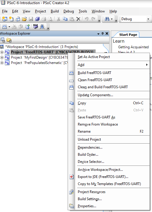
Right click on the FreeRTOS-UART Project then select “Copy”

PSoC 6 Create New Project - Copy

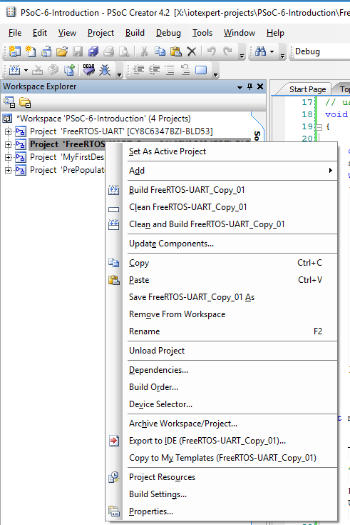
Then right click on the Workspace and select “Paste”

PSoC 6 Create New Project - Paste


Right click on “FreeRTOS-UART-Copy01)” and rename it to “CapSense”

PSoC 6 Create New Project - Rename

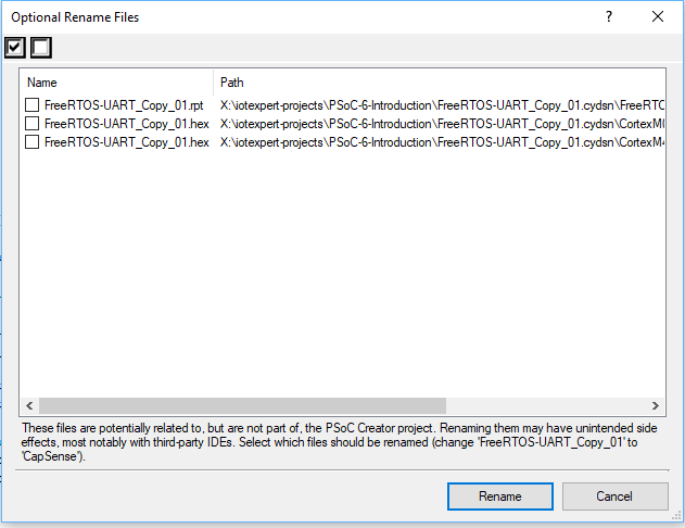
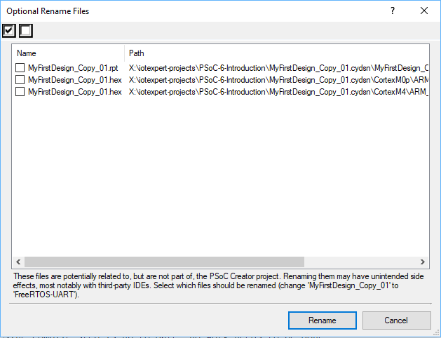
Click “Rename” (all of these files will be regenerated so it doesn’t really matter)

PSoC 6 Create New Project - Rename

Close all windows by right clicking “Close All But This” on the start tab

PSoC Creator Close All Windows

Configure Schematic for Higher Frequency Clock and Change PWM Settings

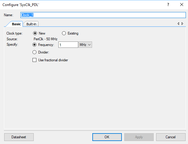
If you blink the LED fast enough, you will not be able to see the “Blink” it will just appear to be bright or dim based on the duty cycle.  Start by changing the clock to 1 MHz.

PSoC 6 Update Clock

Double click on the PWM_1

PSoC 6 Update TCPWM

Fix the Period to be 100 and the compare to be 50

PSoC 6 Update TCPWM

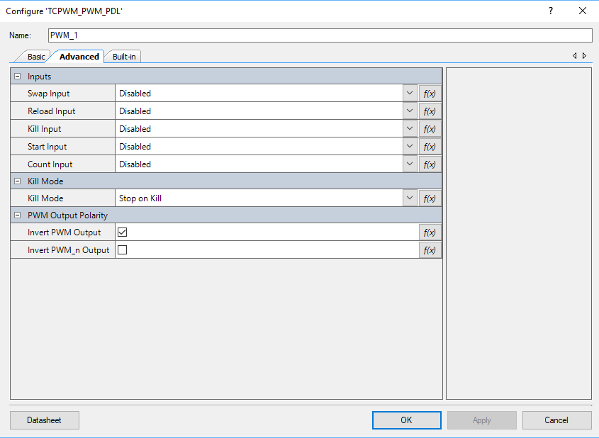
The LED on the CY8CKIT-062-BLE is active low which means that when it is 0 the LED is on.  I want the opposite behavior so I can configure the PWM output to be inverted on the advanced tab.  Click the button next to “Invert PWM Output”

PSoC 6 Update TCPWM Advanced

Add a new PWM Task and Modify the UART Task

Next, I will create the pwmTask function.  It will simply wait for someone to send a message to the pwmQueue.  The message is simply a uint32_t that represents the PWM compare value … aka the percent intensity of the LED.  When it gets the value, it will update the hardware.

Edit: In the comments below you can see that Charles asked that I clarify where these functions should go.  When I did this, I put them basically at the top of the file… just under the #includes.   The only thing that really matters is that they need to be put before they are used so that the compiler knows the function prototypes.  If you put them after they are used then you need to make forward declarations.

#include "queue.h"
QueueHandle_t pwmQueueHandle; 

// This task controls the PWM
void pwmTask(void *arg)
{
    (void)arg;
    
    uint32_t msg;
    
    printf("Starting PWM Task\r\n");
    pwmQueueHandle = xQueueCreate(1,sizeof(uint32_t));
   
    while(1)
    {
        xQueueReceive(pwmQueueHandle,&msg,portMAX_DELAY);
        Cy_TCPWM_PWM_SetCompare0(PWM_1_HW,PWM_1_CNT_NUM,msg);
   }
}

In the main function you need to start the pwmTask

xTaskCreate(pwmTask,"PWM Task",configMINIMAL_STACK_SIZE*8,0,3,0);

Next, I will update the uartTask

  • To not getchar’s unless there is something in the RX buffer of the UART (line 13).
  • Create a message aka a uin32_t based on the key pressed and send it with xQueueSend
  • If there was nothing there then taskYIELD to one of the other tasks (line 35)
// uartTask - the function which handles input from the UART
void uartTask(void *arg)
{
    (void)arg;
    
    char c;
    uint32_t msg;

    printf("Started UART Task\r\n");
    setvbuf(stdin,0,_IONBF,0);
	while(1)
	{
		if(Cy_SCB_UART_GetNumInRxFifo(UART_1_HW))
		{
		    c = getchar();
    		switch(c)
	    	{
		    	case '0': // send the stop message
			    	msg = 0;
		    		xQueueSend(pwmQueueHandle,&msg,portMAX_DELAY);               
		    	break;
		    	case '1': // Send the start message
		    		msg = 100;
		    		xQueueSend(pwmQueueHandle,&msg,portMAX_DELAY);
		    	break;
			    case '5':
				    msg = 50;
				    xQueueSend(pwmQueueHandle,&msg,portMAX_DELAY);
			    break;
			    case '?': // Print Help 
				    printf("s - stop PWM\r\nS - start PWM\r\n");
			    break;
		    }
		}
		taskYIELD();
    }
}

Program and Test

PSoC 6 Test PWM

Edit the FreeRTOS.h and make a bigger heap

The CapSense task is going to take more heap space that is currently allocated for FreeRTOS.  To fix this I need to edit the FreeRTOS.h and change the heap size to 48K (which I picked out of the air)

#define configTOTAL_HEAP_SIZE                   (48*1024)

Add the CapSense Buttons to the Schematic and Set the Pins

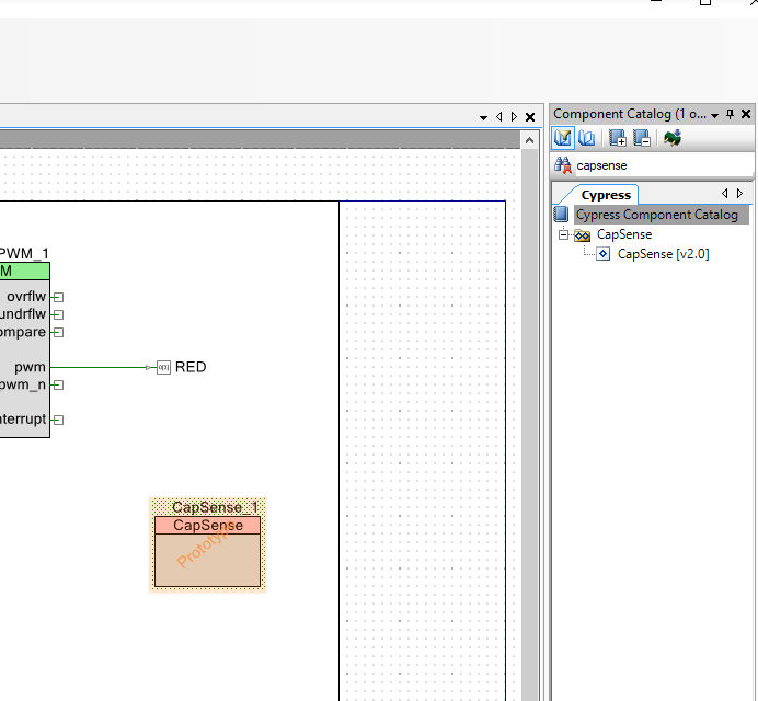
In order to add CapSense to the design, you find the CapSense component in the Component Catalog. Then you drag it into your schematic.

PSoC 6 Add CapSense Component

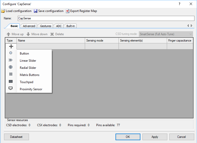
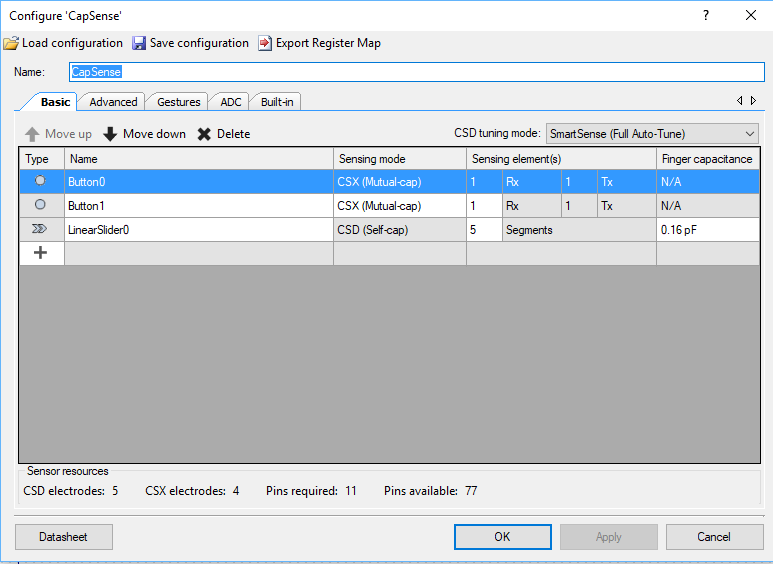
The next thing to do is configure the CapSense block.  I start by re-naming it to “CapSense”.  Then I click on the plus and add two “Button”s to the design.

PSoC 6 Add CapSense Buttons

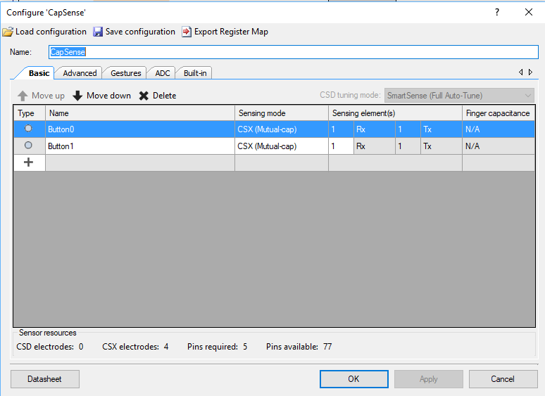
Then I change the configuration to “CSX (Mutual-cap).

PSoC 6 Setup Mutual CapSense

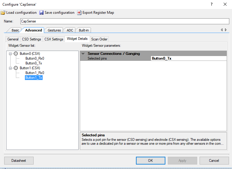
On the CY8CKIT-062-BLE, there is a shared transmit line. This saves 1 pin.  You need to tell the CapSense component that you are using a shared Tx.  To do this click on Advanced -> Widget Details.  Then pick “Button1_tx” and set the Sensor Connection / Ganging to “Button0_Tx”

PSoC 6 Setup CapSense Tx

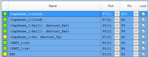
Once the CapSense is configured you need to Set the Pins.

PSoC 6 Fix Pins

Next you run “Generate Application” which will let PSoC Creator place and route the design plus bring in all of the required drivers.

Add the capsenseTask

Now create a new task function called capsenseTask it will

  • Use 4 variables to hold the previous and current state of the buttons (line 81-84)
  • Start the CapSense Block (line 88)
  • Start CapSense Scanning (line 89)
  • If the CapSense hardware is not busy then you can talk to it. (line 93)
  • Start by turning the raw data into useable information (line 96)
  • Read the state of the buttons (line 98-99)
  • If the button state has changed, then send a message to the PWM Task (line 101-110)
  • Save the state of the buttons (line 111-112)
  • Update the baseline information (line 114)
  • Start Scanning again (line 115)
  • If the CapSense block is busy then yield to the other tasks (line 118)
// capsenseTask
// Read buttons and slider using CapSense and send messages to pwmQueue
void capsenseTask(void *arg)
{
    (void)arg;
    
    uint32_t msg;
    
    int b0prev=0;
    int b1prev=0;
    int b0current=0;
    int b1current=0;
    int sliderPos;
    
    printf("Starting CapSense Task\r\n");
    
    CapSense_Start();
    CapSense_ScanAllWidgets();
        
    for(;;)
    {
        if(!CapSense_IsBusy())
        {
            CapSense_ProcessAllWidgets();
/*
            sliderPos=CapSense_GetCentroidPos(CapSense_LINEARSLIDER0_WDGT_ID);
            if(sliderPos<0xFFFF) // If they are touching the slider then send the %
            {
                msg = sliderPos;
                xQueueSend(pwmQueueHandle,&msg,portMAX_DELAY);
            }
*/
            b0current = CapSense_IsWidgetActive(CapSense_BUTTON0_WDGT_ID);
            b1current = CapSense_IsWidgetActive(CapSense_BUTTON1_WDGT_ID); 
            
            if(b0current && b0prev == 0) // If they pressed btn0
            {
                msg = 0; 
                xQueueSend(pwmQueueHandle,&msg,portMAX_DELAY);
            }
            if( b1current && b1prev == 0) // If they pressed btn0
            {
               msg = 100;
               xQueueSend(pwmQueueHandle,&msg,portMAX_DELAY);  
            }
            b0prev = b0current;
            b1prev = b1current;
               
            CapSense_UpdateAllBaselines();
            CapSense_ScanAllWidgets();
        }
        else
            taskYIELD();
            
    }    
}

And start the capSense task in main.

xTaskCreate( capsenseTask, "CapSense Task",2048*2,0,3,0);

Program and Test

PSoC 6 Test CapSense Buttons

Add the CapSense Slider to the Schematic and Set the Pins

To make the slider work you need to add a LinearSlider widget by pressing the “+” and selecting LinearSlider

PSoC 6 Add CapSense Slider

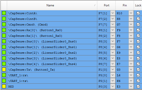
Once you have added the LinearSlider you need to set the pins for the new CapSense Slider

PSoC 6 Fix CapSense Slider Pins

Update the capsenseTask to Include the Slider

The changes are small to make the LinearSlider work.  You just need to

  1. Read the position of the slider (line 99)
  2. The slider will be 0xFFFF if there is no touch… in which case ignore it (line 100)
  3. If you got a touch, then make that a message and set it to the PWM (line 102-103)
          sliderPos=CapSense_GetCentroidPos(CapSense_LINEARSLIDER0_WDGT_ID);
            if(sliderPos<0xFFFF) // If they are touching the slider then send the %
            {
                msg = sliderPos;
                xQueueSend(pwmQueueHandle,&msg,portMAX_DELAY);
            }

Program and Test

PSoC 6 CapSense Slider

Lesson 3 – PSoC 6 Introduction: FreeRTOS and a Debugging UART

PSoC 6 Introduction

# Title Comment
0 A Two Hour PSoC 6 Class An introduction to the PSoC 6 class with links to all of the documents
1 Resources Links to all of the Cypress PSoC 6 information including videos, application notes etc.
2 Your First Project Learn how to build a PSoC 6 project and program your CY8CKIT-062-BLE development kit
3 FreeRTOS and a Debugging UART Build a project using FreeRTOS including a debug console with the UART
4 CapSense Build a project using the Mutual Cap Buttons and Self Cap Slider
5 Bluetooth Low Energy Build a CapSense project using BLE and CySmart

Since I did the webinar several things have happened

  1. Lesson 4: I fixed an error in the stack size for FreeRTOS
  2. Lesson 5: The PSoC Creator BLE PDL has been upgraded to greatly simplify the notifyCapSense function

All of the projects are available at git@github.com:iotexpert/psoc-6-introduction.git or www.github.com/iotexpert/psoc-6-introduction

Project Description

This project will show you how to build a PSoC 6 project that is running FreeRTOS and printing information to the debugging UART

How does it work?

The PSoC 6 is a very capable, fast dual Coretex-M MCU.  In order to manage your design complexity that can be attacked with this chip, we gave you the ability to use a Real Time Operating System – FreeRTOS.  With a few simple clicks it will startup for you.

The CY8CKIT-062-BLE has a KitProg-2 Debugger/Programmer on board.  In addition to Program/Debug it can also serve as a USB <–> UART bridge which will allow you to open a terminal program on your PC to do Input/Output with a UART in the PSoC 6.

How am I going to do it?

  1. Copy “MyFirstDesign” to Start a New Project
  2. Modify the Build Settings to add Debug Printing and FreeRTOS
  3. Add the UART to the Schematic and Assign the Pins
  4. Create the UART Test Firmware
  5. Program and Test the Debug UART
  6. Modify firmware for FreeRTOS
  7. Program and Test
  8. A Tour of PDL for the TCPWM

Copy “MyFirstDesign” to Start a New Project

Right click on “MyFirstDesign” and select “Copy”

PSoC Creator Copy Project

Then right click on the workspace and select “Paste”

PSoC Creator Copy/Paste

Then right click on “MyFirstDesign_Copy_01” and select rename.  Then type in a reasonable name like “FreeRTOS-UART”

PSoC Creator Copy / Paste

PSoC Creator will ask you about some files.  Just click “Rename”

PSoC Creator Rename

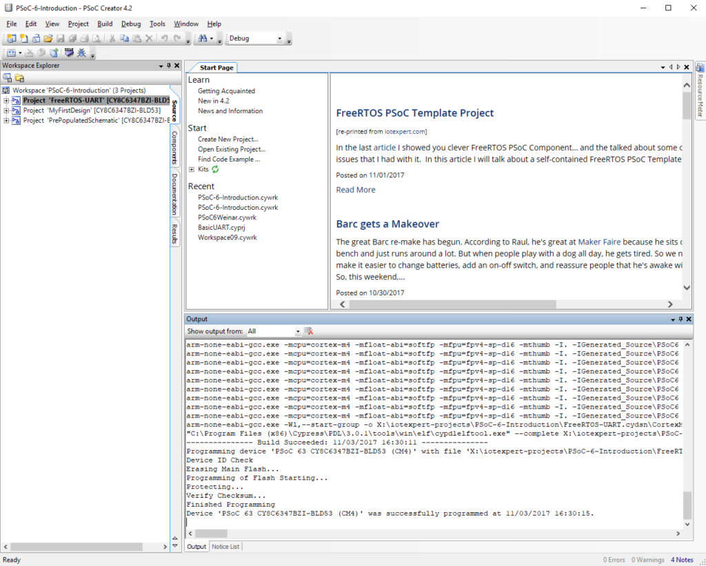
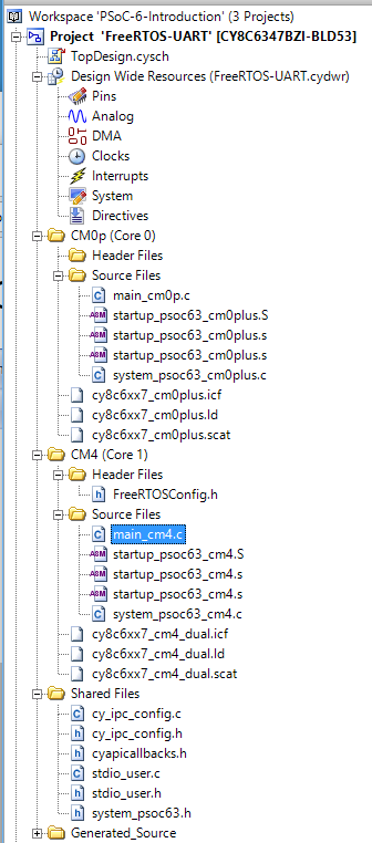
Now you will have three projects in your workspace.  I typically click “Program” which will build the copied project and program the development kit… just to make sure that stuff still works.

PSoC Creator Workspace

Modify the build settings to add debug printing and FreeRTOS

You can build massively complex systems with PSoC 6.  In order to help manage that complexity I like to turn on debug printing so that “printf” works.  I also like to use a Real Time Operating System (FreeRTOS).  PSoC Creator has both of these things built in.  We called the printf functionality “Retarget I/O” because you need to “target” the Input / Output of the printf … aka STDIN and STDOUT to a peripheral in the PSoC.  The best peripheral to use for printf is the UART that is attached to your computer via kitprog2.

To add printf and FreeRTOS to your project you need to: Right click on the project and select “Build Settings…”

PSoC Creator Modify Build Settings

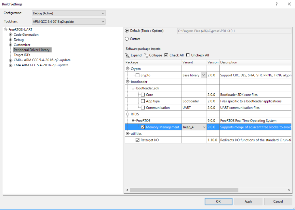
Click on the Peripheral Driver Library and then select “FreeRTOS” and “Memory Management heap_4”.  Then select “Retarget I/O”.  When you build your project this will cause PSoC Creator to add both of these to your project.

PSoC Creator Build Settings FreeRTOS

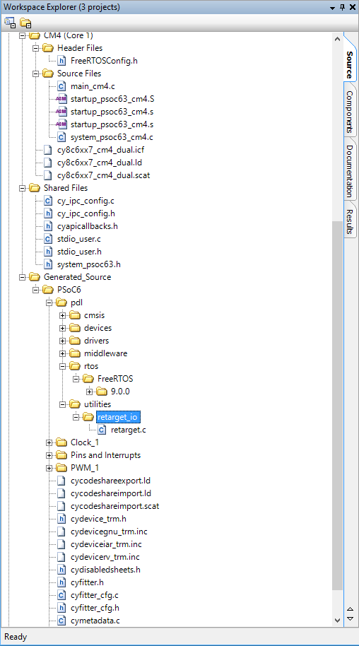
Select Build->Generate Application and notice that PSoC Creator added a number of files to your project including the FreeRTOS, stdio_user.c/.h and retarget_io

PSoC Creator retarget_io.c

Add the UART to the Schematic and Assign the Pins

In order to printf, getchar and putchar  you need to attach c standard library stdin and stdout to “something”.  The best “something” is the UART that is attached to the KitProg2 which is attached to your computer.  Then you can open a terminal program (like Putty) and read and write to the PSoC.

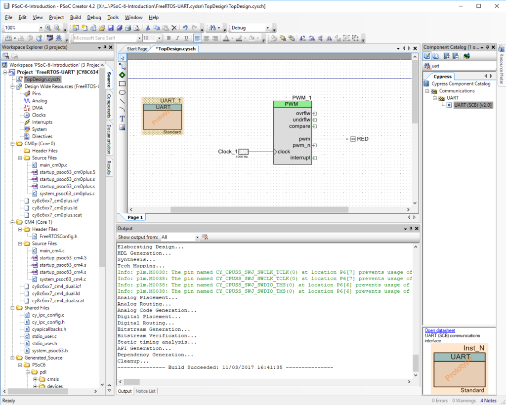
So, to do this you need to add a UART to your design schematic from the component catalog.  In the picture below I just typed “uart” in the search box.

PSoC Creator Debug UART

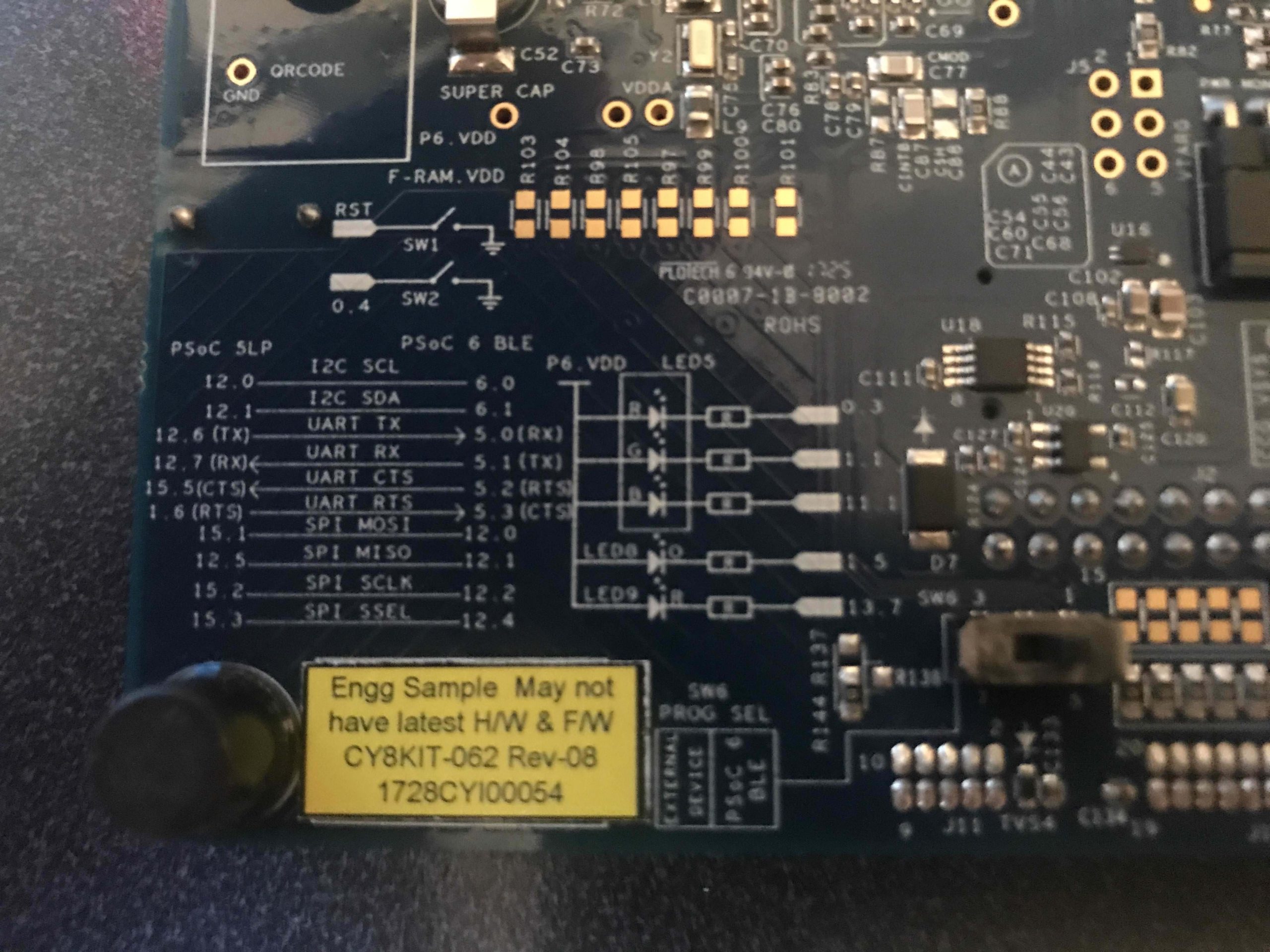
What pins on the PSoC 6 BLE is the UART attached to?  Well… if you turn over your CY8CKIT-062-BLE you will find a little map that show that the PSoC 6 BLE UART is attached to the PSoC 5LP UART.  The PSoC 5LP is programmed with the KitProg2 firmware.

PSoC 6 CY8CKIT-062-BLE

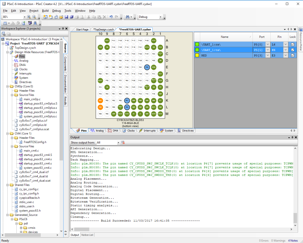
To attach those pins in your firmware you just double click on the “Pins” tab in the DWR.  Then you can select “Port” for the UART RX and TX.  Look at the picture below.

PSoC 6 PSoC Creator Pin Settings

Now that I have all of that done, I run “Build->Generate Application” to get all of the new settings into my project.

Create the UART Test Firmware

The next step in making the printf work is to “retarget” it to the UART we just put in the schematic.  Open “stdio_user.h” and add “include <project.h>” (line 130) and change IO_STDOUT_UART and IO_STDIN_UART to be UART_1_HW.  The name “UART_1” on lines 136-137

#include <project.h>
#include "cy_device_headers.h"

/* Must remain uncommented to use this utility */
#define IO_STDOUT_ENABLE
#define IO_STDIN_ENABLE
#define IO_STDOUT_UART      UART_1_HW
#define IO_STDIN_UART       UART_1_HW

Now edit your main_cm4.c to:

  • Turn on the UART with UART_1_Start() on line
  • Then a couple of printfs lines 24-25

Note that “\033[2J\033[H” is just a VT100 escape sequence for clear screen and go home.

#include "project.h"
#include <stdio.h>

int main(void)
{
    __enable_irq(); /* Enable global interrupts. */

    /* Place your initialization/startup code here (e.g. MyInst_Start()) */

    PWM_1_Start();
    UART_1_Start();
    
    printf("3[2J3[H"); // Clear Screen
    printf("Test\r\n");
    
    
    for(;;)
    {
        /* Place your application code here. */
    }
}

Program and Test the Debug UART

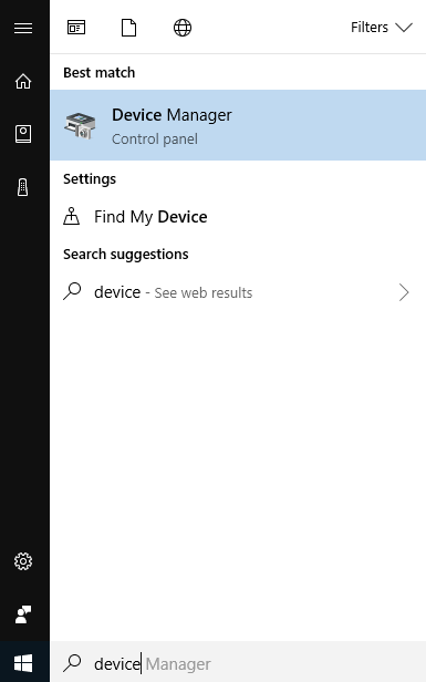
You need to figure out which com port that the KitProg2 is attached to.  To do this run the device manager by pressing the “windows” button then typing “device manger”

Device Manager

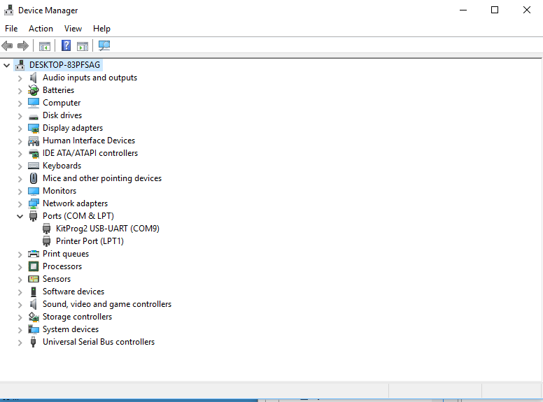
Click on ports.  Then you can see that the programmer is “KitProg2” and that the UART is attached to COM9 (everyone will have a different number)

Device Manager

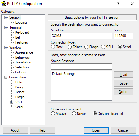
Run Putty (or  your favorite terminal program)

Putty

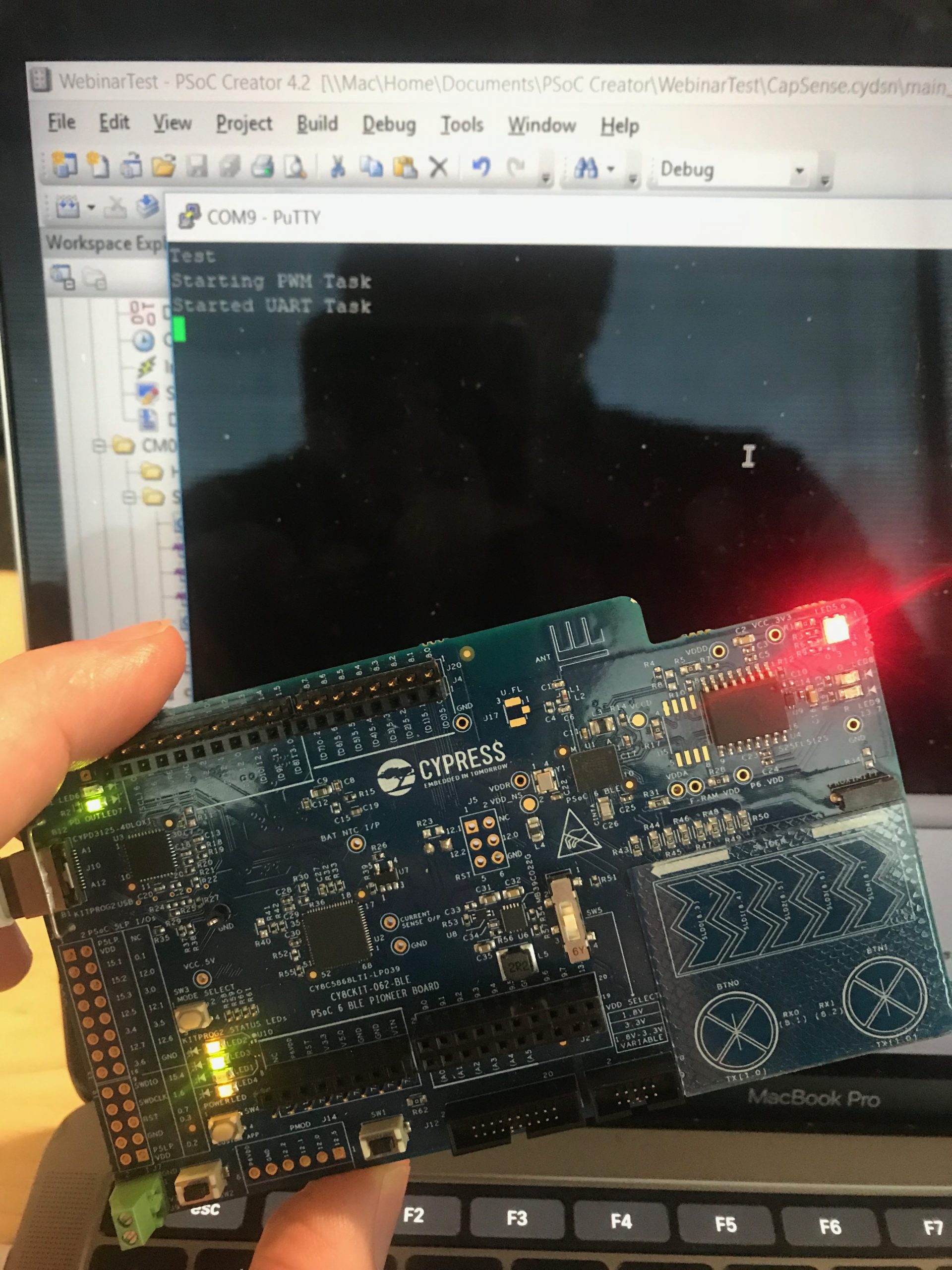
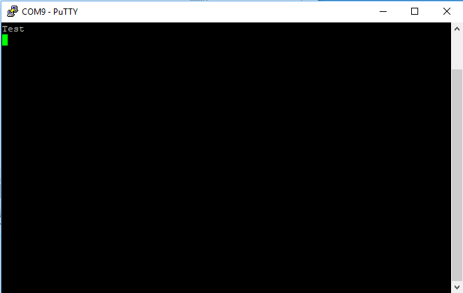
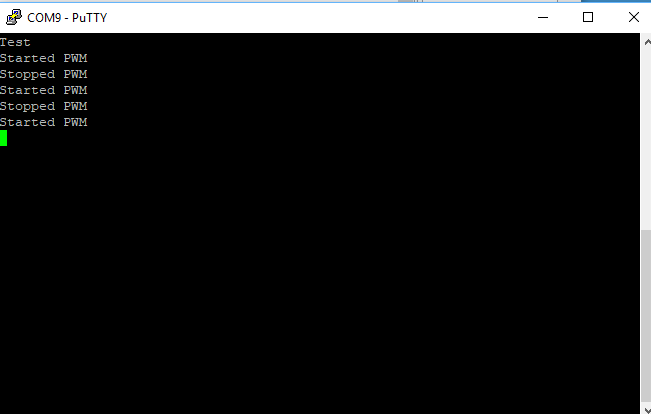
Press the program button on PSoC Creator and you should see your test print

Putty PSoC 6 UART

Modify firmware for FreeRTOS

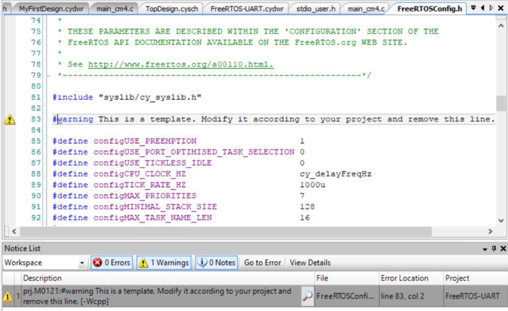
When I look out the output window from the previous step you can see that there is a warning message from FreeRTOS.  Lets fix that warning (by deleting line 83).  While we are at it, lets change the heap size to 48K (48*1024)

Now lets turn on FreeRTOS. Double click on main_cm4.c to open it in the code editor.

Modify FreeRTOS Firmware

Add the following firmware to your project.

The uartTask is function that FreeRTOS uses to create a Task.  This task will control the uart. (which is amazingly enough why I named it uartTask)

  • The function call “setvbuff” turns of buffering on stdin… which means every character will immediately come through to your program
  • getchar just gets a character from the terminal
  • the ‘s’ and ‘S’ will start and stop the PWM (more to follow)

In main I

  • Create a task for the uartTask (line 56)
  • Start FreeRTOS (line 57)
/* ========================================
 *
 * Copyright YOUR COMPANY, THE YEAR
 * All Rights Reserved
 * UNPUBLISHED, LICENSED SOFTWARE.
 *
 * CONFIDENTIAL AND PROPRIETARY INFORMATION
 * WHICH IS THE PROPERTY OF your company.
 *
 * ========================================
*/
#include "project.h"
#include <stdio.h>
#include "FreeRTOS.h"
#include "task.h"

// uartTask - the function which handles input from the UART
void uartTask(void *arg)
{
    (void)arg;
    char c;
    setvbuf(stdin,0,_IONBF,0);
    while(1)
    {
        c = getchar();
        switch(c)
        {
            case 's': // Stop the PWM
                printf("Stopped PWM\r\n");
                Cy_TCPWM_PWM_Disable(PWM_1_HW,PWM_1_CNT_NUM);
                
            break;
            case 'S': // Start the PWM
                printf("Started PWM\r\n");
                Cy_TCPWM_PWM_Enable(PWM_1_HW,PWM_1_CNT_NUM);
                Cy_TCPWM_TriggerStart(PWM_1_HW, PWM_1_CNT_MASK);
            break;
        }
    }
}


int main(void)
{
    __enable_irq(); /* Enable global interrupts. */

    /* Place your initialization/startup code here (e.g. MyInst_Start()) */

    PWM_1_Start();
    UART_1_Start();
    
    printf("3[2J3[H"); // VT100 Clear Screen
    printf("Test\r\n");
 
    // Mask a FreeRTOS Task called uartTask
    xTaskCreate(uartTask,"UART Task",configMINIMAL_STACK_SIZE,0,3,0);
    vTaskStartScheduler();  // Will never return
    
    for(;;) // It will never get here
    {
    }
}

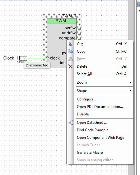
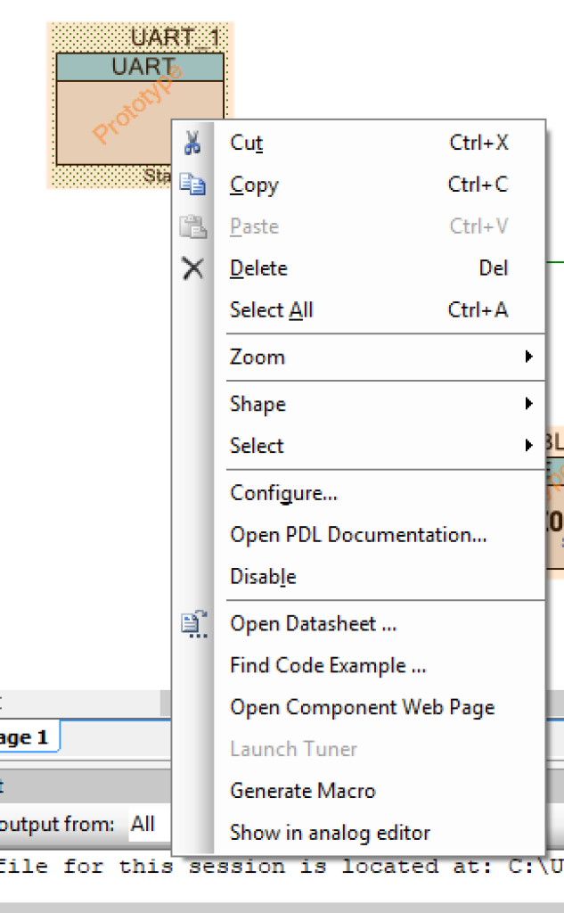
How did I figure out how to start/stop the PWM?  To find the documentation for “PDL” aka the Peripheral Driver Library, you can right click on the component in the schematic and select “Open PDL Documentation”

PSoC 6 TCPWM

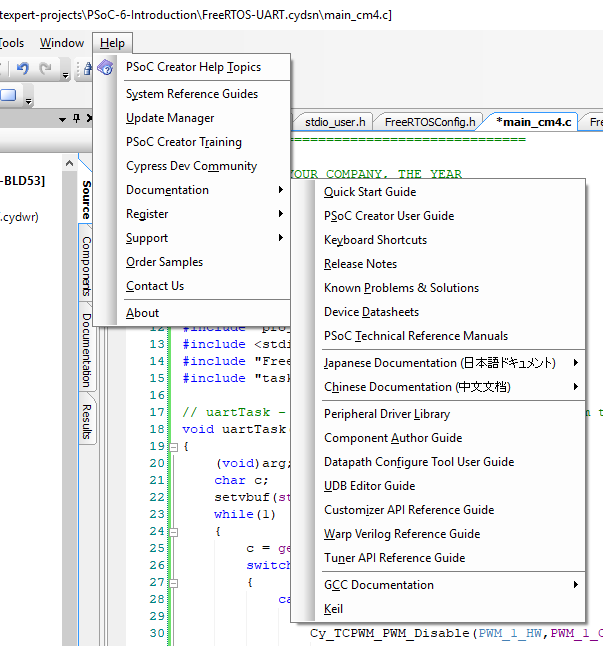
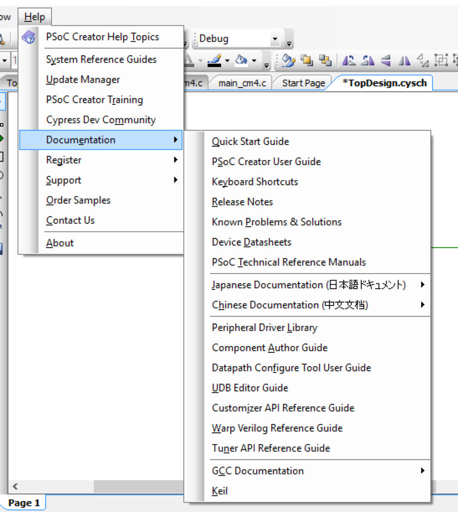
Or you can open “Help –> Documentation –> Peripheral Driver Library”

PSoC Creator Help

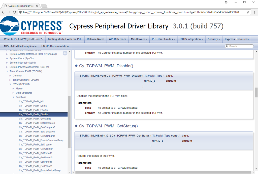
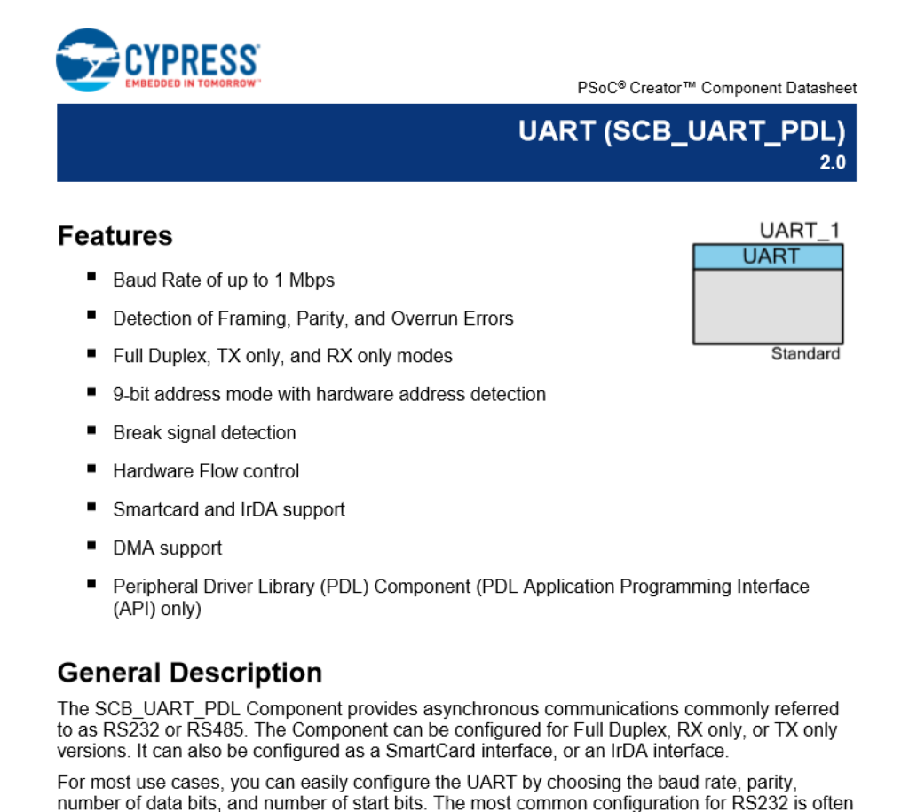
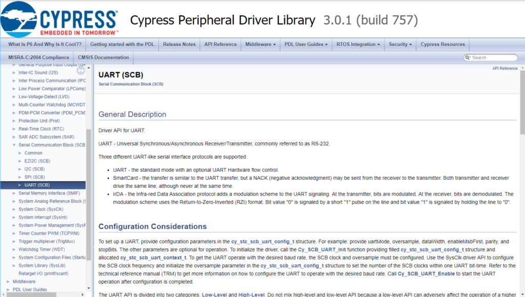
In the documentation I can see all kind of functions, including “Cy_TCPWM_PWM_Disable”

PSoC 6 PDL

Program and Test

PSoC 6 FreeRTOS Test

A Tour of PDL for the TCPWM

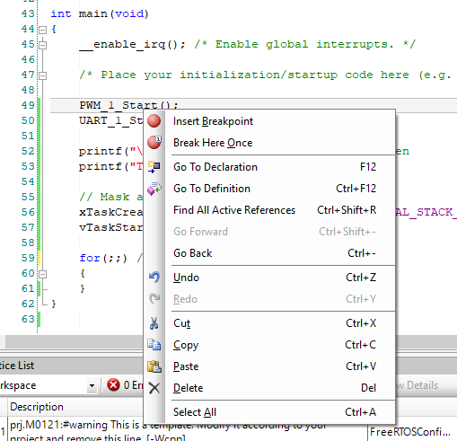
How did I figure out that the TCPWM_Type *base should be “UART_1_HW”?  ….. well …. You might ask yourself, “What does PWM_1_Start()” do?  It just calls PDL start function.  OK… so what does that do?  To find out you can right click on the “PWM_1_Start” function and select “Go To Definition” which will take you to the source code.

PSoC 6 Tour of PDL

You will end up in a file called “PWM_1.c”.  This file was created for you automatically by PSoC Creator.   This function is really simple.

  • If it has never been initialized then it calls init (lines 15-19)
  • Then it enables the TCPWM (line 22)
  • Then if there not an external pin on the PWM, then it causes a software trigger (line 25)
/*******************************************************************************
* Function Name: PWM_1_Start
****************************************************************************//**
*
*  Calls the PWM_1_Init() when called the first time and enables 
*  the PWM_1. For subsequent calls the configuration is left 
*  unchanged and the component is just enabled.
*
* \globalvars
*  \ref PWM_1_initVar
*
*******************************************************************************/
void PWM_1_Start(void)
{
    if (0U == PWM_1_initVar)
    {
        (void) Cy_TCPWM_PWM_Init(PWM_1_HW, PWM_1_CNT_NUM, &PWM_1_config);

        PWM_1_initVar = 1U;
    }

    Cy_TCPWM_Enable_Multiple(PWM_1_HW, PWM_1_CNT_MASK);
    
    #if (PWM_1_INPUT_DISABLED == 7UL)
        Cy_TCPWM_TriggerStart(PWM_1_HW, PWM_1_CNT_MASK);
    #endif /* (PWM_1_INPUT_DISABLED == 7UL) */    
}

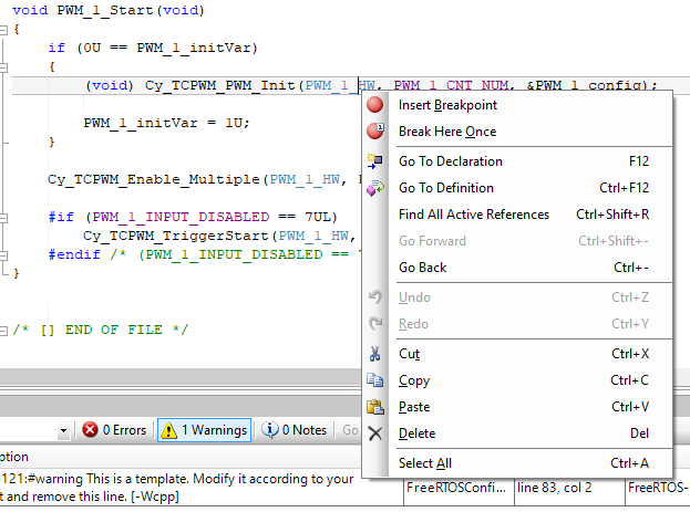
So, you might ask yourself what is “PWM_1_HW”?  Well this is just the base address of the registers for the PWM_1.  Lets follow that.  Right click on it and go to definition.

PSoC 6 PDL

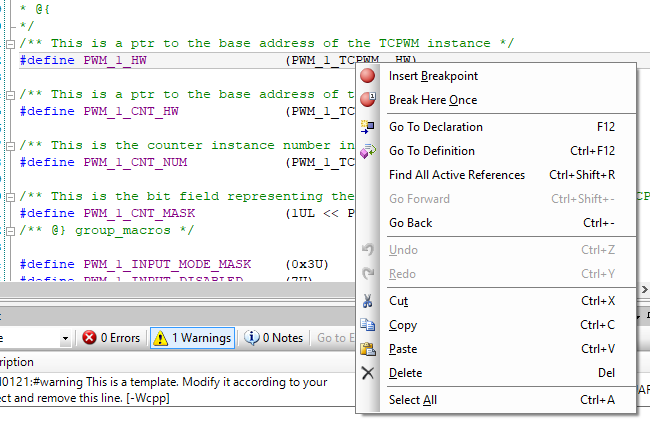
This will take you to PWM_1.h and you will see PWM_1_HW is setup as PWM_1_TCPWM_HW.  What is that?  Well do the right click thing again and find out.

/***************************************
*           API Constants
***************************************/

/**
* \addtogroup group_macros
* @{
*/
/** This is a ptr to the base address of the TCPWM instance */
#define PWM_1_HW                 (PWM_1_TCPWM__HW)

/** This is a ptr to the base address of the TCPWM CNT instance */
#define PWM_1_CNT_HW             (PWM_1_TCPWM__CNT_HW)

/** This is the counter instance number in the selected TCPWM */
#define PWM_1_CNT_NUM            (PWM_1_TCPWM__CNT_IDX)

/** This is the bit field representing the counter instance in the selected TCPWM */
#define PWM_1_CNT_MASK           (1UL << PWM_1_CNT_NUM)
/** @} group_macros */

#define PWM_1_INPUT_MODE_MASK    (0x3U)
#define PWM_1_INPUT_DISABLED     (7U)

PSoC 6 PDL

This will take you to “cyfitter.h” which is the output of the place and route.  It tell you that PWM_1_TCP is really TCPWM0

/* PWM_1_TCPWM */
#define PWM_1_TCPWM__CNT_HW TCPWM0_CNT0
#define PWM_1_TCPWM__CNT_IDX 0u
#define PWM_1_TCPWM__HW TCPWM0
#define PWM_1_TCPWM__IDX 0u


Lesson 2 – PSoC 6 Introduction: Your First Project
PSoC 6 Introduction

# Title Comment
0 A Two Hour PSoC 6 Class An introduction to the PSoC 6 class with links to all of the documents
1 Resources Links to all of the Cypress PSoC 6 information including videos, application notes etc.
2 Your First Project Learn how to build a PSoC 6 project and program your CY8CKIT-062-BLE development kit
3 FreeRTOS and a Debugging UART Build a project using FreeRTOS including a debug console with the UART
4 CapSense Build a project using the Mutual Cap Buttons and Self Cap Slider
5 Bluetooth Low Energy Build a CapSense project using BLE and CySmart

Since I did the webinar several things have happened

  1. Lesson 4: I fixed an error in the stack size for FreeRTOS
  2. Lesson 5: The PSoC Creator BLE PDL has been upgraded to greatly simplify the notifyCapSense function

All of the projects are available at git@github.com:iotexpert/psoc-6-introduction.git or www.github.com/iotexpert/psoc-6-introduction

Project Description

This will be your first PSoC 6 project. You will build a simple blinking LED project that uses an internal clock and a Pulse Width Modulator (PWM) to drive the RED LED on the CY8CKIT-062-BLE.

How does it work?

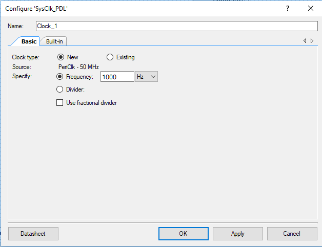
The PWM will take as input a 1 KHz clock and divide it by 1000 (period=1000) aka 1 Hz with a 50% duty cycle (compare = 500) to create an LED that blinks at 1 Hz.

How am I going to do it?

  1. Start PSoC Creator and tour the Workspace
  2. Make a new PSoC 6 project
  3. Walk through Workspace
  4. Create a schematic including assigning pins
  5. Write the firmware
  6. Program the PSoC 6 BLE

Start PSoC Creator

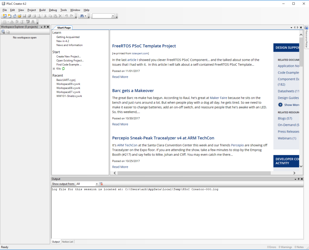
When you first run PSoC Creator 4.2 you will get a screen that looks like this:

PSoC Creator

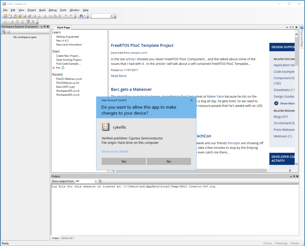
If you get a screen that looks like this, just click “No”.  This screen is asking for you to register the Keil Compiler and get a license.  This is only used for PSoC3

PSoC Creator Keil License

On the left is the Workspace Explorer which will contain all of the files & projects in your workspace… more to follow

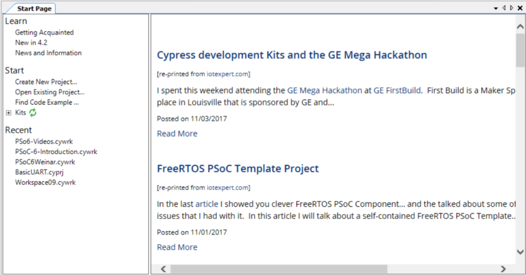
The Start page has a bunch of clickable links to take you to learning, new projects, etc.  It also has a web browser that shows the stream of posts from the Cypress PSoC Creator blog.

PSoC Creator Start Page

If you loose this screen you can bring it back by going to View –> Other Windows –> Start Page

PSoC Creator - Start Window

If your windows get screwed up you can always Window->Reset Layout

PSoC Creator Reset Layout

The Output window will contain messages from PSoC Creator including errors, compiler output etc… more to follow

Make a New PSoC 6 Project

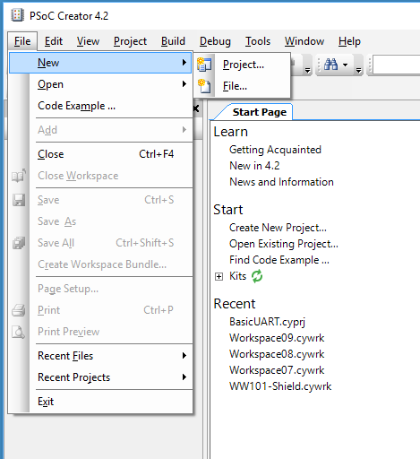
Start your first project with File –> New –> Project

PSoC Creator New Project

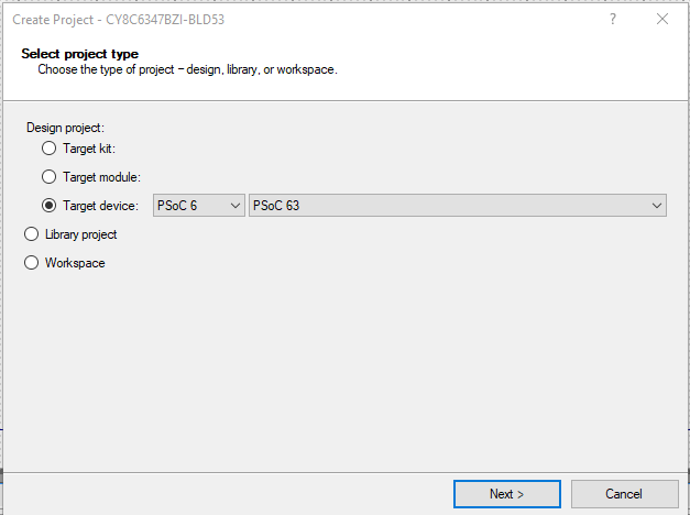
You need to choose to make a Design Project, a Library Project or a Workspace.  I want to make an actual design.  In order to know what chip the design is using I need to pick one of three options:

  1. Which development kit I have (PSoC Creator knows all of the Chips on the development kits)
  2. Which module (e.g. a bluetooth module)
  3. Which device

When you pick device it will let you start by picking the family (e.g. PSoC3/4/5/6) and then which specific device in the family.  The CY8CKIT-062-BLE has a PSoC 6 family PSoC 63 device on it.

PSoC Creator Specify Project Type

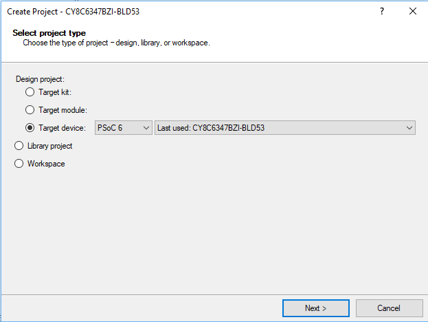
If you have previously built a project it will default to that device.

PSoC Creator New Project

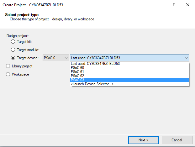
If you need to switch just use the pulldown menu

PSoC Creator New PSoC 6 Project

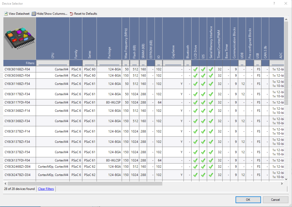
If you have some specific device, you can use the “device selector” which has all of the 50 million options.   The screenshot has a section of the PSoC 6 devices.PSoC Creator Device Selector PSoC 6

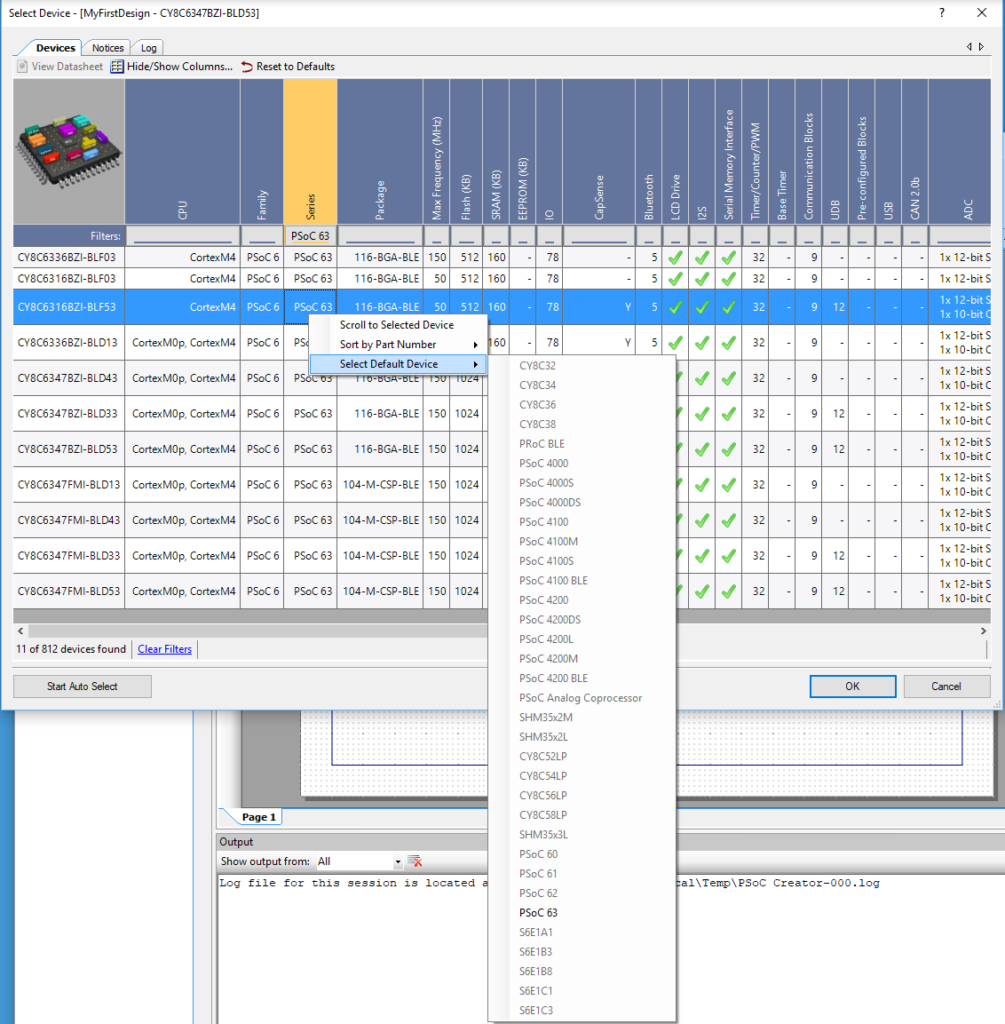
An excellent trick is that you can pick the default device by right clicking, then choosing “Select Default Device” and the family.  The default device will almost always be the device with all of the options that is installed on the development kit.

PSoC 6 Device Selector

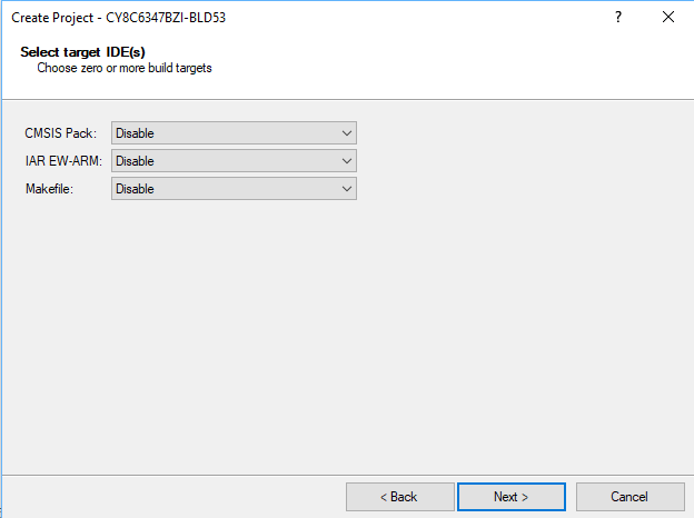
After the device is selected, you can setup the project to be exported to IAR, Keil, etc… (I am not going to show any of these but application note AN219434 talks about how to do it)

PSoC Creator Export IDEs

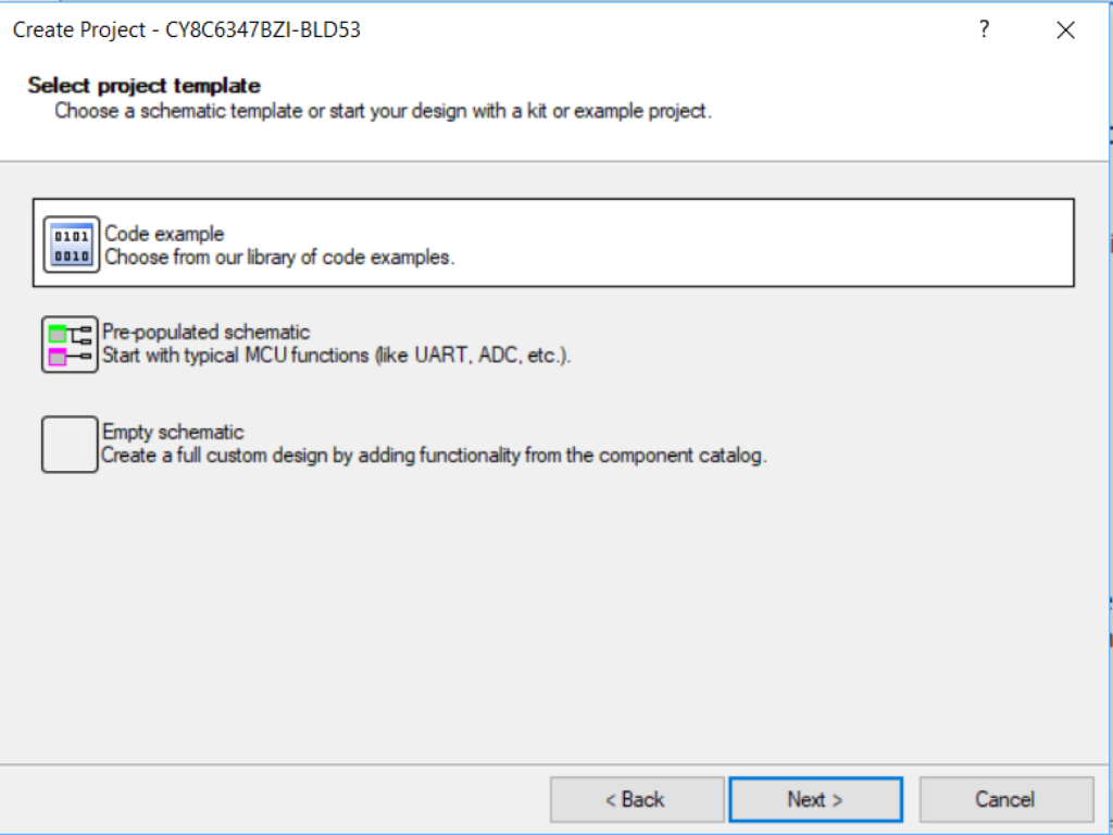
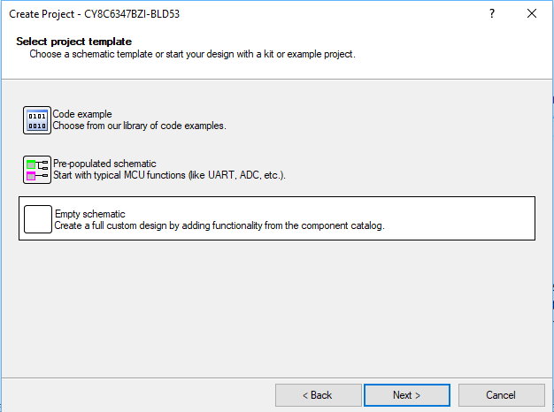
We give you the choice of building from a code example.

PSoC Creator Template

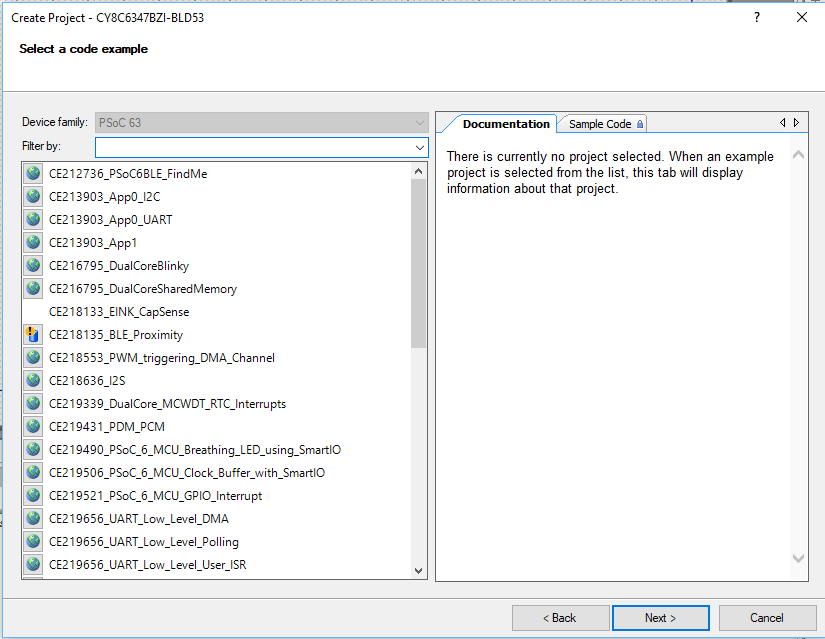
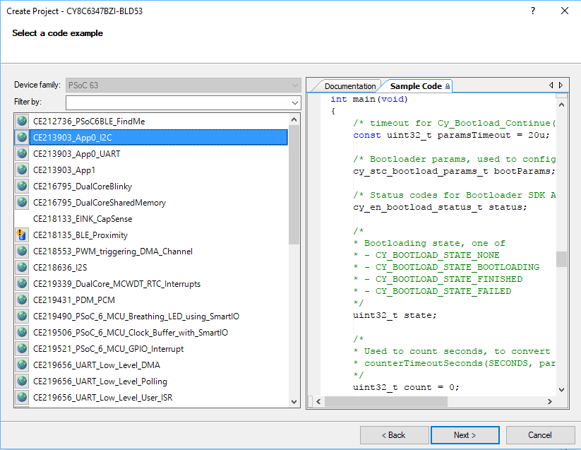
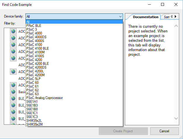
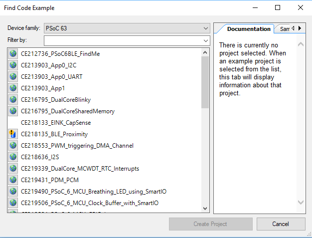
If you choose this option it will bring up the code example explorer

PSoC Creator Code Examples

If you click on a code example and the sample code tab in the window you can look and see how the firmware works without making a new project.

PSoC Creator PSoC 6 Code Examples

Or a pre-populated schematic which has a bunch of components that are already configured “normally” (whatever that means).  I tend to never do this, but it does prevent you starting with a blank project.

PSoC Creator PSoC 6 PrePopulated Schematic

Or an empty schematic (this is what I will do for all of the projects in this series)

PSoC Creator Empty Schematic

You need to specify the name of the workspace and the name of your project.

PSoC Creator New Project

Walk through Workspace

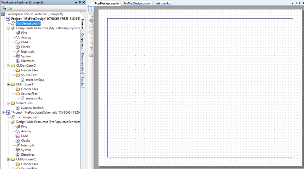
Starting with the Workspace Explorer.  PSoC Creator has the notion of a workspace which is a container for MULTIPLE projects.    When you double click any of the rows in the workspace explorer, PSoC Creator will open up that “File” for editing in the proper editor (code, schematic, etc)

Notice that in the picture below there are two projects.  The one in bold is called the “active” project… this is also known as the one that will program or build.  One of the great errors that people make is to edit a project other than the active one… then build and program… and then not understand why nothing is happening.

PSoC 6 Workspace Explorer

When you switch projects you need to right click on the project then select “Set As Active Project”

PSoC Creator Workspace Explorer

In the middle of the screen you will have a multiple tab thing.  Each tab represents one of the open documents.  There are different types of editors.  In the picture below you can see three documents are open.

PSoC Creator Schematic Editor

On the far right are the components that are available to be placed into your project. (more to follow).

PSoC 6 Component Catalog

Create a Schematic Including Assigning Pins

The first thing that I will do is make the blinking LED project.  The Hello World of MCUs.

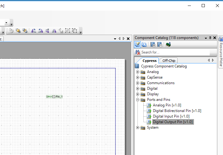
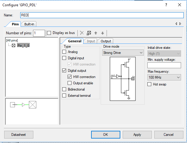
(1) Place a digital output pin by dragging and dropping it from the component catalog.

PSoC Creator PSoC 6 Digital Output Pin

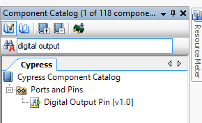
You can also find the digital output pin by typing into the search box

PSoC Creator Component Catalog

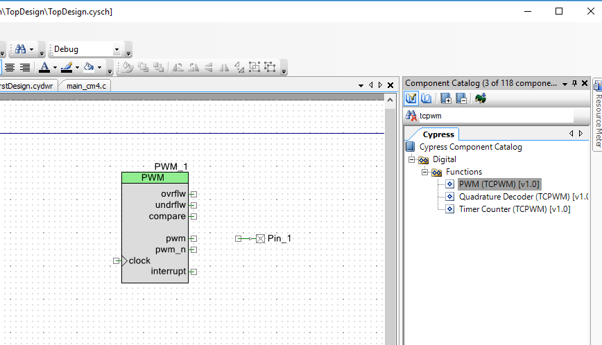
(2) Place a TCPWM

PSoC 6 TCPWM

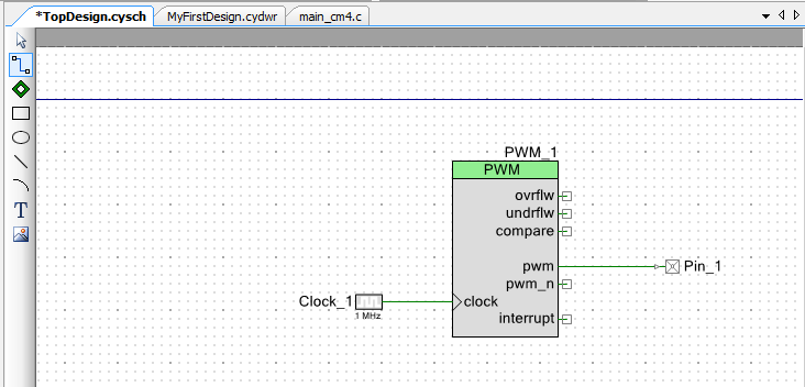
(3) Place a Clock

PSoC 6 Schematic

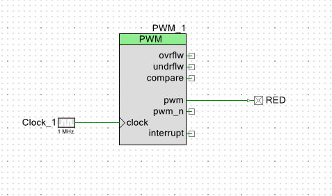
(4) Wire the three of them together (press the wire symbol under the pointer symbol) or press “w” on the keyboard.  Then click on the pin boxes.

PSoC 6 Schematic

(5) Configure the pin to be called “RED” by double clicking and change the name

PSoC 6 Digital Output Pin

Now the schematic should look like this:

PSoC 6 Schematic

(6) Configure the clock to 1000 Hz

(7) Configure the TCPWM Period to 1000 and the Compare to 500 (this will divide the input clock by 1000 which will make a nice even blinking 1 Hz LED)

(8) Assign the RED Pin to P0[3]

Here is a picture of that section of the CY8CKIT-062-BLE

Write the Firmware and Program

Click on Build –> Generate Application which will place and route the design and then bring in all of the required Peripheral Driver Library (PDL) functions into your project.  You can see all of the steps that PSoC Creator is executing in the “Output Window”

The next step is to edit the main c file.  There are two in this chip.  One called “main_cmop.c” for the Cortex-Mo Plus and one called “main_cm4.c” for the Cortex-M4

In order for the TCPWM to work you need to turn it on, with the “PWM_1_Start()” function call.  You can do this in “main_cm4.c” which you can edit by double clicking it.


Program the PSoC 6 BLE

You can build and program the design by

  1. Pressing the little chip button (just to the left of the debug bug)
  2. Pressing Ctrl-F5
  3. Selecting Debug->Program

When you click program, PSoC Creator will bring up a window that looks like this.  It shows that there are two ARM MCUs connected to the programmer.  It doesn’t matter which one you select as the programming target because they are both connected to the same Flash (remember it is a shared memory multi processor)

After you click OK, PSoC Creator will compile all of the file and then program the chip

As soon as it is done, you will see a message “Finished Programming” and ” … successfully programed …”  Then you should see the PSoC 6 LED start blinking. (yes that is my finger … sorry)

Lesson 1 – PSoC 6 Introduction: Resources

PSoC 6 Introduction

# Title Comment
0 A Two Hour PSoC 6 Class An introduction to the PSoC 6 class with links to all of the documents
1 Resources Links to all of the Cypress PSoC 6 information including videos, application notes etc.
2 Your First Project Learn how to build a PSoC 6 project and program your CY8CKIT-062-BLE development kit
3 FreeRTOS and a Debugging UART Build a project using FreeRTOS including a debug console with the UART
4 CapSense Build a project using the Mutual Cap Buttons and Self Cap Slider
5 Bluetooth Low Energy Build a CapSense project using BLE and CySmart

Since I did the webinar several things have happened

  1. Lesson 4: I fixed an error in the stack size for FreeRTOS
  2. Lesson 5: The PSoC Creator BLE PDL has been upgraded to greatly simplify the notifyCapSense function

All of the projects are available at git@github.com:iotexpert/psoc-6-introduction.git or www.github.com/iotexpert/psoc-6-introduction

Summary

This is an index with links to all of the PSoC 6 learning resources.  You can click the links to go the website or see screen captures of the resources.

  1. PSoC 6 Product Page
  2. PSoC 6 Documentation
  3. PSoC 6 Community
  4. CY8CKIT-062-BLE Development Kit Web Page
  5. CY8CKIT-062-BLE Development Kit Guide
  6. PSoC 6 Datasheet
  7. PSoC 6 Technical Reference Manuals
  8. Application Notes
  9. Videos
  10. Code Examples
  11. Knowledge Base
  12. PSoC Creator Help Page
  13. PSoC Creator Component Datasheet
  14. Peripheral Driver Library Documentation (Doxygen)

PSoC 6 Product Page

You can find the PSoC 6 Product landing page for PSoC 6 here

PSoC 6 Documentation

On the PSoC 6 Product Landing page there is a documentation tab that has links to all of the current documentation.

Community

Cypress has an active development community and forum.  It can be found here.

Development Kit Web Page

Every Cypress development kit has a web page that contains all of the information about it, including links to the documentation and store.  The CY8CKIT-062-BLE kit page is here.

CY8CKIT-062-BLE Development Kit Guide

PSoC 6 Datasheet

The PSoC 6 Datasheet is available on Cypress.com here.

Technical Reference Manual

Each of the PSoC 6 devices has a lengthy discussion of the Technical Resources.  These documents can be found here

Application Notes

You can get them all on our website… here is a link to the filtered list of PSoC 6 Application Notes.

The best application note is always the “Getting Started”.  In this case it is AN210781 “Getting Started with PSoC 6 MCU with Bluetooth Low Energy (BLE) Connectivity”

Code Examples

You can find all of the PSoC 6 code examples on the web.  In addition they are built into PSoC Creator.

Or in PSoC Creator:

Videos

Cypress has made a bunch of videos that take you step by step through an introduction to PSoC 6.  You can find them on the Cypress training website.

https://www.youtube.com/watch?v=vefexHmf_Us

Knowledge Base

The Cypress technical support team writes “Knowledge Base” articles when there are repeated issues reported by customers.  You can find them here.

PSoC Creator Help Page

There is a bunch of help on the PSoC Creator Help Page.

On the PSoC Creator Help page there are tons of resources including

PSoC Creator Component Datasheet

Every component in PSoC Creator can be right clicked -> datasheet

For example the datasheet for the UART

Peripheral Driver Library Documentation (Doxygen)

All of the APIs in the PDL are documented in a Doxygen generated HTML document.  You can get there from

  • Help -> Peripheral Driver Library (this link is live only when you have a PSoC 6 project open)
  • Right click on a component -> Open PDL Documentation

Lesson 0 – PSoC 6 Introduction: A Two Hour PSoC 6 Class

Summary

This is the top level web page for a two hour class about getting started with PSoC 6.  I was initially a bit worried about how much could be covered in only two hours… then I remembered how awesome PSoC Creator is at getting people going.  Originally, I was planning on writing a lab manual document describing all of the getting started exercises, but upon reflection, I decided to make a series of IoT Expert articles so that the content could be live.

I believe strongly that hands-on is best for real learning, so this class is built as four lab exercises for you to do by following along with my instructions.  I supplement the lab exercises with a survey of the PSoC 6 ecosystem… meaning all of the resources you can use to get help and learn.

You will need a few things for the class:

Todays virtual workshop agenda is as follows:

PSoC 6 Introduction

# Title Comment
0 A Two Hour PSoC 6 Class An introduction to the PSoC 6 class with links to all of the documents
1 Resources Links to all of the Cypress PSoC 6 information including videos, application notes etc.
2 Your First Project Learn how to build a PSoC 6 project and program your CY8CKIT-062-BLE development kit
3 FreeRTOS and a Debugging UART Build a project using FreeRTOS including a debug console with the UART
4 CapSense Build a project using the Mutual Cap Buttons and Self Cap Slider
5 Bluetooth Low Energy Build a CapSense project using BLE and CySmart

Since I did the webinar several things have happened

  1. Lesson 4: I fixed an error in the stack size for FreeRTOS
  2. Lesson 5: The PSoC Creator BLE PDL has been upgraded to greatly simplify the notifyCapSense function

All of the projects are available at git@github.com:iotexpert/psoc-6-introduction.git or www.github.com/iotexpert/psoc-6-introduction

PSoC Creator 4.2

The class is built on PSoC Creator 4.2 which is currently in beta.  Here is a screenshot (of the class workspace) that includes the example projects (which you can download).  It also shows that some of the components are still prototypes.  Don’t worry, Cypress will be releasing production silicon and final development software soon.

PSoC Creator

CY8CKIT-062-BLE

The class is built for the CY8CKIT-062-BLE.  Here is a picture of my development kit taken from the table at Starbucks where I am finishing the material for this class.

CY8CKIT-062-BLE PSoC 6 Development Kit

And here is the nice picture from our website (that the marketing guys made me use)

CY8CKIT-062-BLE

Leica A60S –> Leica S9I Microscope

Summary –

The article is the story of my new Leica S9I microscope.  A few years ago I bought a Leica A60 microscope from Microscope Central.  This was truly a game changing event in my engineering life, particularly the soldering part of my life.  It is a remarkable instrument… and it is amazing how much better you can see while using it.  If you have been following my articles, I am sure that you have seen it in the background of some of the pictures.  The only thing that I really really wished that it had was a camera.  It turns out that Leica never intended for it to have a camera, and in fact there is no good way to attach one.

Leica A60S

A couple of week ago, I started talking with a friend who is getting into electronics about it.  As I talked about the features etc, I started really wishing that I had a camera.  So I did a little bit of research and realized that Microscope Central had developed a camera attachment for the A60.  But after I talked with them about it, I didn’t really feel like it was a good solution for me as it attached over the eye pieces.  But it turns out that since I bought the Leica A60S, Leica had developed a new instrument called the Leica S9I (I stands for integrated camera).

Unboxing the Leica S9I

I couldn’t take not having a camera on my A60S, so I pulled the trigger and bought a Leica S9I.  And lookey here what I got from the nice UPS man yesterday.  I love that Leica Logo.

Leica S9I Box

The first thing was to put my Lab assistant Nicholas on the job.  Here he is working on the base.

Leica S9I Stand

Next, my lab assistant assembles the new telescoping mount – a nice feature that lets me swing the arm and raise and lower the microscope.

Leica S9I Swing Arm

After he got the base built he started on the Leica S9I microscope itself.

Unboxing the Leica S9I

Here is the stuff that came in the box.

  1. The Leica S9I microscope
  2. Two eye pieces (one fixed and one focusing)
  3. A remote control for the integrated Camera
  4. A bad ass LED light
  5. USB and HDMI cables.
  6. Power supply

Leica S9I Parts

After we (we=Nicholas) got it built he plugged the HDMI cable into the monitor on my desk and took a picture of the setup with the CY8CKIT-044.

Leica S9I First Screen Image

The back of the camera has

  1. HDMI (to attach to a monitor)
  2. SD (sd flash card)
  3. USB (to a computer)
  4. Ethernet

Leica S9I Back

The side of the camera has

  1. A power LED (red means booting, green means on)
  2. Three mode LEDs which show which output is active (Ethernet, USB or HDMI)
  3. A mode button (to switch between Ethernet, USB and HDMI)
  4. A take picture button

Leica S9I Side

Leica S9I Software

If you plug in Ethernet then you can control the camera with:

  1. A Mac OS Application called Leica Acquire
  2. An iOS Application called Leica Airlab
  3. A PC Application called Leica Application Suite

Here are a couple of screenshots of the Leica Acquire Application.  There is really not much going on with the application.  Basically you can adjust the camera settings and capture video and images.  That being said, I am not sure what else you might want to do.

Leica S9I and Leica Acquire

And zoomed in:

Leica S9I and Leica Acquire

And here is the shot when I clicked the camera button (not a screenshot but an acquired image)

Leica S9I and Leica Acquire

Here are two screenshots of the iOS App.  The first is of the image library in the App.

iOS Leica Airlab

This one is screenshot of the “live” view.  One thing that I am not in love with is the icons on the top of the screen are a bit awkward to use.  But once I got the hang of them it was OK.

iOS Leica Airlab

Here is a picture that I took in the iOS App of zoomed in section of the CY8CKIT-044

CY8CKIT-044

Here is are two pictures that I took with the iOS App.  The first is with the Development Kit flat on my desk, and the 2nd with the Development Kit tilted so you can read the laser mark on the CY8C4247AZI-M485.

PSoC 4200M PSoC 4200M

It took a little bit of time to get my eyeballs and the camera settings in sync.  Which was a bit annoying as the only thing that I can say that I don’t like about the Leica S9I is the stupid IR remote control for the camera sucks. The sucky remote control makes it a pain in the neck to get the camera menus configured.  I think that it is too bad that they didn’t put a Cypress Bluetooth device into the camera so that the system would work better.

All that being said.  Leica has always been the leader in optics, and based on my experience with this microscope, that leadership will continue far into the future.  One of the great things about this (and the A60) microscope is the Leica Fusion Optics.  The Leica engineers used an optical trick that is possible because the microscope is binocular.  We all remember from physics class that numerical aperture and magnification are intertwined to set resolution and depth of field.  Moreover, there is a tradeoff between numerical aperture and depth of field.  For soldering you want to have a super sharp image, and a big depth of field.  What Leica Fusion Optics does is present your eyes with two different images.  One that is super sharp, but with limited depth of field.  And the other that is less sharp but with more depth of field.  Then your brain magically combines them into one image that appear to have a giant amount of sharp depth of field.  You can read more about it on the Leica Microscope website.

Microscope Central

My final note in this whole thing is about Microscope Central.  Both times I looked for Microscopes I ended up buying from them.  This is a family owned business in Pennsylvania which made the transition to online at some point.  The first time I clicked on the little “online chat” button at the bottom of the screen it was a holiday Saturday and one of the Miller family answered … and was amazingly helpful in getting me on the right track for buying the A60S.  This morning I thought I would click there, and Scott Miller was there almost immediately.

This time they were awesome in helping me get switched to the Leica S9I.  They spent a bunch of time talking me through optics issues on the industrial microscopes.  Moreover he helped me spend money on things that matter.. e.g. Leica glass… but also helped my buy a much less expensive stand, which is very good as well.  All in all I find this remarkable because I am hardly a relevant customer, yet the treated me well.  I wouldn’t hesitate to buy from them again.

CY8CKIT-044 PSoC4200M Real Time Clock

Summary

In my article entitled “FreeRTOS FAT SL – Musing on my Implementation“, I lamented that I was supposed to implement a Real Time Clock so that the reads and writes of files could be timestamped, but didnt.  I knew that the PSoC4200M Real Time Clock is actually really easy to use.  But, I didn’t because I didn’t want to fix the command line interface that I was using.  In this article I will show you how to implement a PSoC4200M Real Time Clock in FreeRTOS.  Then in the next article Ill show you how to implement the FreeRTOS Command Line Interface to set the time and turn on the FreeRTOS FAT SL Clock Driver.

PSoC4200M Real Time Clock Schematic

The first thing to do is copy the FreeRTOS Template project.  Then add the UART and RTC components to the project schematic from the PSoC Creator Component Catalog.

PSoC4200M Real Time Clock Schematic

The PSoC4200M Real Time Clock will have the default settings for the component.

PSoC4200M Real Time Clock Configuration

To make an accurate clock, I want to turn on the Watch Crystal Oscillator which drives the Watch Dog Timers.  To do this, click on the “Clocks” tab of the Design Wide Resources.  Then press edit clock.

PSoC4200M Real Time Clock Configuration DWR

Once you are on the clock editor page, turn on the WCO (by pressing the checkmark in the upper left hand corner).  Then turn on the WDT Timer 0 in the Periodic Timer Mode.  Set the divider to 32768 so that the RTC will get 1 interrupt per second.  You also need to select the source of the RTC to be Timer 0.

PSoC4200M Real Time Clock Low Frequency Clock Configuration

Firmware

In the firmware I create a new task called “uartTask” which just starts the RTC, then prints out the time when the user presses ‘t’.  Obviously I didnt set the clock, so it starts from 12:00:00.  Ill fix that in the next post after I get the FreeRTOS Command Line Interpreter working.

void uartTask(void *arg)
{
    (void)arg;
    UART_Start();
    clearScreen();
    UART_UartPutString("Start Real Time Clock Demo\n");
    UART_SetCustomInterruptHandler(uartISR);
    uint32 timeBCD;
    char buff[32];
    
    RTC_Start();

    
    while(1)
    {
        ulTaskNotifyTake(pdTRUE,portMAX_DELAY);
        
        while(UART_SpiUartGetRxBufferSize()) // if there is data then read and process
        {
            char c;
            
            c= UART_UartGetChar();
			switch(c)
			{
                case 't':
                    
                    timeBCD = RTC_GetTime();
                    sprintf(buff,"%d:%d:%d\n",(int)RTC_GetHours(timeBCD),(int)RTC_GetMinutes(timeBCD),(int)RTC_GetSecond(timeBCD));
                    UART_UartPutString(buff);
                    
                break;

You can find this project called RTC-Example in the workspace PSoC-Filesystem on the IoT Expert GitHub site or git@github.com:iotexpert/PSoC-FileSystem.git