Summary
This article walks you through a PSoC 6 SDK example of measuring a pulse width using the TCPWM block’s counter function.
The Story
Recently I have been working with a Cypress guy and frequent collaborator Hassane. He is working on a project that includes some kind of sonic distance sensor (I am actually not sure which one). In order to “read” the sensor you need to be able to measure the width of a pulse which is easy enough to do using the TCPWM. I originally wanted to use the Cypress HAL to setup the PSoC 6 to do this function, but it is not yet enabled. So, I need to use PDL and the PSoC 6 Configurator.
Configure The TCPWM
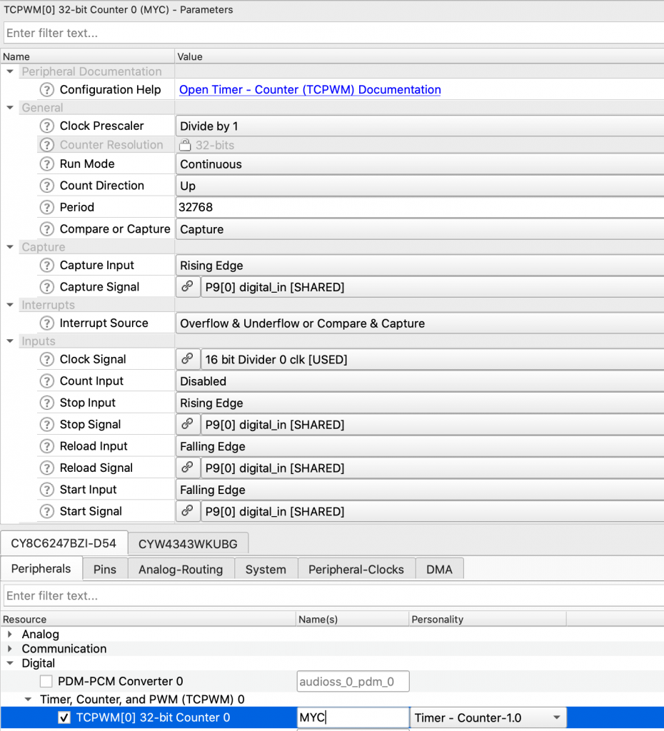
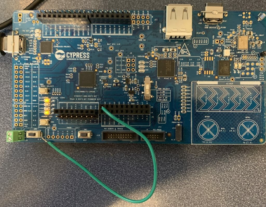
Start with a new PSoC 6 project. In my case I am using the CY8CKIT-062-WiFi-BT development kit because I had one where I had already soldered a wire onto the user switch. My plan is to create a “pulse” with the user switch, starting from the press, ending with the user letting go. This will be an active low pulse. I will configure the TCPWM to have start, reload setup as Falling edges. In other words the counter will reset and start counting when the button is pressed. Then I will setup Stop and Reload on Rising edges, in other words the timer will STOP and give an interrupt on the rising edge. All of these pins are connected to P9[0] on the PSoC.
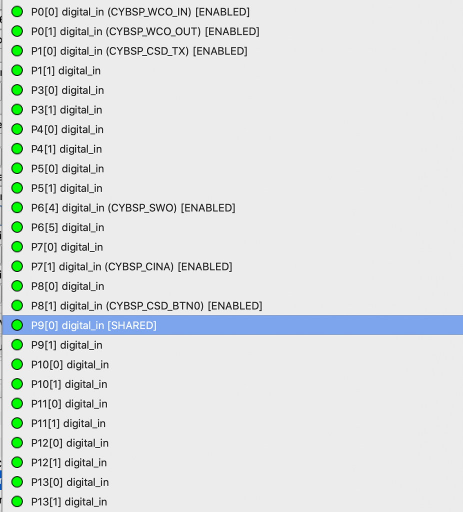
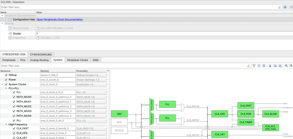
You might ask yourself, why P9[0]? That development kit has a switch connected to P0[4] seems like you should have connected the TCPWM to that pin. That was done because the TCPWM is only attached to a limited set of signals. Here is a screenshot from the configurator.
I want this setup to be interrupt based, specifically I want an interrupt when the Capture signal is active. It is also interesting when the counter rolls over (overflow). So I setup the interrupt source to be “Overflow & Underflow or Compare & Capture”.
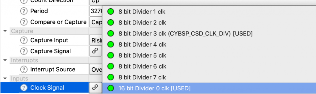
The last thing you need is a clock. you now need a clock. To do this clock on the Clock Signal. For this example I decided to use a 16-bit clock.
But what frequency is the input clock? To set this go to the “Peripheral-Clocks” The click on the divider you choose from above. Then pick a divide value. I choose 10000 which will give me 100MHz/10K=10KHz.
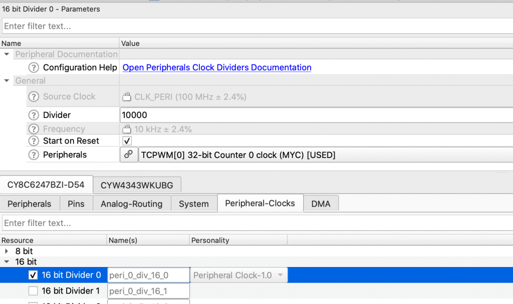
But where did the 100MHz come from? Click on the “System” and look at the clock diagram. All of the “Peripheral Clocks” use the signal “CLK_PERI” as their source. This is attached to CLK_HF0 (which is 100Mhz) in this case.
The Program
Once is everything is configured you need to write a bit of code.
9-14: First I create an ISR which will set a flag and clear the interrupt source in the TCPWM
Then I write a main function
20: Turn on the printf functionality using the cy_retarget_io library
25: Initialize the counter using the structure created by the configurator.
26: Then I enable the counter to run. Be careful with this function because counter numbers are NOT the same thing as counter masks. Counter 3 is counter mask 1<<3=8
28-30: Turn on the interrupts and register my ISR called counterDone
34: In the loop I wait around until the flag gets set by the ISR
36: Read the value from the counter and convert it to seconds
37: Print the value
38: Reset the flag
And do it all over again
#include "cy_pdl.h"
#include "cyhal.h"
#include "cybsp.h"
#include "cy_retarget_io.h"
#include <stdio.h>
volatile int flag=0;
void counterDone()
{
uint32 intCause = Cy_TCPWM_GetInterruptStatusMasked(MYC_HW,MYC_NUM);
flag = 1;
Cy_TCPWM_ClearInterrupt(MYC_HW,MYC_NUM,intCause);
}
int main(void)
{
cybsp_init() ;
cy_retarget_io_init(CYBSP_DEBUG_UART_TX, CYBSP_DEBUG_UART_RX, CY_RETARGET_IO_BAUDRATE);
__enable_irq();
printf("Started\n");
Cy_TCPWM_Counter_Init(MYC_HW,MYC_NUM,&MYC_config);
Cy_TCPWM_Enable_Multiple(MYC_HW,MYC_MASK);
cy_stc_sysint_t mycounter= {.intrSrc = MYC_IRQ, .intrPriority=7};
Cy_SysInt_Init(&mycounter,counterDone);
NVIC_EnableIRQ(MYC_IRQ);
for(;;)
{
if(flag == 1)
{
float val = (float)Cy_TCPWM_Counter_GetCounter(MYC_HW,MYC_NUM) / 10000.0;
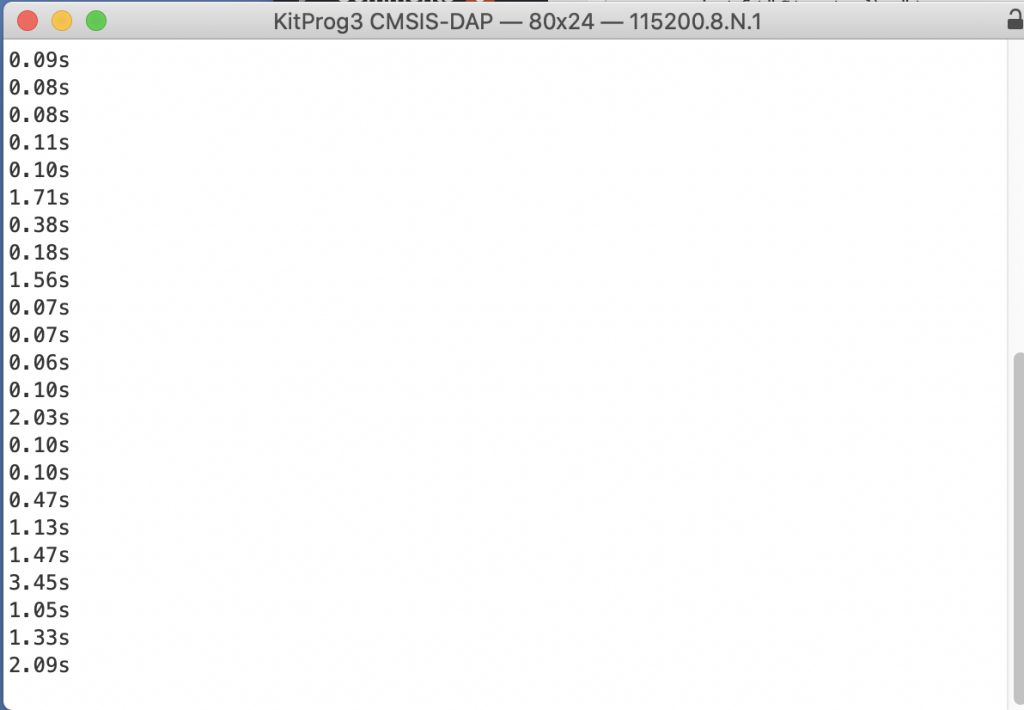
printf("%.2fs\n",val);
flag = 0;
}
}
}
Test
For an earlier article I had to solder a wire onto the switch. This let me attach it to an oscilliscope. It turns out that was an easy way to attach the switch to P9[0]
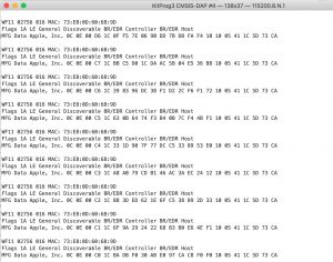
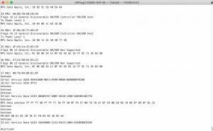
When I run the project I get a bunch of different pulse. Looks good.
No comment yet, add your voice below!