Summary
This article walks you through the steps to use the PSoC 6 MultiCounter Watch Dog Timer (MCWDT) as a DeepSleep Timer. This includes using the Cypress HAL (lptimer), PDL as well as the configurators to achieve this goal.
This article is part of the "PSoC 6 Low Power Techniques" Series which covers a range of tools you have to lower the power of your system. The following articles are (or will be) available:
| Articles |
|---|
| PSoC 6 Low Power |
| PSoC 6 & Using the MCWDT as a Deep Sleep Timer |
| PSoC 6 Deep Sleep Wakeup Time |
| PSoC 6 & FreeRTOS Tickless |
| Managing the PSoC 6 Clock Frequency |
| Using the PSoC 6 LDO and SIMO Buck Regulators for Low Power |
| Using the PSoC 6 Always on Backup Domain |
| PSoC 6 Turning off block of RAM |
The following resources are available
The Story
If you want to build a low power PSoC 6 project you need a method to wake up the chip from DeepSleep. This is particularly true of projects that use an RTOS in Tickless mode where you need a mechanism to go to DeepSleep and wakeup at a specific time. Why DeepSleep? Because it burns way-way less power than the active modes. Way less means something like 3 orders of magnitude less.
In this article I will
- Describe the MultiCounter Watch Dog Timer (MCWDT)
- Configure the MCWDT using the PSoC 6 Configurator
- Configure the MCWDT using PDL
- Configure the MCWDT using the HAL – AKA the lptimer
- Show the LP Timer Deep Sleep Current vs. Active Current
- Measure the Sleep Time & Show Interactions with DeepSleep and rest of the PSoC6
The Multi Counter Watch Dog Timer (MWCDT)
Inside of the PSoC 6 there are two blocks that have some variant of the name Watch Dog Timer. Specifically the:
- Multi Counter Watch Dog Timer (MCWDT)
- Watch Dog Timer (WDT)
Here is a screenshot from the PSoC 6 block diagram.
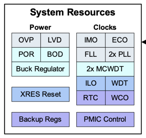
As I was working on this article I spoke with the original architect of the PSoC 6 and he told me that you should use the WDT as a WDT (but that it could be used as a periodic timer) and you should use the MCWDT as a periodic timer (but that it could be used as a WDT). This is a pretty common example of the Cypress design aesthetic of maximizing flexibility.
Bottom line: You should use the MCWDT as a deep sleep timer.
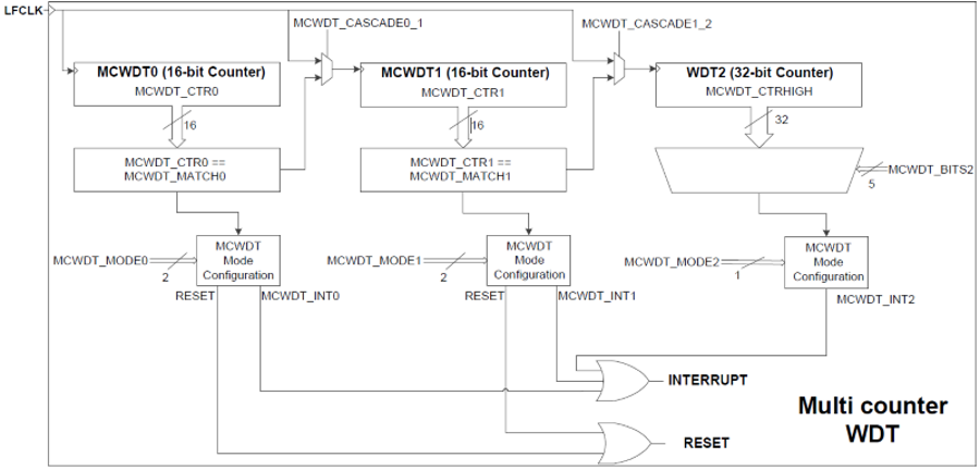
What is the MCWDT? It is actually three counters which can be used individually or cascaded. The counters each up count to a specific match value (aka period) and reset or they optionally count continuously. And each counter can generate an interrupt when the period is reached. The one “weird” thing is that counter 2 doesn’t have a match value, it has a match BIT position meaning it will match every 2,4,8,16… times depending on the bit position.
The counters are clocked by one of the 32kHz clocks in the PSoC 6 called “LFCLK” which can either be the WCO, the ILO or the PILO. This means that each “count” is 1/32768 = 30uS-ish
This means you can have
- 2×16-bit counters and 1×32 bit
- 2×32-bit counters
- 1×16-bit and 1×48-bit counter
- 1×64-bit counter
Here is a picture of the block diagram from the TRM.
PSoC 6 Configurator
For the first project I will use the PSoC 6 Configurators to setup the PDL configuration structures. I will make a project that will blink an LED at 1Hz. To do this I will configure counter 0 to turn 30.5uS into milliseconds and counter 1 to count 500 milliseconds. When counter 1 hits 500 it will toggle the LED.
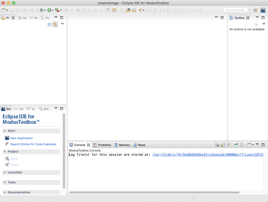
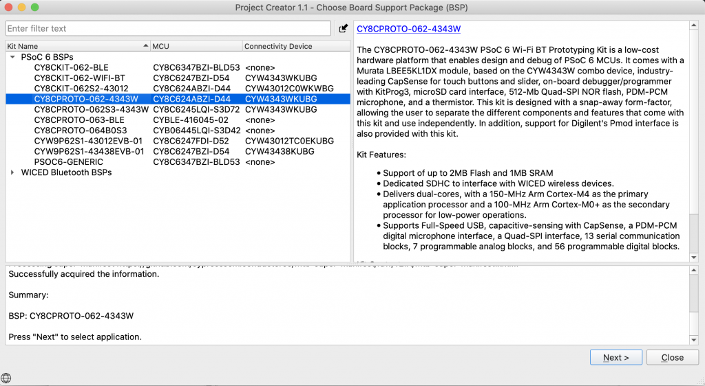
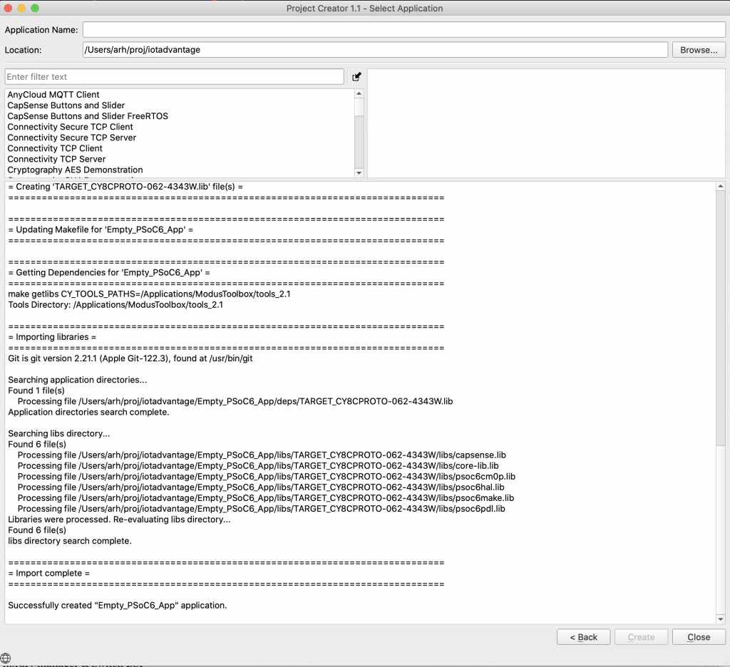
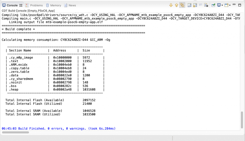
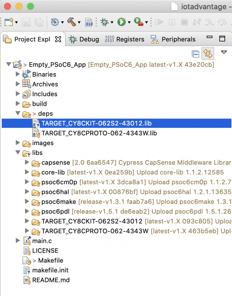
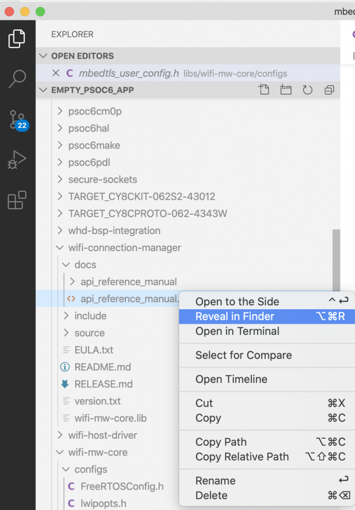
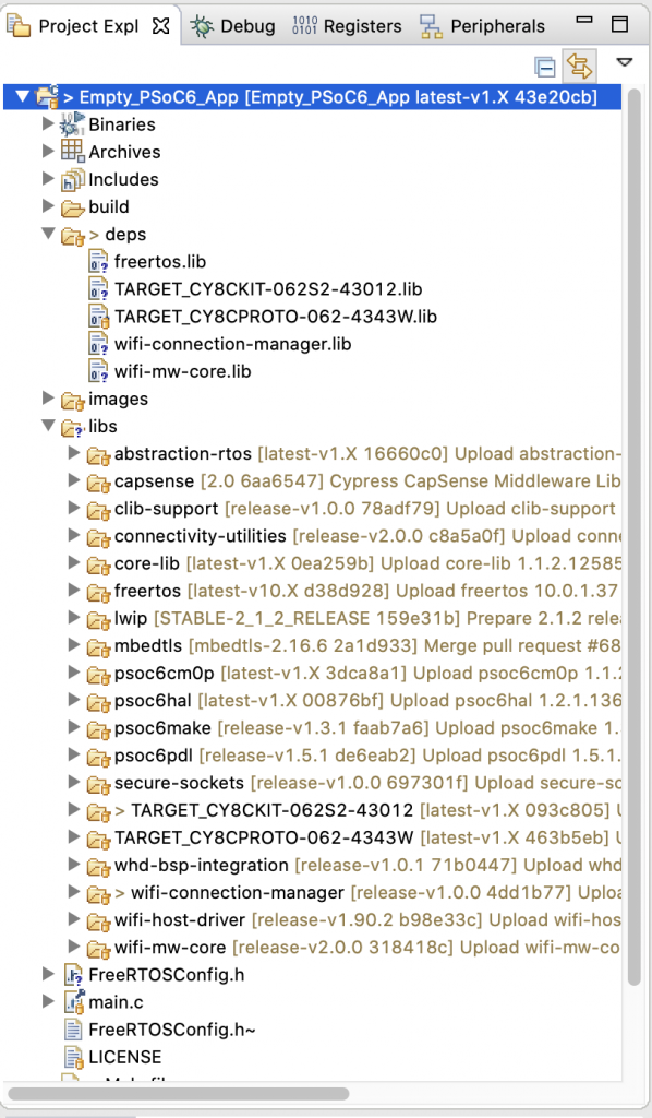
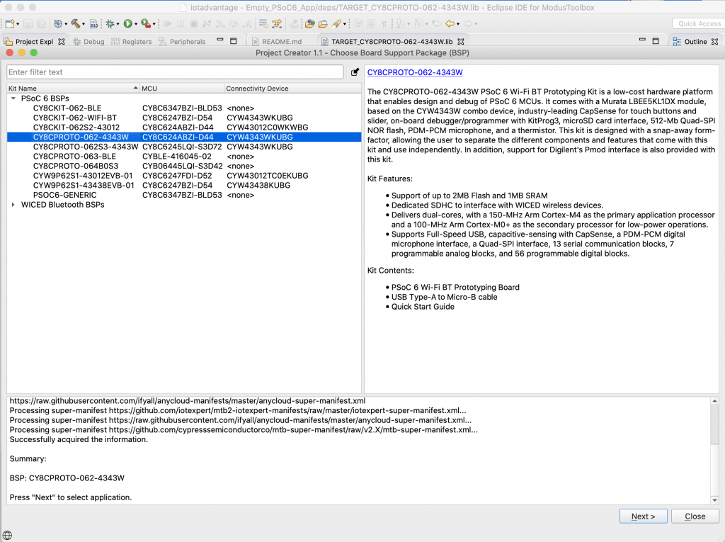
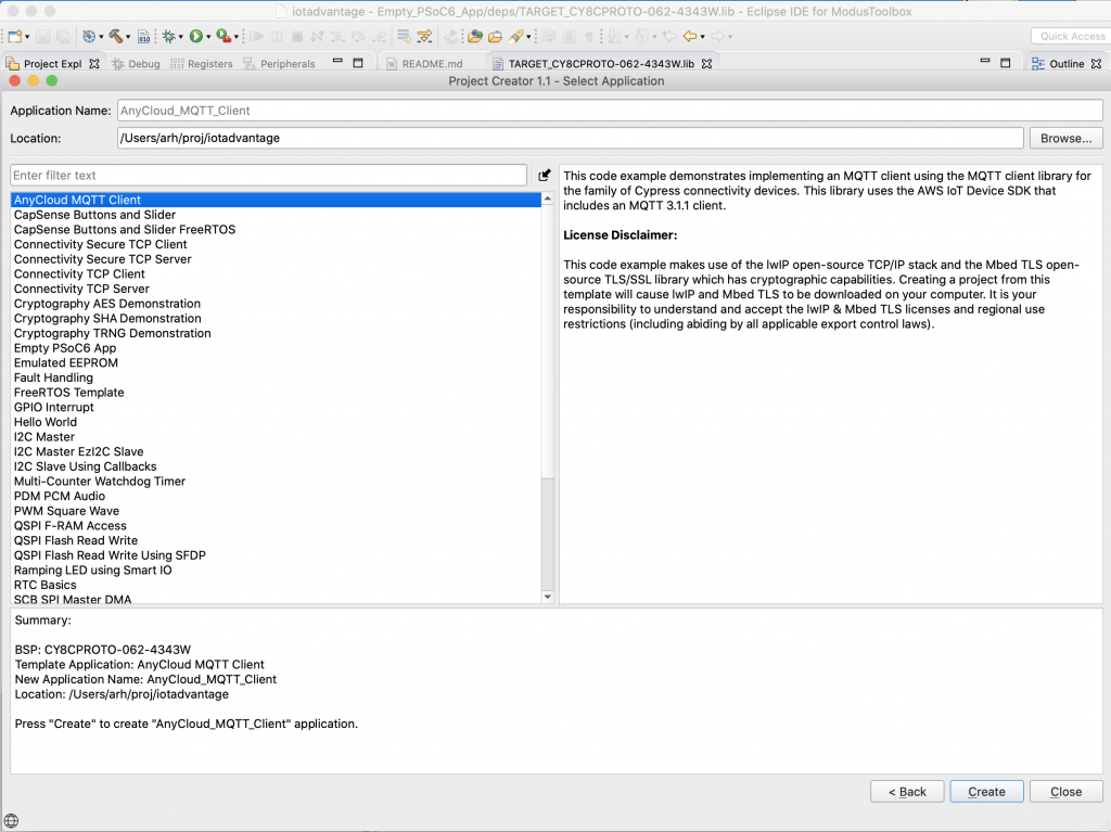
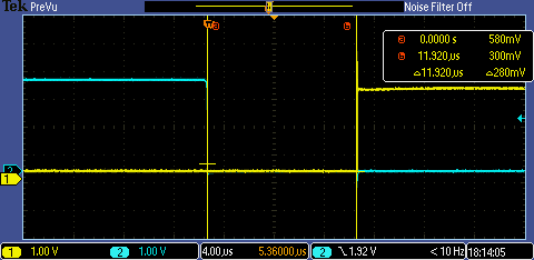
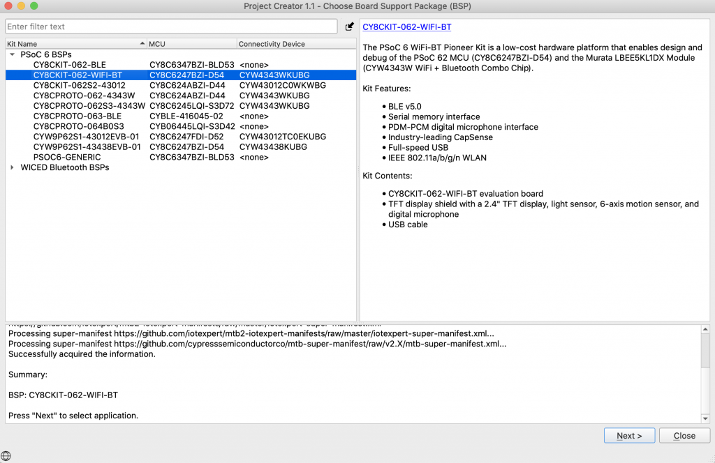
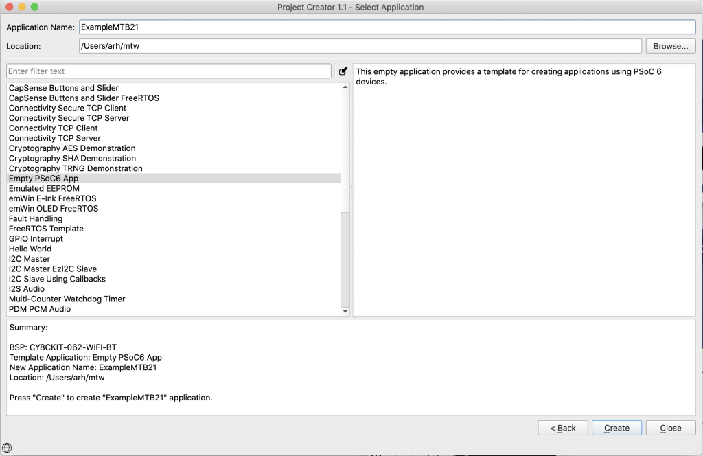
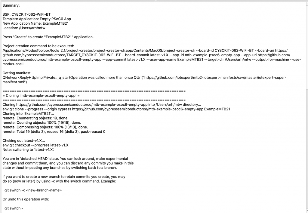
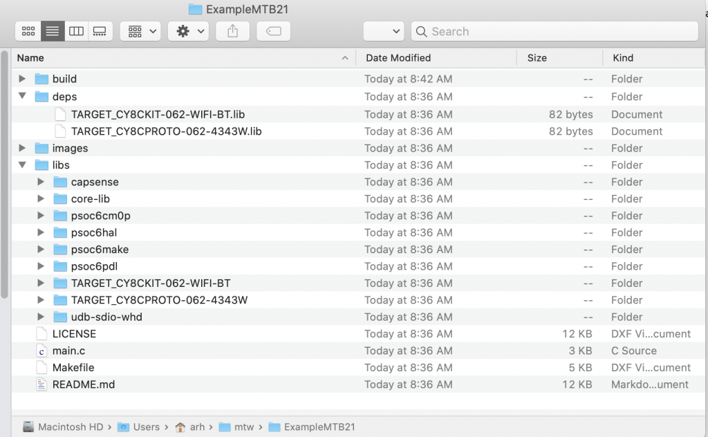
Start by making a new project:
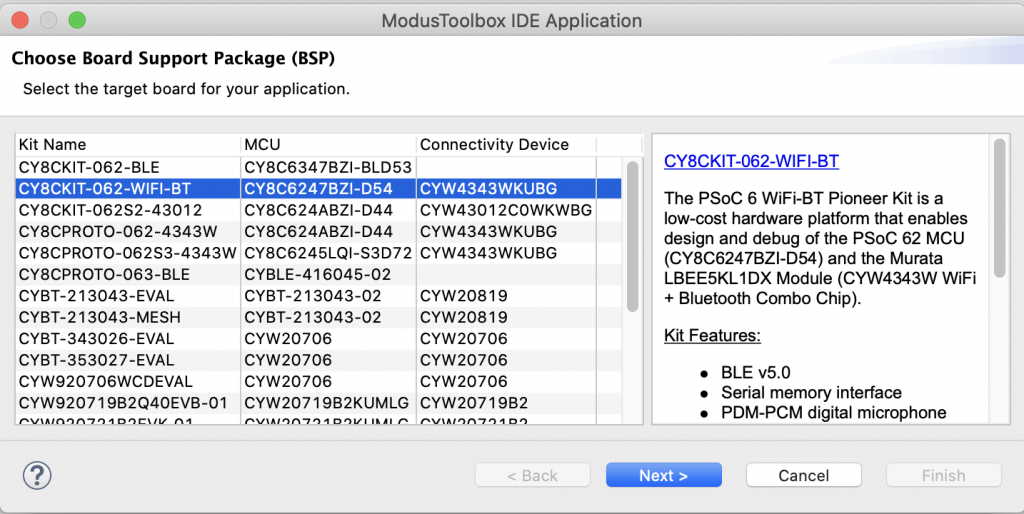
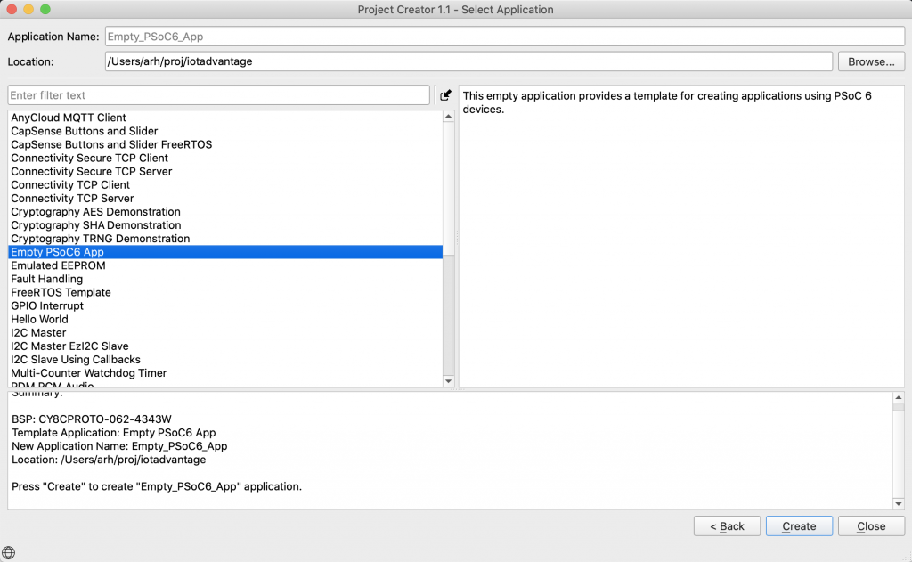
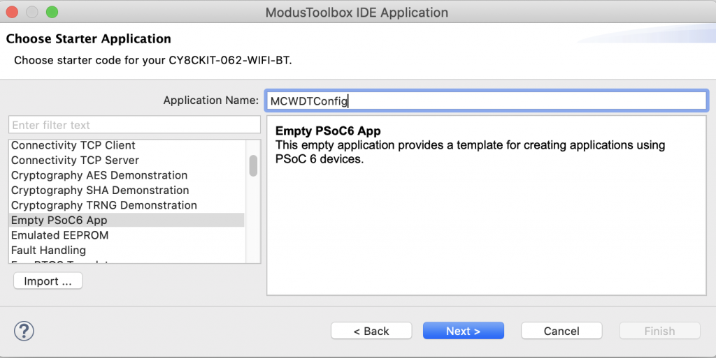
Give it a name and choose the Empty PSoC6 App as a template
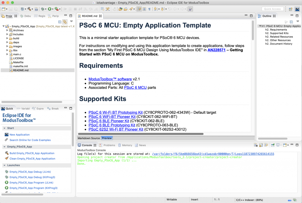
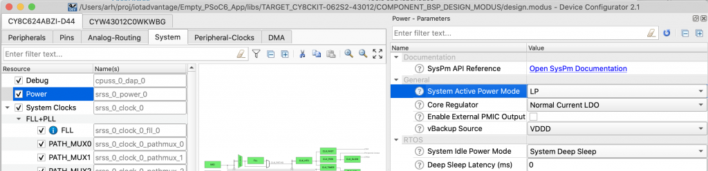
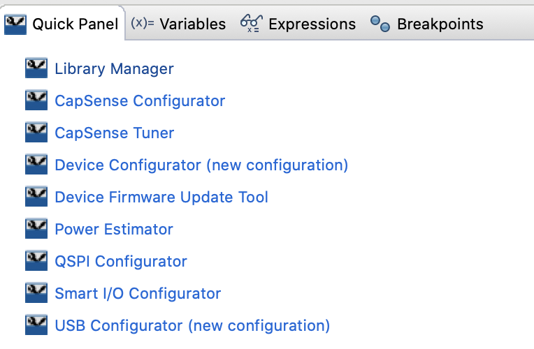
From the quick panel choose “Device Configurator (new configuration)”
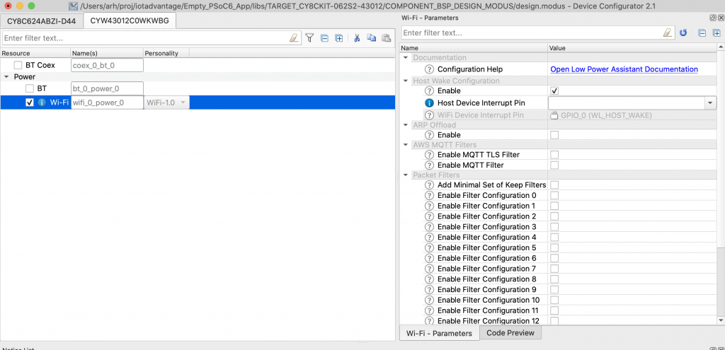
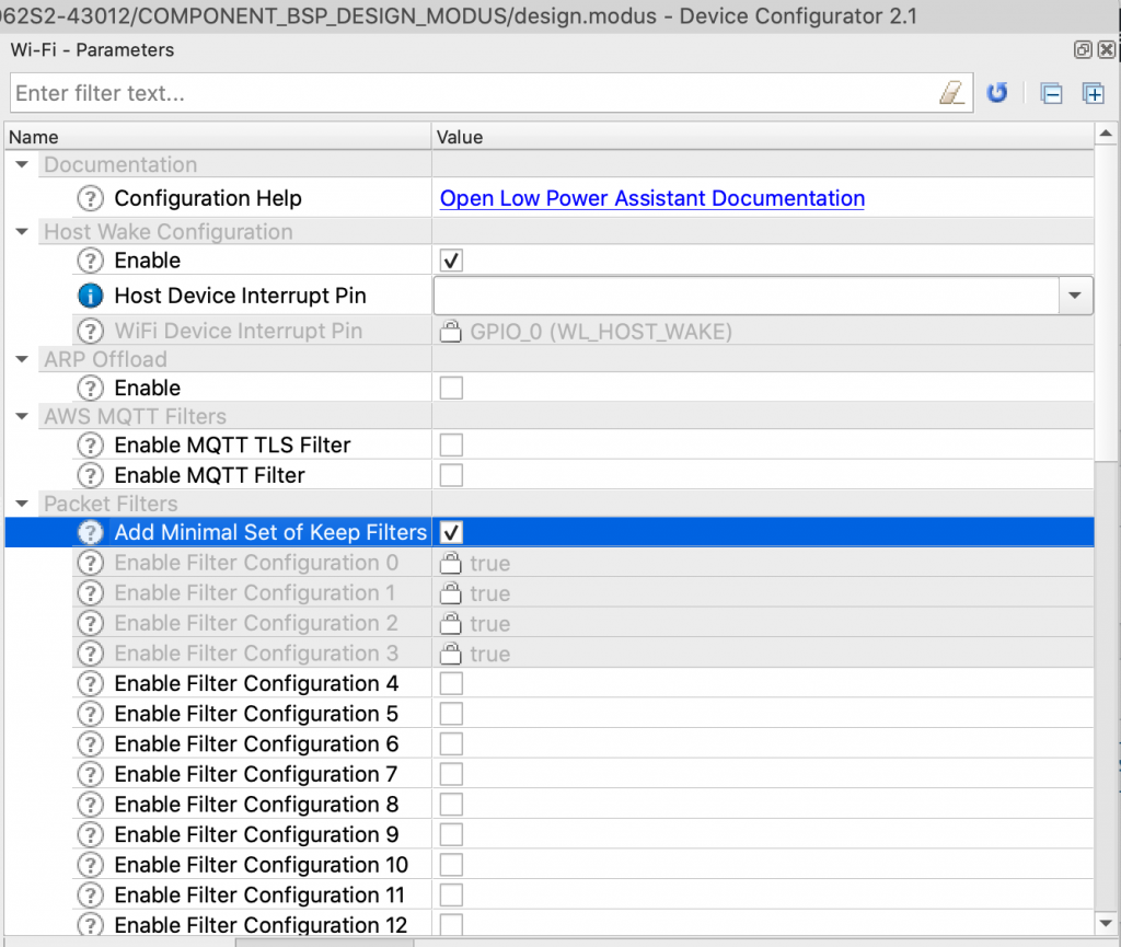
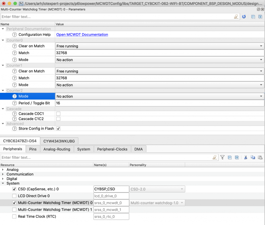
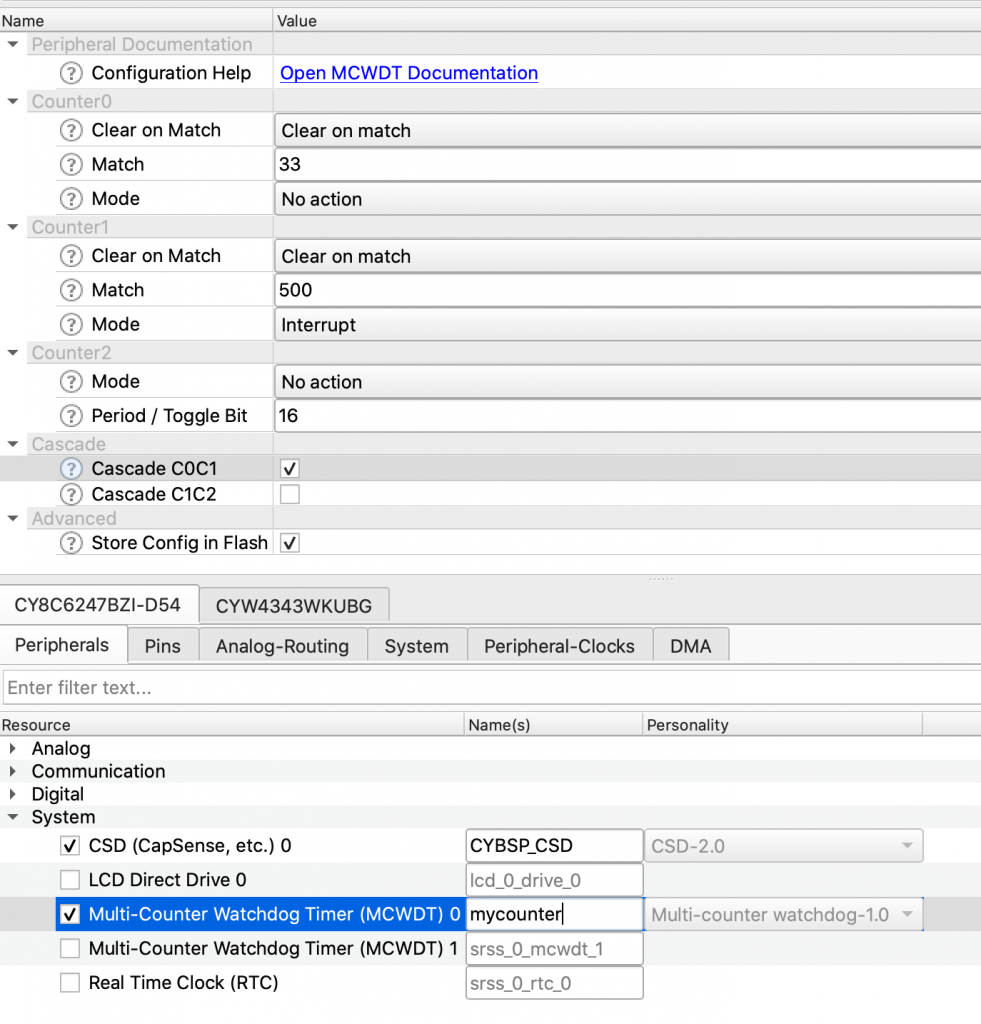
Then click on Peripherals –> System and enable Multi-Counter Watchdog Timer (MCWDT) 0.
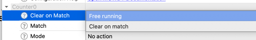
Notice that you can configure it to count up to the max then rollover (also known as Free running) or you can have it reset the counters back to 0 when it hits the match value (also known as Clear on match)
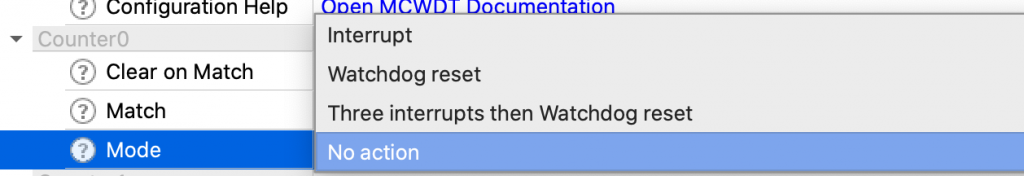
And when it his the end what do you want it to do? Interrupt, Watchdog reset, 3xWatchdog reset or nothing?
Here is the configuration we want for this example:
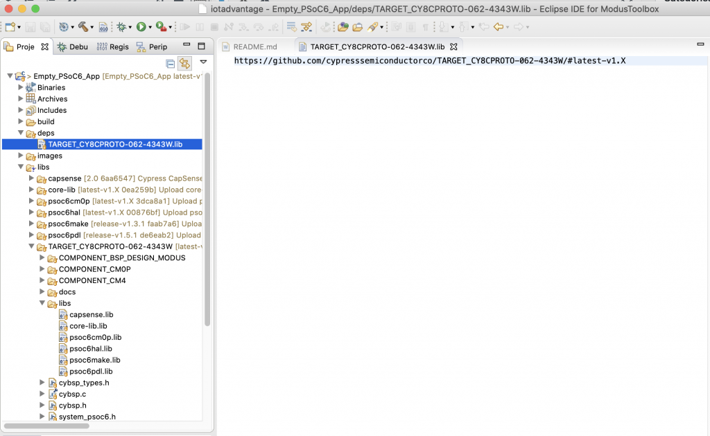
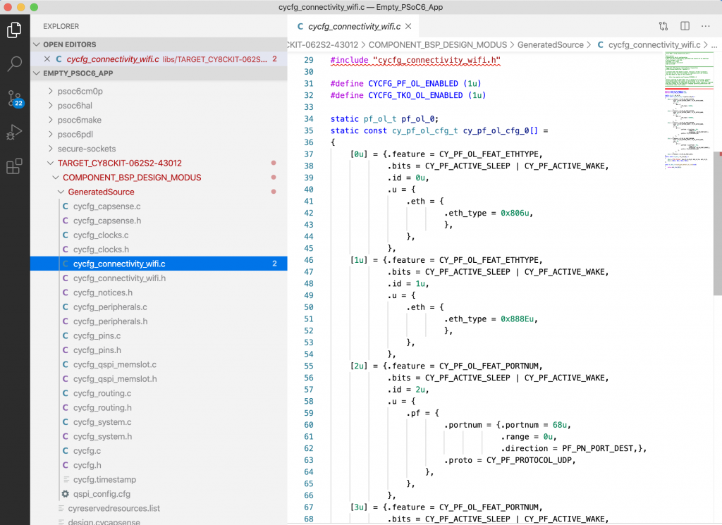
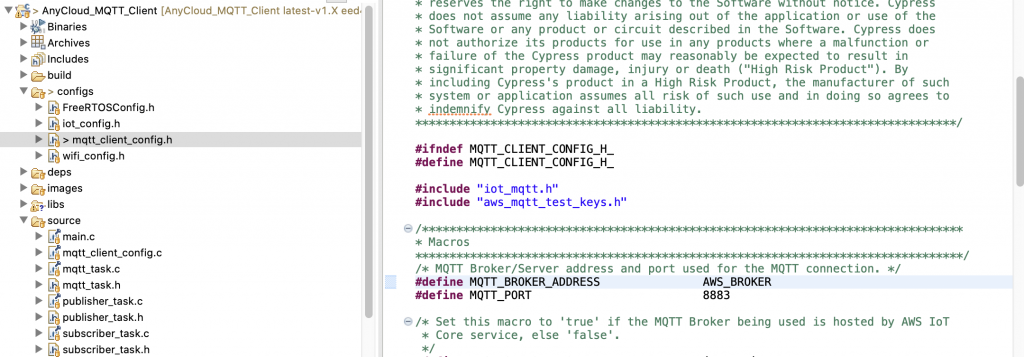
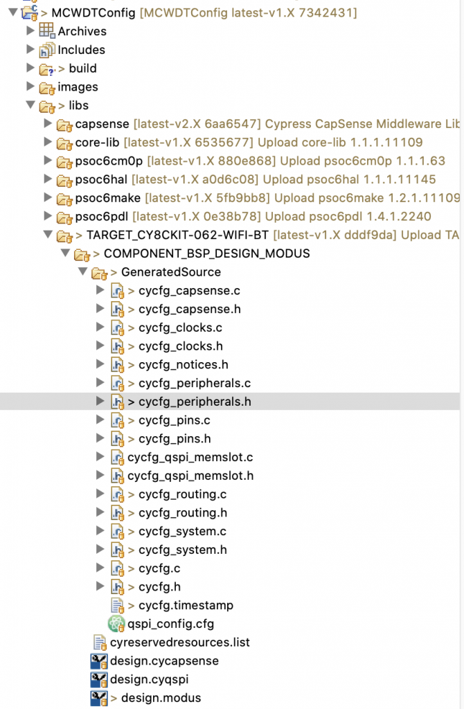
When you hit “save” the configurator will update the files in “libs->TARGET_CY8CKIT-062-WiFi-BT->COMPONENT_BSP_DESIGN_MODUS->GeneratedSource”. Specifically cycfg_peripherals.h/.c.
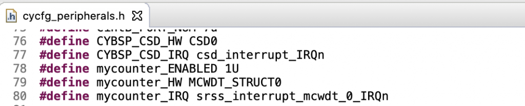
In the cycfg_peripherals.h it makes an #define alias called “mycounter_” which is sets you up for the MCWDT0
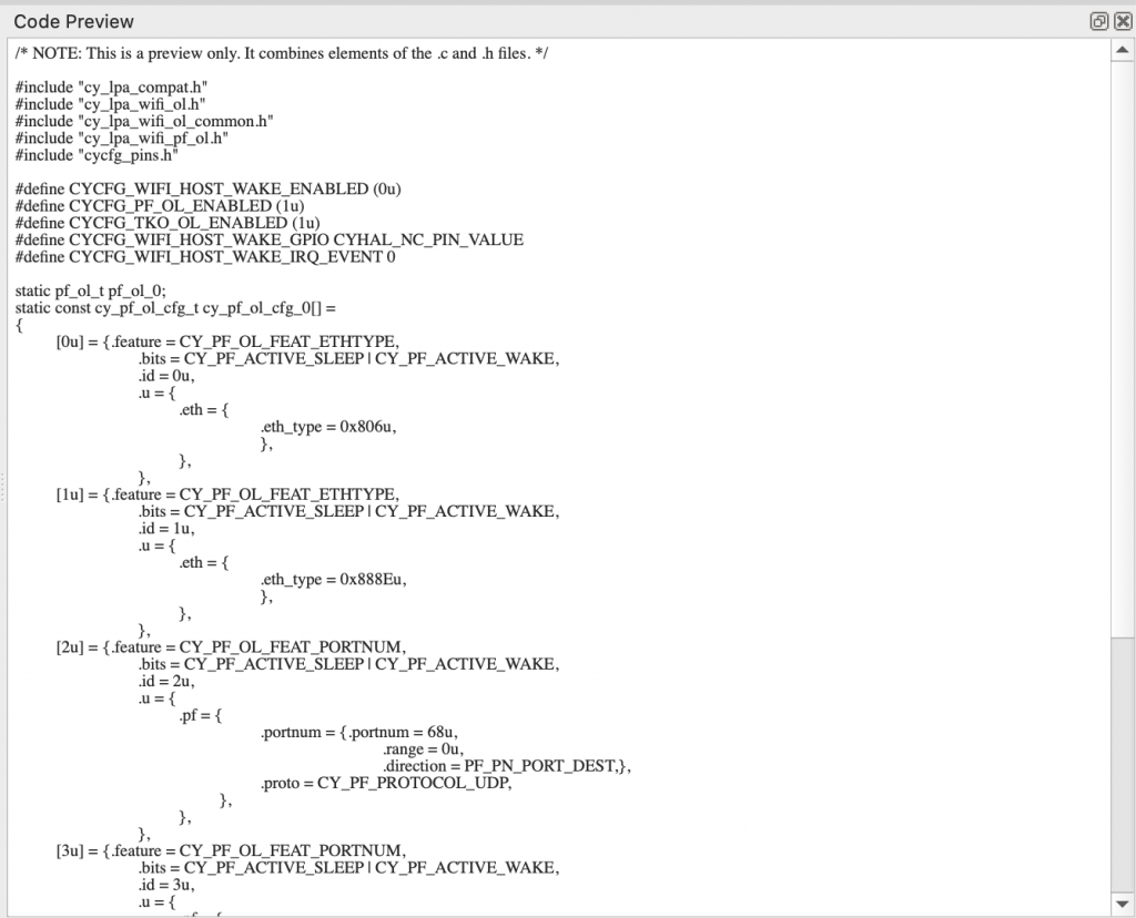
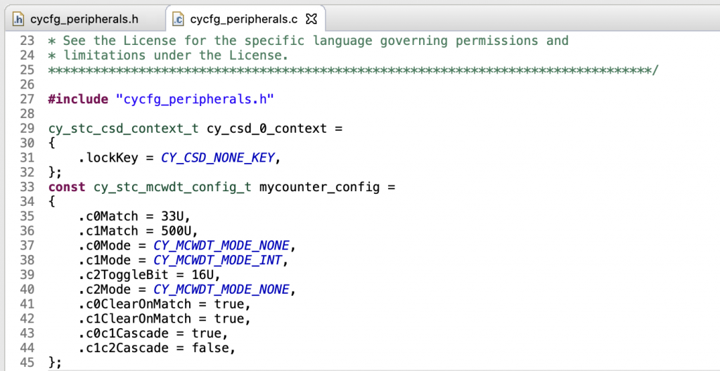
And in the cycfg_peripherals.c it sets up the configuration structure
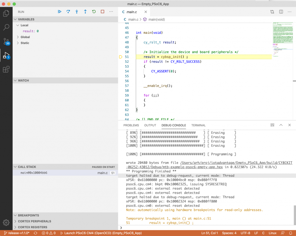
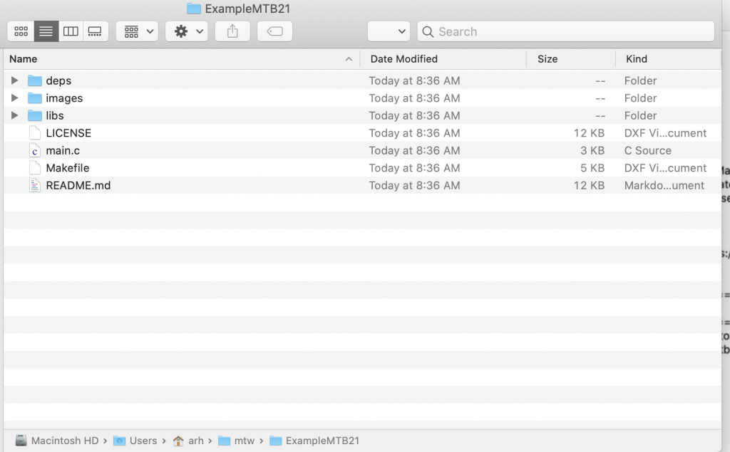
Now you can write this simple program in main.c
- Lines 5-9 provide an ISR that toggles the LED and clears the MCWDT interrupt. Notice that I assumed the interrupt was counter 1
- Lines 18-27 setup interrupts for the MCWDT0
- Lines 30-36 use the PDL configuration structure form the PSoC 6 configurator to setup the MCWDT
The main loop just goes into DeepSleep to save power.
#include "cybsp.h"
#include "cyhal.h"
#include <stdio.h>

void mcwdtISR()
{
	Cy_MCWDT_ClearInterrupt	(mycounter_HW,CY_MCWDT_CTR1);
	cyhal_gpio_toggle(CYBSP_USER_LED1);
}


int main(void)
{
	cybsp_init() ;

	cyhal_gpio_init(CYBSP_USER_LED1,CYHAL_GPIO_DIR_OUTPUT,CYHAL_GPIO_DRIVE_STRONG,1);

	cy_stc_sysint_t intrCfg =
	{
			.intrSrc = mycounter_IRQ,
			.intrPriority = 4UL
	};

	Cy_SysInt_Init(&intrCfg, mcwdtISR);
	NVIC_EnableIRQ(mycounter_IRQ);

	__enable_irq();


	Cy_MCWDT_Unlock(mycounter_HW);
	Cy_MCWDT_Disable(mycounter_HW, CY_MCWDT_CTR0 | CY_MCWDT_CTR1, 100);

	Cy_MCWDT_Init(mycounter_HW,&mycounter_config);
	Cy_MCWDT_SetInterruptMask(	MCWDT_STRUCT0,	CY_MCWDT_CTR1	);

	Cy_MCWDT_Enable(mycounter_HW, CY_MCWDT_CTR0 | CY_MCWDT_CTR1 , 100);

	for(;;)
	{
		Cy_SysPm_DeepSleep(CY_SYSPM_WAIT_FOR_INTERRUPT);
	}
}
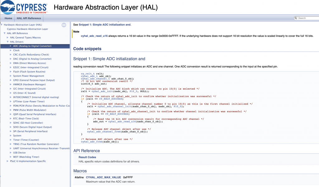
Basic HAL LP Timer
Obviously you can do all of the PDL stuff… but we also provide a higher level abstraction called the “LPTIMER” which does all of the configuration for you. To demonstrate this I create the same program except using the HAL. This program will use the LPTIMER and an event to blink the LED at 1hz (toggle every 500ms).
The main.c has:
- Lines 9-12 a simple function to turn milliseconds into ticks of the MCWDT (remember it is clocked with 32KHz)
- Lines 14-18 is the event handler function which is called when the LPTIMER expires. All it does is toggle the LED and reset the timer to MSDELAY
- Lines 26-29 setup the LPTimer, enable the interrupt event, register the callback function and then set the timer
The main loop just goes to DeepSleep.
#include "cy_pdl.h"
#include "cyhal.h"
#include "cybsp.h"

#define MSDELAY 500

cyhal_lptimer_t myTimer;

static inline uint32_t msToTicks(uint32_t ms)
{
	return (uint32_t)(CY_SYSCLK_WCO_FREQ*(ms/1000));
}

void lptimer_event(void *callback_arg, cyhal_lptimer_event_t event)
{
	cyhal_gpio_toggle(CYBSP_LED8);
	cyhal_lptimer_set_delay(&myTimer, msToTicks(MSDELAY));
}

int main(void)
{

	cybsp_init() ;
	cyhal_gpio_init(CYBSP_LED8,CYHAL_GPIO_DIR_OUTPUT,CYHAL_GPIO_DRIVE_STRONG,1);

	cyhal_lptimer_init(&myTimer);
	cyhal_lptimer_enable_event (&myTimer, CYHAL_LPTIMER_COMPARE_MATCH, 4, true);
	cyhal_lptimer_register_callback(&myTimer, lptimer_event, 0);
	cyhal_lptimer_set_delay(&myTimer, msToTicks(MSDELAY));

	__enable_irq();

	for(;;)
	{
		cyhal_system_deepsleep();

	}
}
LP Timer Deep Sleep Current vs. Active Current
For the next project I will use the LPTIMER to demonstrate the DeepSleep current versus the Active Current. This project:
- Will use LED8 to indicate DeepSleep and LED9 to indicate Active
- Go to DeepSleep for 2 seconds (so you can read the power)
- Wait in a busy-wait loop for 2 seconds
- Loop again
The main.c has:
- Lines 8-12 a simple function to turn milliseconds into ticks of the MCWDT (remember it is clocked with 32KHz)
- Lines 17-18 Setup the two LEDs to indicate the power state
- Lines 20-21 initialize the low power timer. Notice that you can enable the event (which will wakeup the chip) but you don’t have to provide an event handler. The LPTIMER ISR will handle clearing the interrupts for you
- Lines 27-29 will setup the LPTIMER delay, turn on LED8 and off LED9 and go to DeepSleep
- Lines 31-32 will turn off LED8 and on LED9 then go into a busy wait loop.
Notice that I did two three things weren’t aren’t awesome:
- I hardcoded the 0/1 for the LED state (they are active low)… this is too bad since the BSP actually provides CYBSP_LED_STATE_ON
- I put two LED set on the same line (two statements on the same line is super dangerous)
- No comments (yes Hassane will make commentary on this)
#include "cyhal.h"
#include "cybsp.h"

cyhal_lptimer_t myTimer;

#define MSDELAY 2000

static inline uint32_t msToTicks(uint32_t ms)
{
	return (uint32_t)(CY_SYSCLK_WCO_FREQ*(ms/1000));
}

int main(void)
{
	cybsp_init() ;

	cyhal_gpio_init(CYBSP_LED8,CYHAL_GPIO_DIR_OUTPUT,CYHAL_GPIO_DRIVE_STRONG,1);
	cyhal_gpio_init(CYBSP_LED9,CYHAL_GPIO_DIR_OUTPUT,CYHAL_GPIO_DRIVE_STRONG,1);

	cyhal_lptimer_init(&myTimer);
	cyhal_lptimer_enable_event (&myTimer, CYHAL_LPTIMER_COMPARE_MATCH, 4, true);

	__enable_irq();

	for(;;)
	{
		cyhal_lptimer_set_delay(&myTimer,msToTicks(MSDELAY));
		cyhal_gpio_write(CYBSP_LED8,0);	cyhal_gpio_write(CYBSP_LED9,1);
		cyhal_system_deepsleep();

		cyhal_gpio_write(CYBSP_LED8,1);	cyhal_gpio_write(CYBSP_LED9,0);
		Cy_SysLib_Delay(MSDELAY);

	}
}
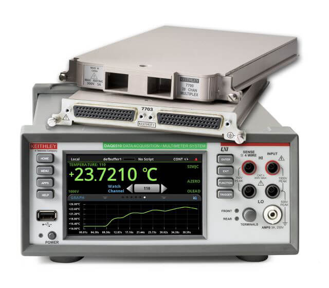
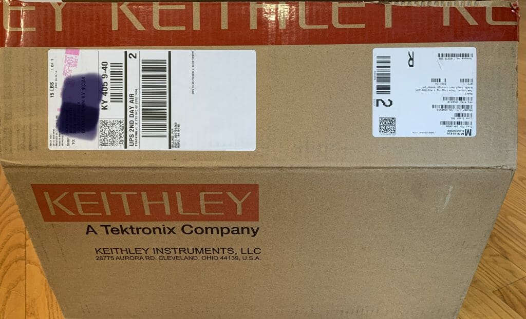
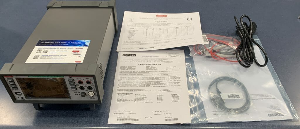
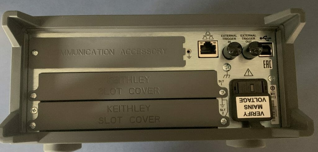
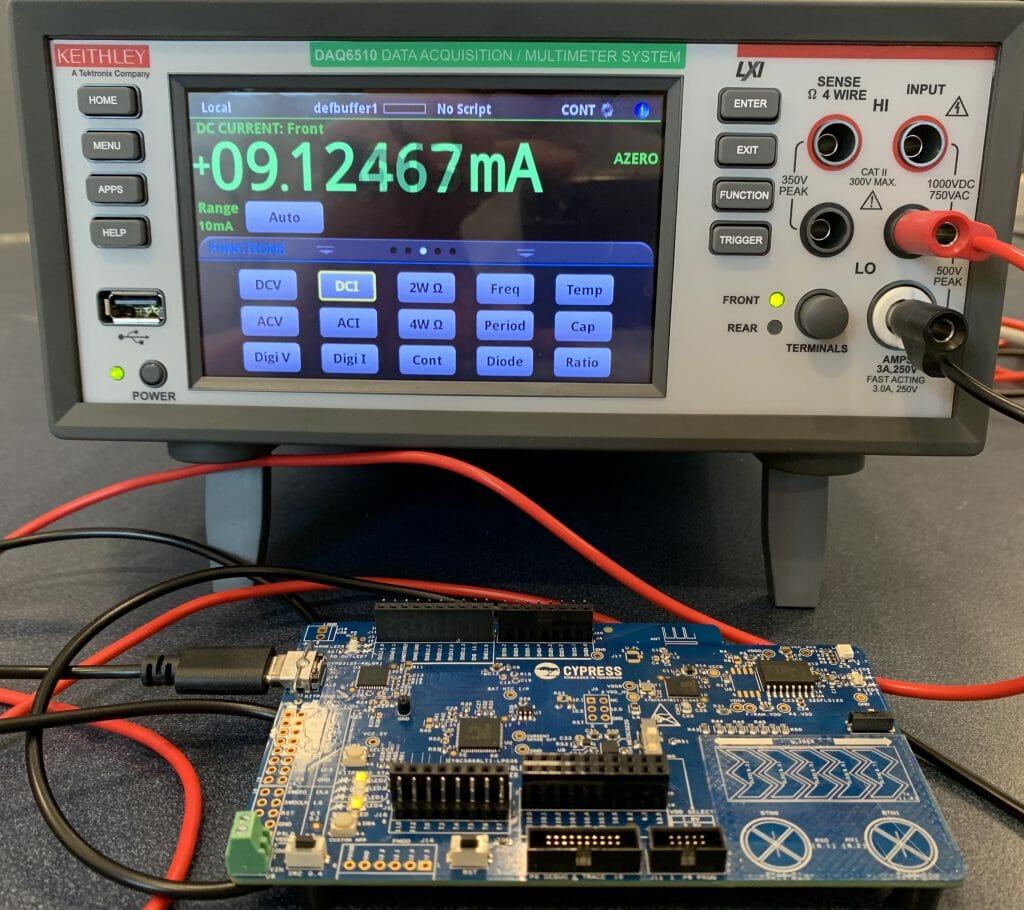
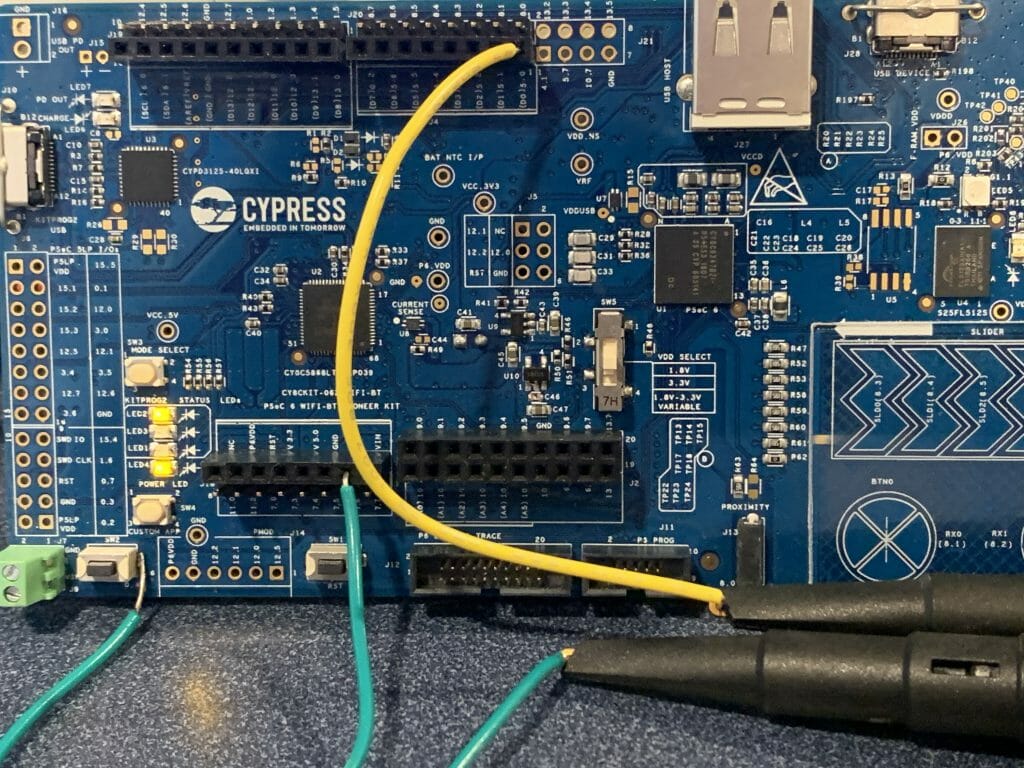
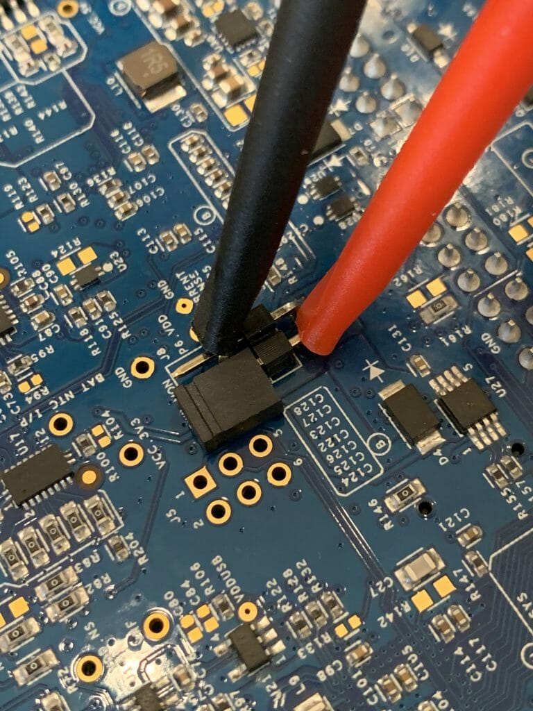
On the back of my development kit I setup the multimeter to be in series with the PSoC 6 power. Notice that I keep from loosing the jumper by attaching it to only 1 of the pins.
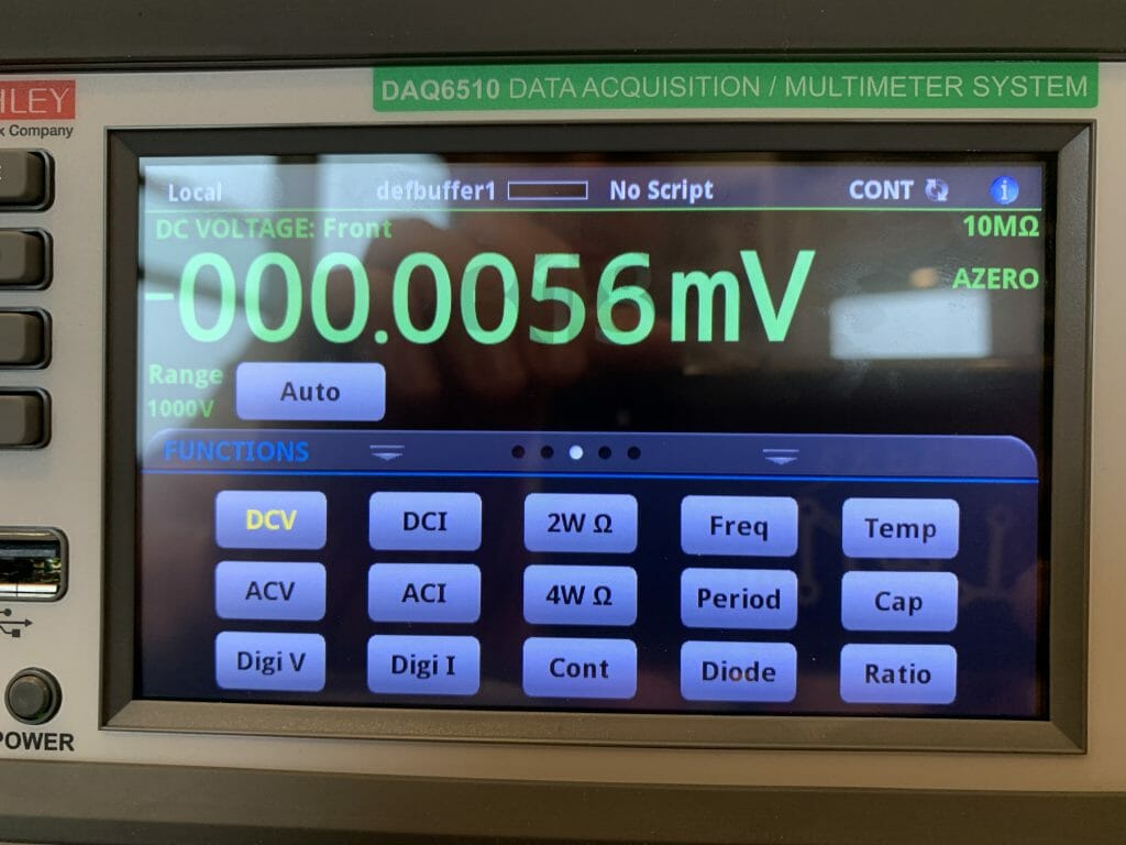
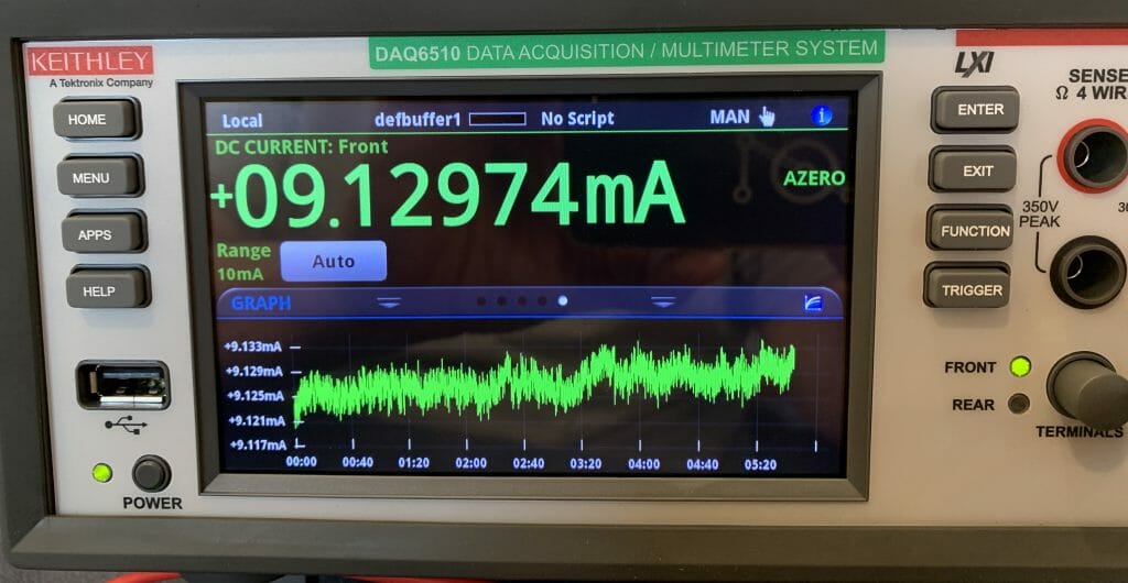
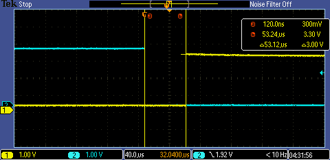
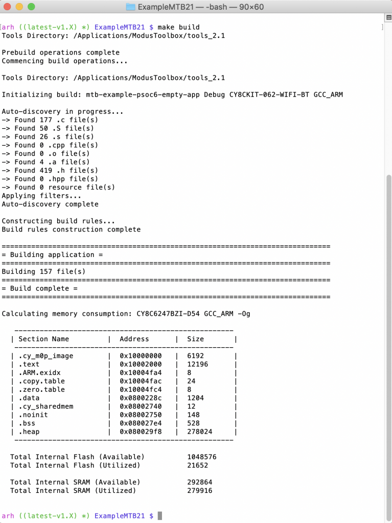
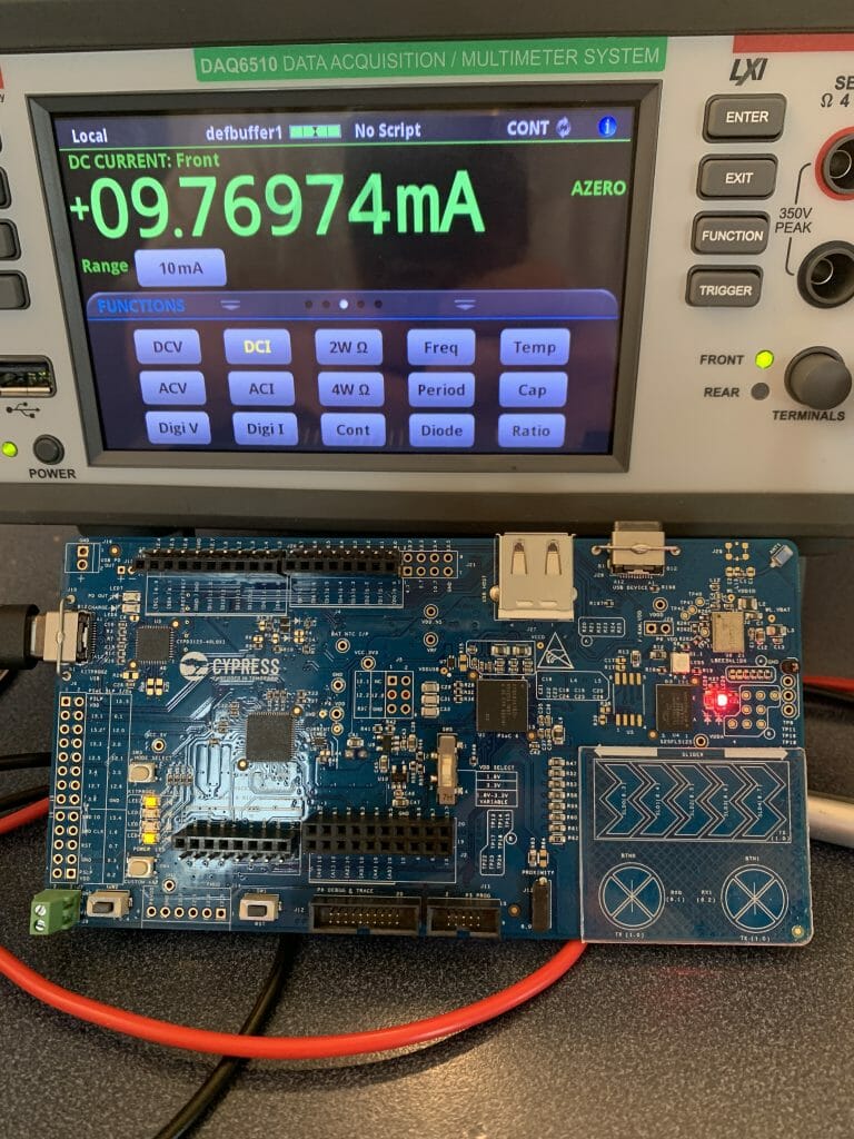
When I measure the power I get Active power of about 10mA
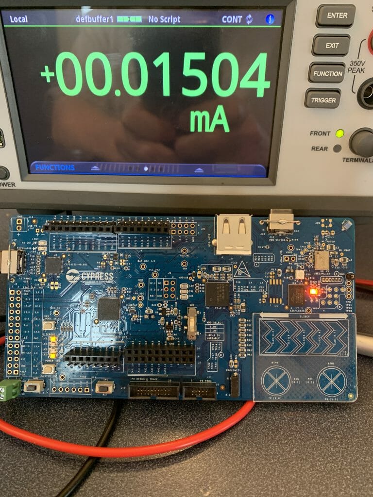
And DeepSleep power of 15uA… that’s cool almost 1000x difference.
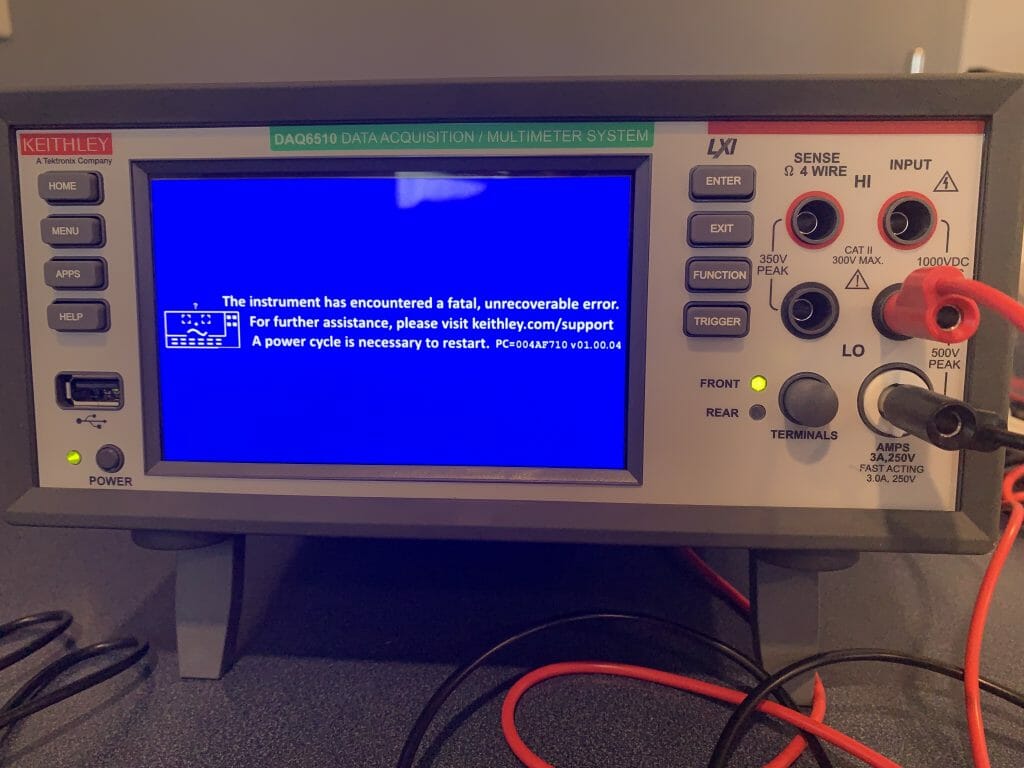
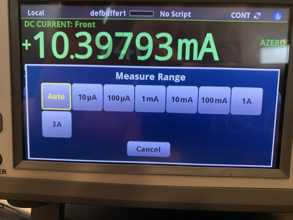
The one things that took me a LONG time to figure out is that I was having problems with the PSoC 6 resetting. My multimeter has a bunch of different ranges for current measurement. Each of these different ranges have a different shunt-resistor to increase the accuracy of the meter. The interesting part is that the meter actually uses a mechanical relay to switch between the ranges. You can hear it clicking between the ranges. It turns out that sometime the relay switching took long enough that the PSoC6 would loose power and reset.
Measure the Sleep Time?
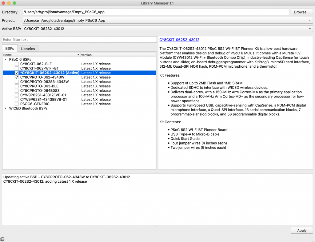
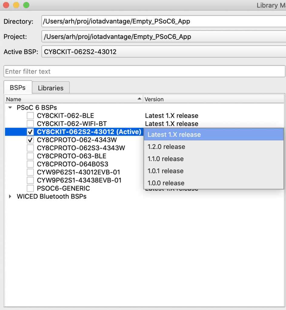
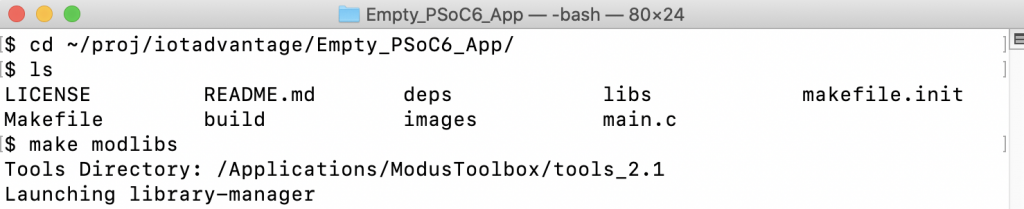
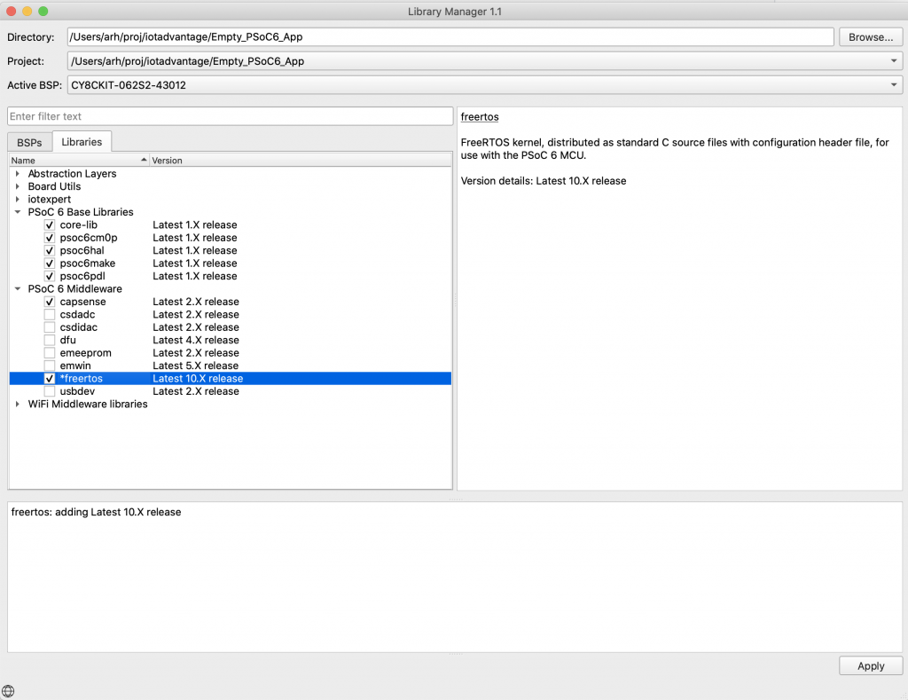
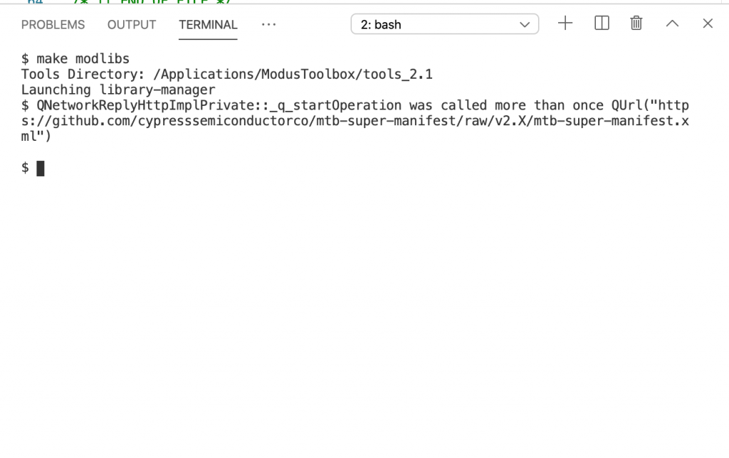
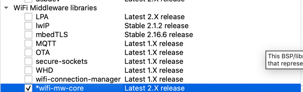
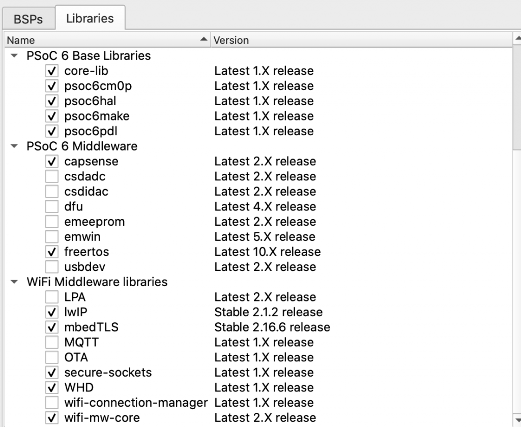
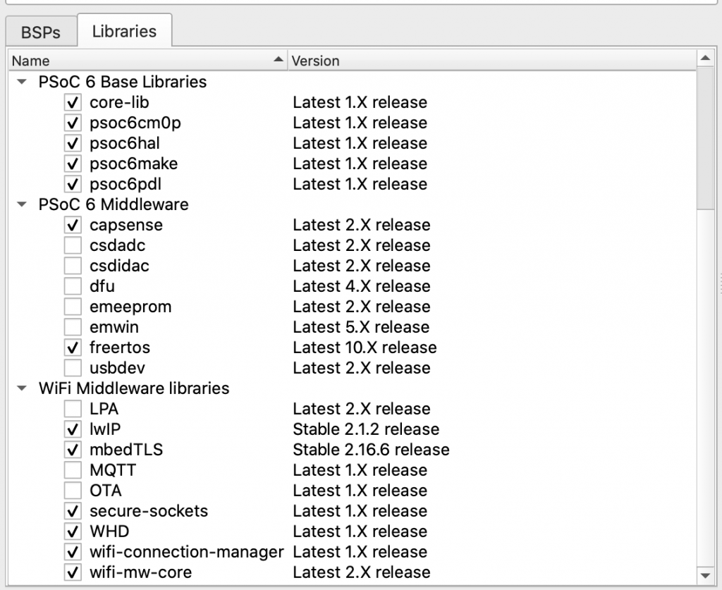
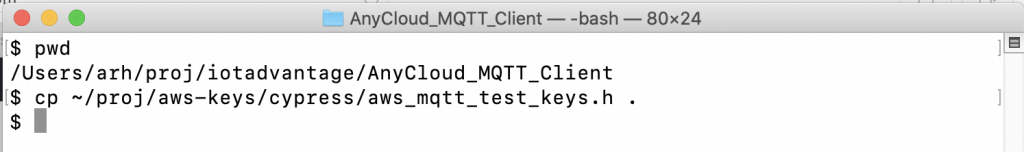
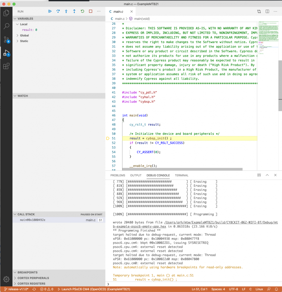
The next thing that I was curious about was how long it actually slept. So I created a new project which would print out the counter values before and after the sleeps using printf which was added to my project with “Retarget I/O”. You can do this in the library manager.
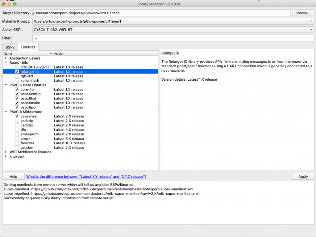
Once the library is added to your project you can enable it by adding the
#include "cy_retarget_io.h"
And
cy_retarget_io_init(CYBSP_DEBUG_UART_TX, CYBSP_DEBUG_UART_RX, CY_RETARGET_IO_BAUDRATE);
In this project I add prints to look at the sleep time… on lines 42 & 48
#include "cy_pdl.h"
#include "cyhal.h"
#include "cybsp.h"
#include "cy_retarget_io.h"
cyhal_lptimer_t myTimer;
#define MSDELAY 2000
static inline uint32_t msToTicks(uint32_t ms)
{
return (uint32_t)(CY_SYSCLK_WCO_FREQ*(ms/1000));
}
int main(void)
{
uint32_t sleepTime=0,wakeTime=0,totalTime=0;
cybsp_init() ;
cy_retarget_io_init(CYBSP_DEBUG_UART_TX, CYBSP_DEBUG_UART_RX, CY_RETARGET_IO_BAUDRATE);
printf("Started Project\n");
cyhal_gpio_init(CYBSP_LED8,CYHAL_GPIO_DIR_OUTPUT,CYHAL_GPIO_DRIVE_STRONG,1);
cyhal_gpio_init(CYBSP_LED9,CYHAL_GPIO_DIR_OUTPUT,CYHAL_GPIO_DRIVE_STRONG,1);
cyhal_lptimer_init(&myTimer);
cyhal_lptimer_enable_event (&myTimer, CYHAL_LPTIMER_COMPARE_MATCH, 4, true);
__enable_irq();
for(;;)
{
cyhal_lptimer_set_delay(&myTimer,msToTicks(MSDELAY));
cyhal_gpio_write(CYBSP_LED8,0); cyhal_gpio_write(CYBSP_LED9,1);
sleepTime = cyhal_lptimer_read(&myTimer);
cyhal_system_deepsleep();
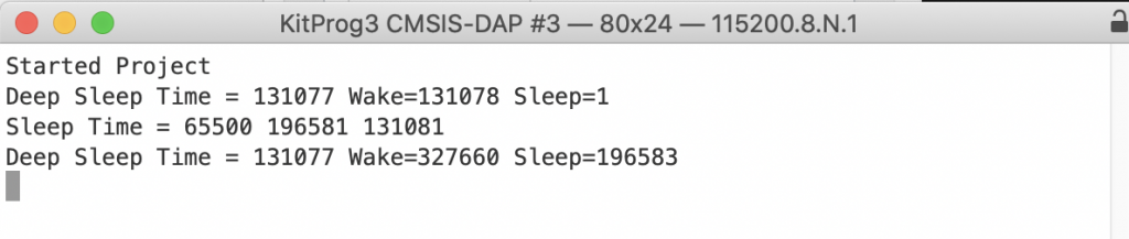
wakeTime = cyhal_lptimer_read(&myTimer);
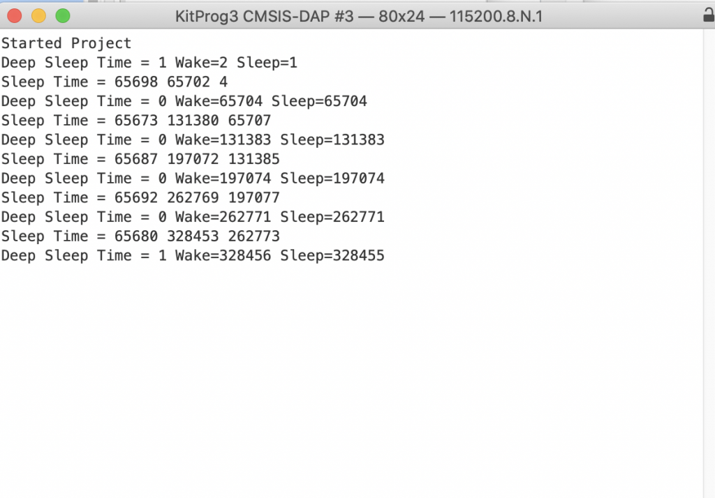
printf("Deep Sleep Time = %ld Wake=%ld Sleep=%ld\n",wakeTime-sleepTime,wakeTime,sleepTime);
cyhal_gpio_write(CYBSP_LED8,1); cyhal_gpio_write(CYBSP_LED9,0);
sleepTime = cyhal_lptimer_read(&myTimer);
Cy_SysLib_Delay(MSDELAY);
wakeTime = cyhal_lptimer_read(&myTimer);
totalTime = (wakeTime<sleepTime)?wakeTime+UINT32_MAX-sleepTime:wakeTime-sleepTime;
printf("Sleep Time = %ld %ld %ld\n",totalTime,wakeTime,sleepTime);
}
}
I immediately see that something is wrong. Now my project never DeepSleeps. But why?
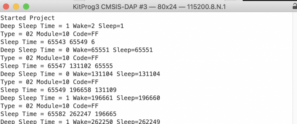
In order to figure this out I add the code to look at the return code from the cyhal_deep_sleep function.
		cy_rslt_t failedCode = cyhal_system_deepsleep();
		wakeTime = cyhal_lptimer_read(&myTimer);
		printf("Deep Sleep Time = %ld Wake=%ld Sleep=%ld\n",wakeTime-sleepTime,wakeTime,sleepTime);
		uint8_t type = CY_RSLT_GET_TYPE(failedCode);
		uint16_t module_id = CY_RSLT_GET_MODULE(failedCode);
		uint16_t error_code = CY_RSLT_GET_CODE(failedCode);
		printf("Type = %02X Module=%02X Code=%02X\n",type,module_id,error_code);
When I run this you see that I am getting error code 0xFF. But where is that coming from?
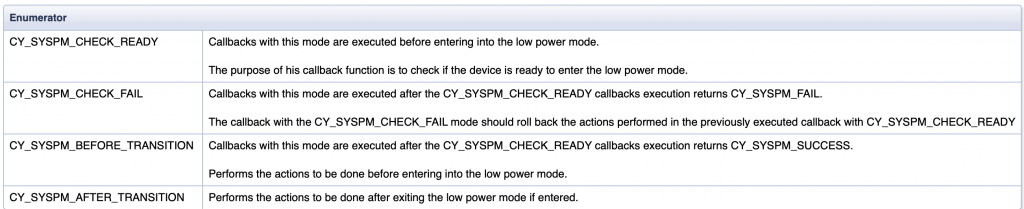
Now is a good time to examine the lower power callbacks. When you initialize the UART in the HAL it will add a low power callback. The low power call back is called in one of four situations:
When you look a the hal uart initialization function in cy
cy_rslt_t cyhal_uart_init(cyhal_uart_t *obj, cyhal_gpio_t tx, cyhal_gpio_t rx, const cyhal_clock_divider_t *clk, const cyhal_uart_cfg_t *cfg)
{
    CY_ASSERT(NULL != obj);
On line 278 it sets up the callback function “cyhal_uart_pm_callback”
        obj->pm_params.base = obj->base;
        obj->pm_params.context = obj;
        obj->pm_callback.callback = &cyhal_uart_pm_callback;
        obj->pm_callback.type = CY_SYSPM_DEEPSLEEP;
        obj->pm_callback.skipMode = 0;
        obj->pm_callback.callbackParams = &(obj->pm_params);
        obj->pm_callback.prevItm = NULL;
        obj->pm_callback.nextItm = NULL;
        if (!Cy_SysPm_RegisterCallback(&(obj->pm_callback)))
            result = CYHAL_UART_RSLT_ERR_PM_CALLBACK;
Then when you look in cy_hal_uart.c you see that the function will call the function Cy_SCB_UART_DeepSleepCallback (line 103)
static cy_en_syspm_status_t cyhal_uart_pm_callback(cy_stc_syspm_callback_params_t *params, cy_en_syspm_callback_mode_t mode)
{
    cyhal_uart_t *obj = params->context;
    cy_stc_syspm_callback_params_t pdl_params = { .base = obj->base, .context = &(obj->context) };
    cy_en_syspm_status_t rslt = Cy_SCB_UART_DeepSleepCallback(&pdl_params, mode);
    GPIO_PRT_Type *txport = obj->pin_tx != NC ? CYHAL_GET_PORTADDR(obj->pin_tx) : NULL,
                  *rtsport = obj->pin_rts != NC ? CYHAL_GET_PORTADDR(obj->pin_rts) : NULL;
    uint8_t txpin = (uint8_t)CYHAL_GET_PIN(obj->pin_tx), rtspin = (uint8_t)CYHAL_GET_PIN(obj->pin_rts);
    switch (mode)
    {
        case CY_SYSPM_CHECK_READY:
            if (rslt == CY_SYSPM_SUCCESS)
            {
                if (NULL != txport)
                {
                    obj->saved_tx_hsiom = Cy_GPIO_GetHSIOM(txport, txpin);
                    Cy_GPIO_Set(txport, txpin);
                    Cy_GPIO_SetHSIOM(txport, txpin, HSIOM_SEL_GPIO);
                }
                if (NULL != rtsport)
                {
                    obj->saved_rts_hsiom = Cy_GPIO_GetHSIOM(rtsport, rtspin);
                    Cy_GPIO_Set(rtsport, rtspin);
                    Cy_GPIO_SetHSIOM(rtsport, rtspin, HSIOM_SEL_GPIO);
                }
            }
            break;

        case CY_SYSPM_CHECK_FAIL: // fallthrough
        case CY_SYSPM_AFTER_TRANSITION:
            if (NULL != txport)
            {
                Cy_GPIO_SetHSIOM(txport, txpin, obj->saved_tx_hsiom);
            }
            if (NULL != rtsport)
            {
                Cy_GPIO_SetHSIOM(rtsport, rtspin, obj->saved_rts_hsiom);
            }
            break;

        default:
            break;
    }
    return rslt;
}
And in the PDL file cy_scb_uart.c you can see that this function will fail if there is data currently being transmitted (line 315)
cy_en_syspm_status_t Cy_SCB_UART_DeepSleepCallback(cy_stc_syspm_callback_params_t *callbackParams, cy_en_syspm_callback_mode_t mode)
{
    cy_en_syspm_status_t retStatus = CY_SYSPM_FAIL;

    CySCB_Type *locBase = (CySCB_Type *) callbackParams->base;
    cy_stc_scb_uart_context_t *locContext = (cy_stc_scb_uart_context_t *) callbackParams->context;

    switch(mode)
    {
        case CY_SYSPM_CHECK_READY:
        {
            /* Check whether the High-level API is not busy executing the transmit
            * or receive operation.
            */
            if ((0UL == (CY_SCB_UART_TRANSMIT_ACTIVE & Cy_SCB_UART_GetTransmitStatus(locBase, locContext))) &&
                (0UL == (CY_SCB_UART_RECEIVE_ACTIVE  & Cy_SCB_UART_GetReceiveStatus (locBase, locContext))))
            {
                /* If all data elements are transmitted from the TX FIFO and
                * shifter and the RX FIFO is empty: the UART is ready to enter
                * Deep Sleep mode.
                */
                if (Cy_SCB_UART_IsTxComplete(locBase))
                {
                    if (0UL == Cy_SCB_UART_GetNumInRxFifo(locBase))
                    {
                        /* Disable the UART. The transmitter stops driving the
                        * lines and the receiver stops receiving data until
                        * the UART is enabled.
                        * This happens when the device failed to enter Deep
                        * Sleep or it is awaken from Deep Sleep mode.
                        */
                        Cy_SCB_UART_Disable(locBase, locContext);

                        retStatus = CY_SYSPM_SUCCESS;
                    }
                }
            }
        }
        break;

        case CY_SYSPM_CHECK_FAIL:
        {
            /* The other driver is not ready for Deep Sleep mode. Restore the
            * Active mode configuration.
            */

            /* Enable the UART to operate */
            Cy_SCB_UART_Enable(locBase);

            retStatus = CY_SYSPM_SUCCESS;
        }
        break;

        case CY_SYSPM_BEFORE_TRANSITION:
            /* Do noting: the UART is not capable of waking up from
            * Deep Sleep mode.
            */
        break;

        case CY_SYSPM_AFTER_TRANSITION:
        {
            /* Enable the UART to operate */
            Cy_SCB_UART_Enable(locBase);

            retStatus = CY_SYSPM_SUCCESS;
        }
        break;

        default:
            break;
    }

    return (retStatus);
}
But, where does the error code come from? When you click on it, you find yourself on this enumeration:
typedef enum
{
    CY_SYSPM_SUCCESS         = 0x0U,                                         /**< Successful. */
    CY_SYSPM_BAD_PARAM       = CY_SYSPM_ID | CY_PDL_STATUS_ERROR | 0x01U,    /**< One or more invalid parameters. */
    CY_SYSPM_TIMEOUT         = CY_SYSPM_ID | CY_PDL_STATUS_ERROR | 0x02U,    /**< A time-out occurred. */
    CY_SYSPM_INVALID_STATE   = CY_SYSPM_ID | CY_PDL_STATUS_ERROR | 0x03U,    /**< The operation is not setup or is in an
                                                                                  improper state. */
    CY_SYSPM_CANCELED        = CY_SYSPM_ID | CY_PDL_STATUS_ERROR | 0x04U,    /**< Operation canceled. */
    CY_SYSPM_SYSCALL_PENDING = CY_SYSPM_ID | CY_PDL_STATUS_ERROR | 0x05U,    /**< Canceled due syscall operation pending. */
    CY_SYSPM_FAIL            = CY_SYSPM_ID | CY_PDL_STATUS_ERROR | 0xFFU     /**< Unknown failure. */
} cy_en_syspm_status_t;
And when you look at CY_SYSPM_ID your find:
/** SysPm driver identifier */
#define CY_SYSPM_ID                      (CY_PDL_DRV_ID(0x10U))
OK… so the reason in our project that it doesn’t go into deep sleep is that the printf from earlier has not finished. To fix this you update your project to keep trying until the DeepSleep call succeeds (on lines 43-45)
	for(;;)
	{
		cyhal_lptimer_set_delay(&myTimer,msToTicks(MSDELAY));
		cyhal_gpio_write(CYBSP_LED8,0);	cyhal_gpio_write(CYBSP_LED9,1);
		sleepTime = cyhal_lptimer_read(&myTimer);
		cy_rslt_t failedCode;
		do {
			failedCode = cyhal_system_deepsleep();
		} while(failedCode != CY_SYSPM_SUCCESS);

		wakeTime = cyhal_lptimer_read(&myTimer);

		printf("Deep Sleep Time = %ld Wake=%ld Sleep=%ld\n",wakeTime-sleepTime,wakeTime,sleepTime);


		cyhal_gpio_write(CYBSP_LED8,1);	cyhal_gpio_write(CYBSP_LED9,0);
		sleepTime = cyhal_lptimer_read(&myTimer);
		Cy_SysLib_Delay(MSDELAY);
		wakeTime = cyhal_lptimer_read(&myTimer);
 		totalTime = (wakeTime<sleepTime)?wakeTime+UINT32_MAX-sleepTime:wakeTime-sleepTime;
		printf("Sleep Time = %ld %ld %ld\n",totalTime,wakeTime,sleepTime);
	}
Now this makes a lot more sense