Summary
This article walks you through the first use of a Keithley 7700 20-channel multiplexer module attached to a Keithley DAQ6510.
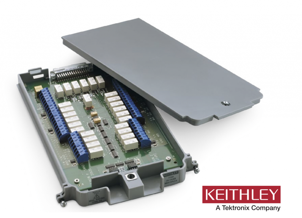
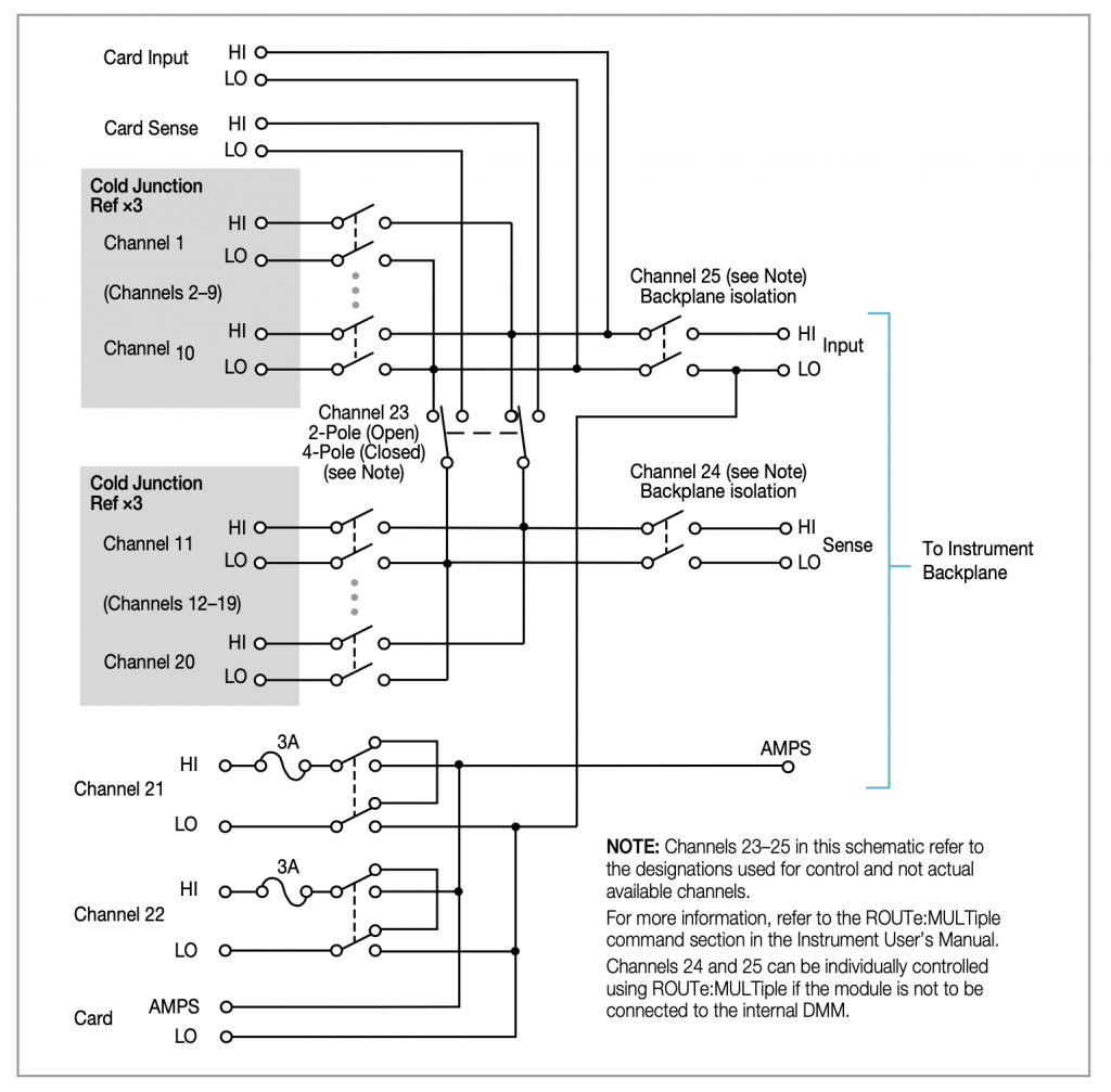
Keithley describes the module in the data sheet as “The 7700 plug-in module offers 20 channels of 2-pole or 10 channels of 4-pole multiplexer switching that can be configured as two independent banks of multiplexers. There are two additional protected channels for current measurements. Automatic CJC
is provided so that no other accessories are required to make thermocouple temperature measurements. In addition, the 7700 contains latching electromechanical relays that enable signal bandwidths of up to 50 MHz. The 7700 is ideal for RTD, thermistor, and thermocouple temperature applications.” And they give a nice picture:
And a “schematic”:
The Story
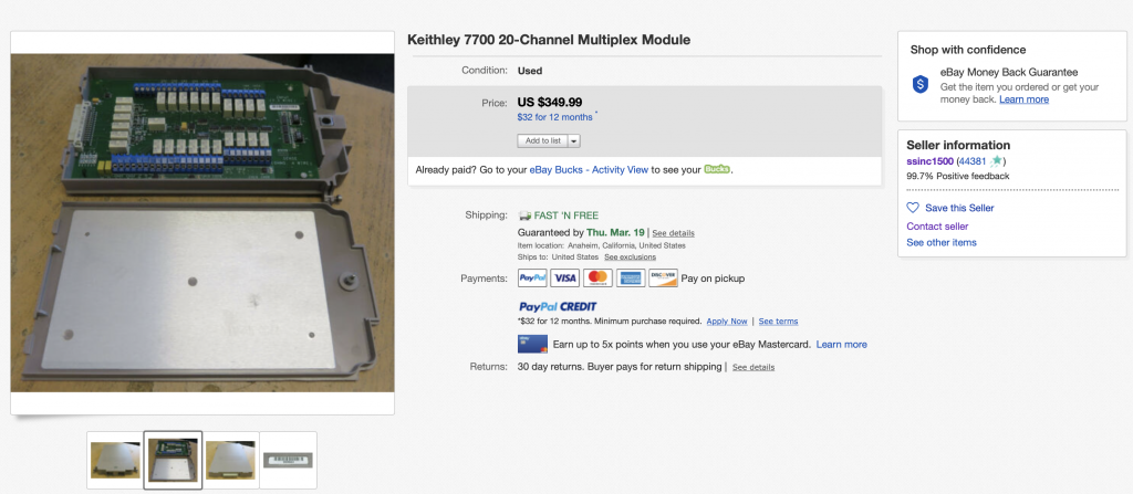
When I bought my original DAQ6510 from Mouser, they did not have a 7700 multiplexer module in stock. So, I decided to buy one on eBay, which I was really hoping would work. The module was salvaged out of some installation somewhere in California by a company called “Silicon Salvage” I was a little bit worried about it because the multiplexor uses actual mechanical relays which wear out in somewhere between 100K and 100M switches. That seemed like a lot, but who knows.
Assemble
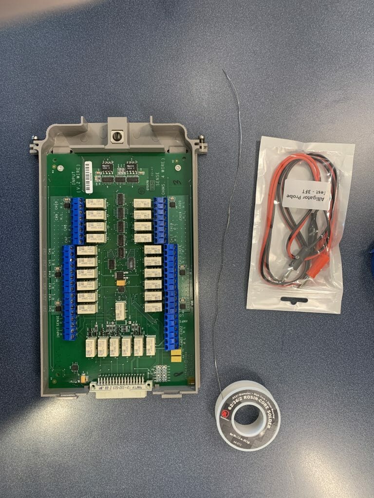
When the unit arrived it seemed OK. So I put my lab assistant to assembling and testing it. To test it I bought a bunch of really inexpensive alligator to banana plug wires from China.
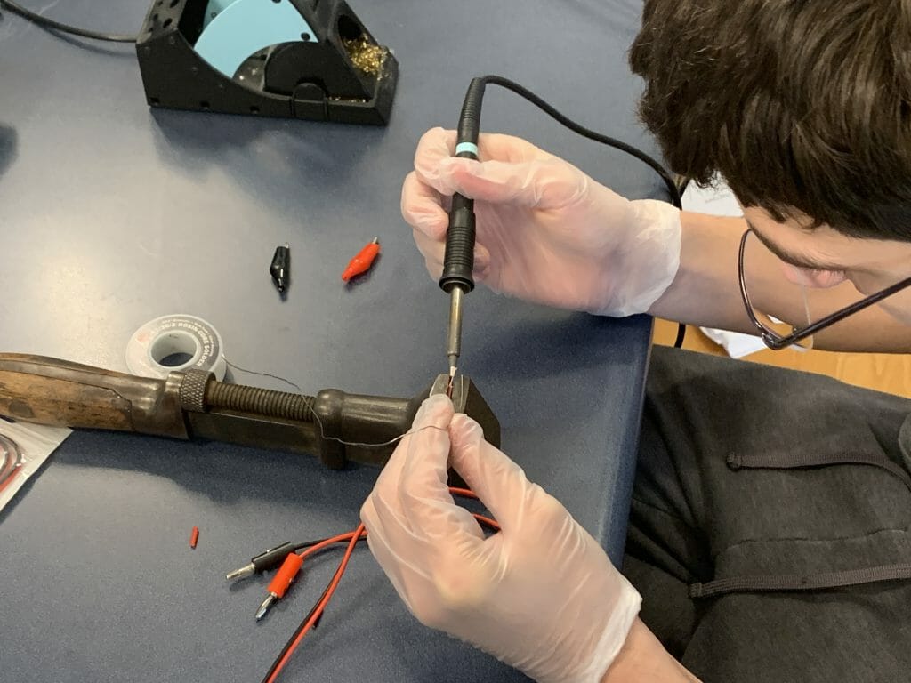
Then Nicholas clipped off the alligator ends and tinned the wires. How about that classic soldering vice? That was bought at an antique sale in Georgetown Kentucky a few years ago and works great for this kind of thing. It is also heavy enough to kill Zombies with.
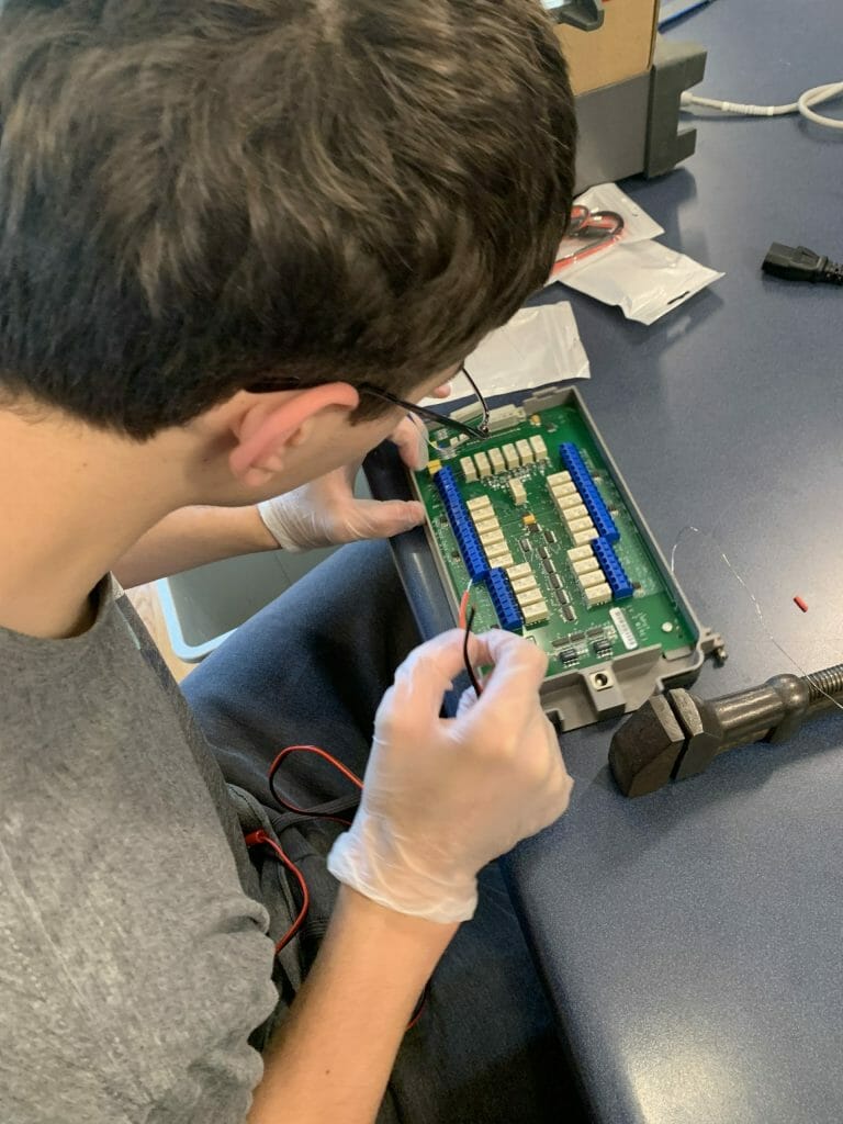
Then he installed the jumper wires onto the board.
Try it out
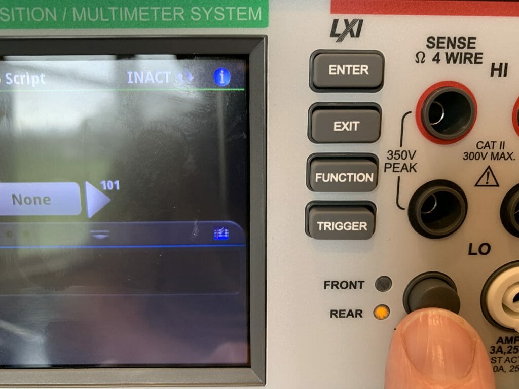
When everything was button up it was time to test. Start with turning on the meter and pressing the rear button.
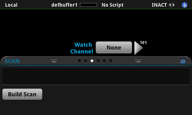
Then press “Build Scan”
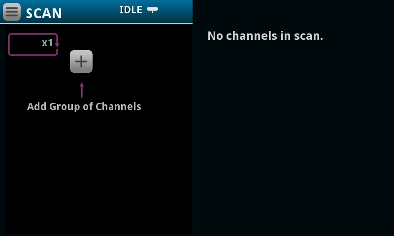
Press the “Plus” symbol (to create a new list of channel and settings) to scan
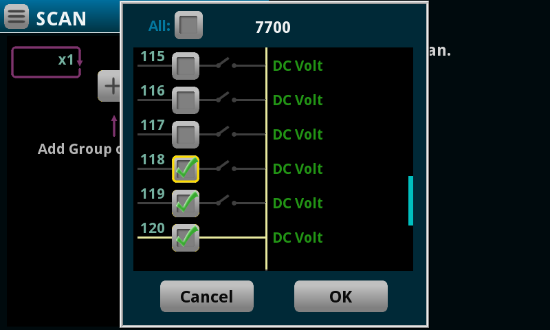
Select some channels and press OK. It turned out that we tested 3-wires at a time because I used a 3-channel power to supply to setup the voltages to test.
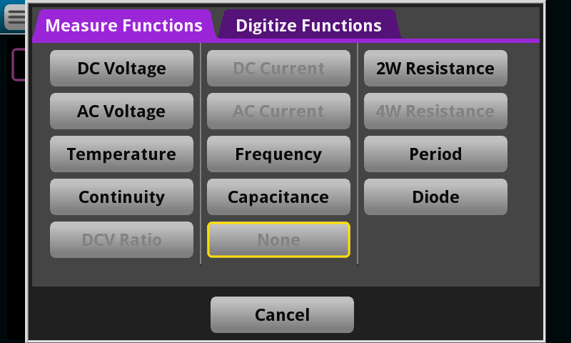
Then pick out DC Voltage
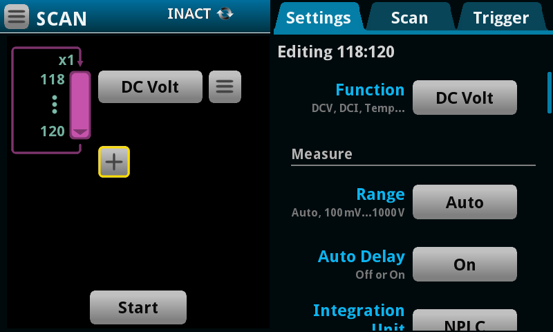
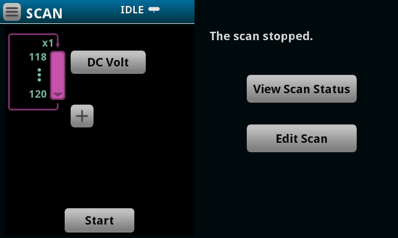
Press the Start Button to launch the meter to scan through the channels and save the values.
And the screen will look like this.
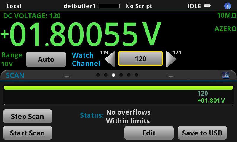
If you press the view scan status you will end on a screen like this. Notice that you can only see channel 120. To fix this press the “120”
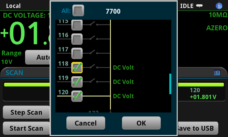
Then select the other two channels
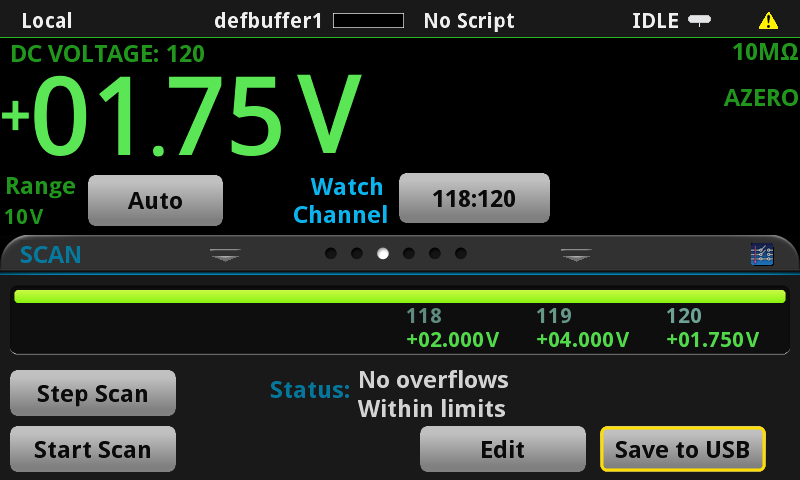
And you will now see all of the voltages
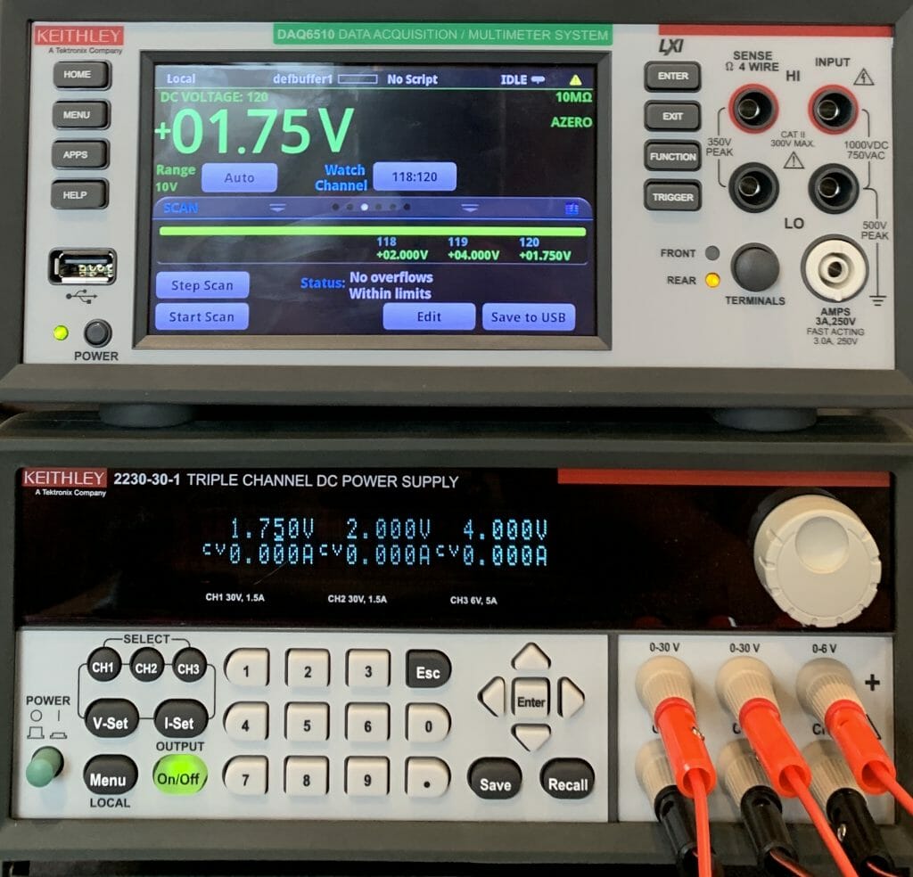
Here is a picture of the whole thing
Channel Grid App
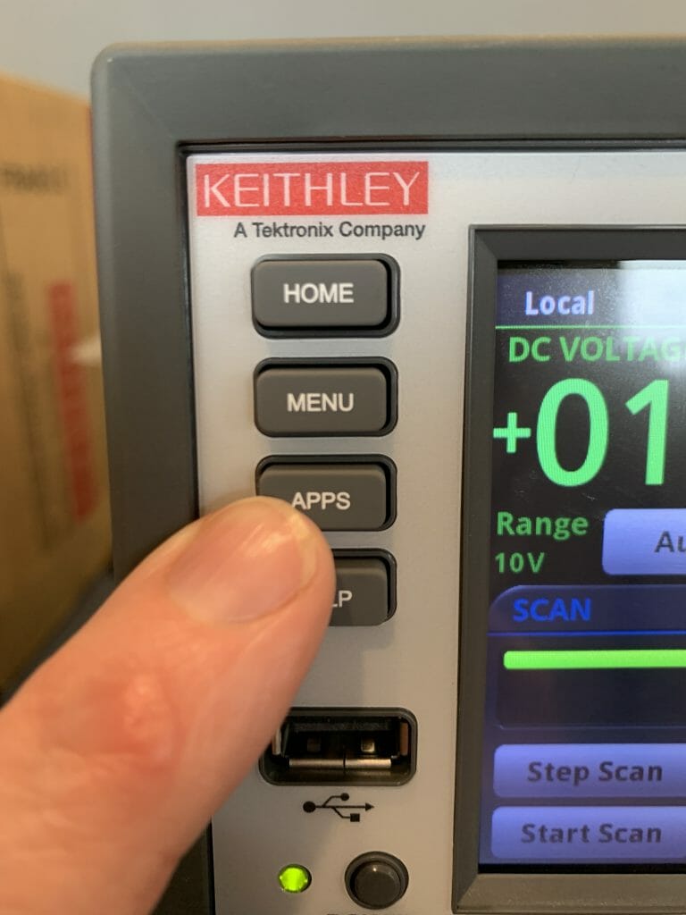
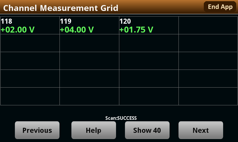
The DAQ also have a function to display a grid of the channel values. To get there Press the Apps button
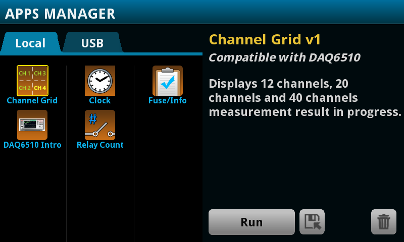
Press “Channel Grid” then Run
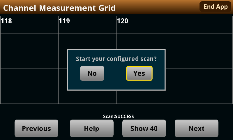
It will then ask you to start the Scan
And when it is done you will have the voltages.
It would be really nice if this App had button to re-scan. Or potentially a way to run the scans in a loop. I am pretty sure that they give you a way to create Apps to run on this meter… so I suppose I’ll need to fix their App.
Reading Table
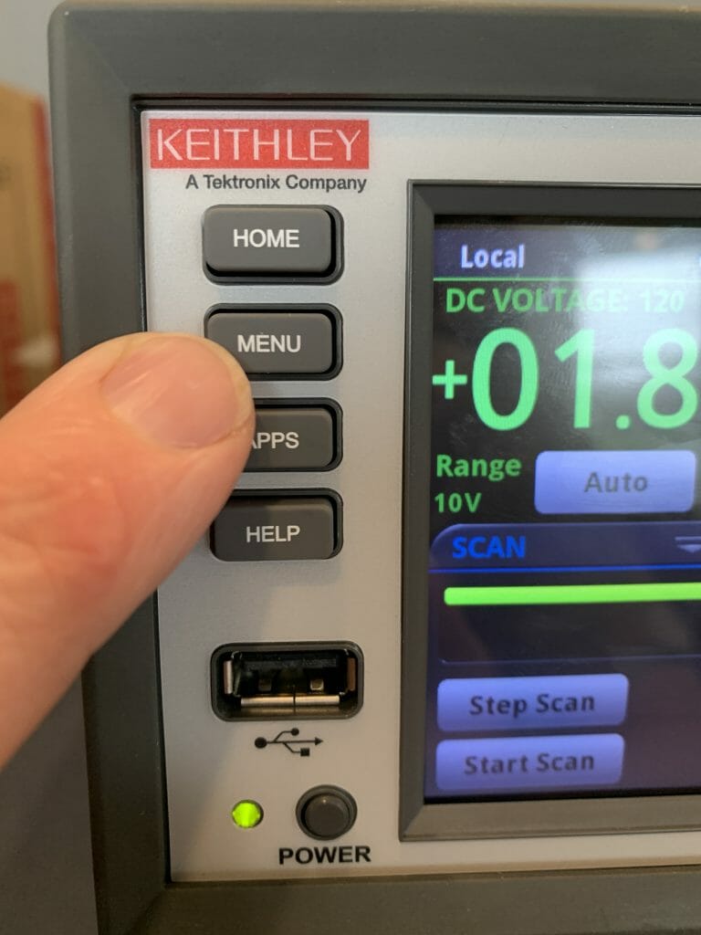
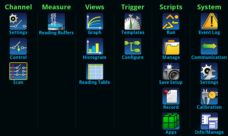
You can also view the scan data in a table. To do this, press “Menu”
Press the “Reading Table”
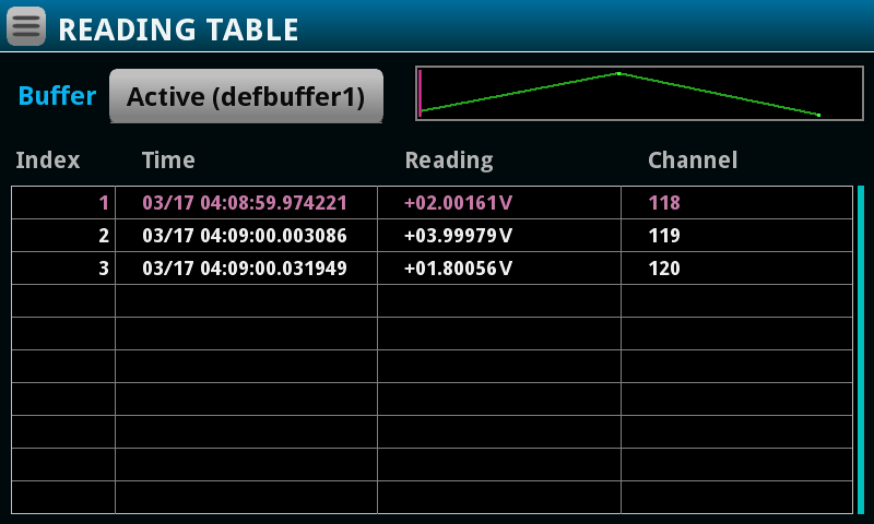
Which will take you to see a table of the previous scan values.
Step Scan
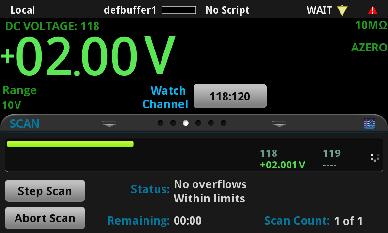
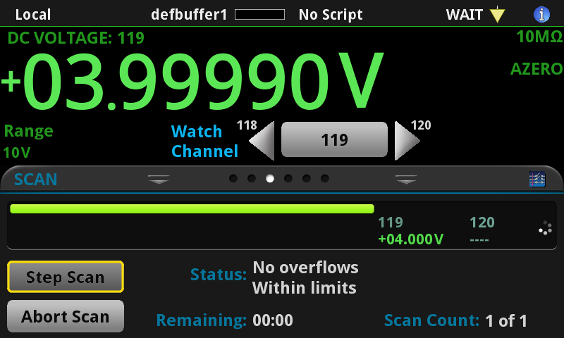
You can also manually scan the channels by running a “Step Scan”. Press the “Step Scan” button.
Which will read and display the first channel.
Then you can repeatedly click to work your way through all of the channels.

No comment yet, add your voice below!