Keithley DAQ6510 & 7700

Summary

This article walks you through the first use of a Keithley 7700 20-channel multiplexer module attached to a Keithley DAQ6510.

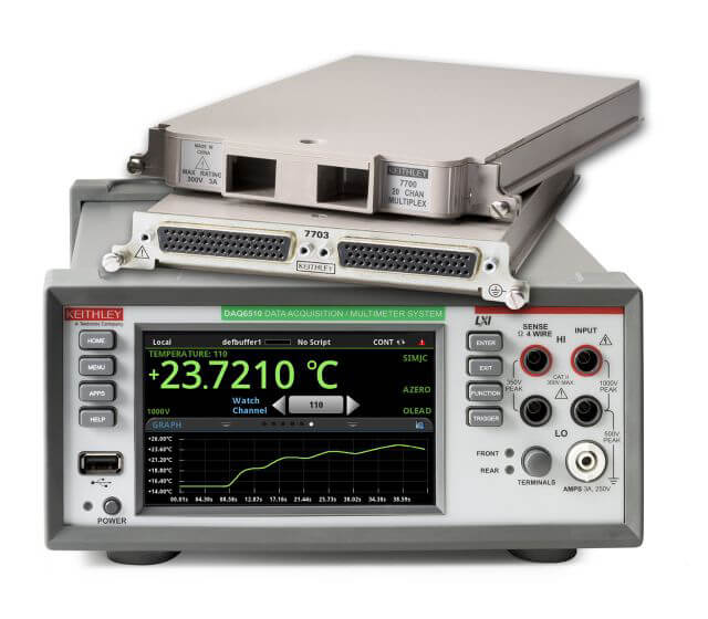
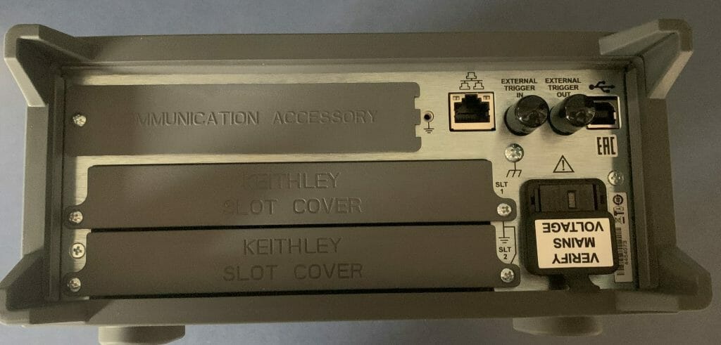
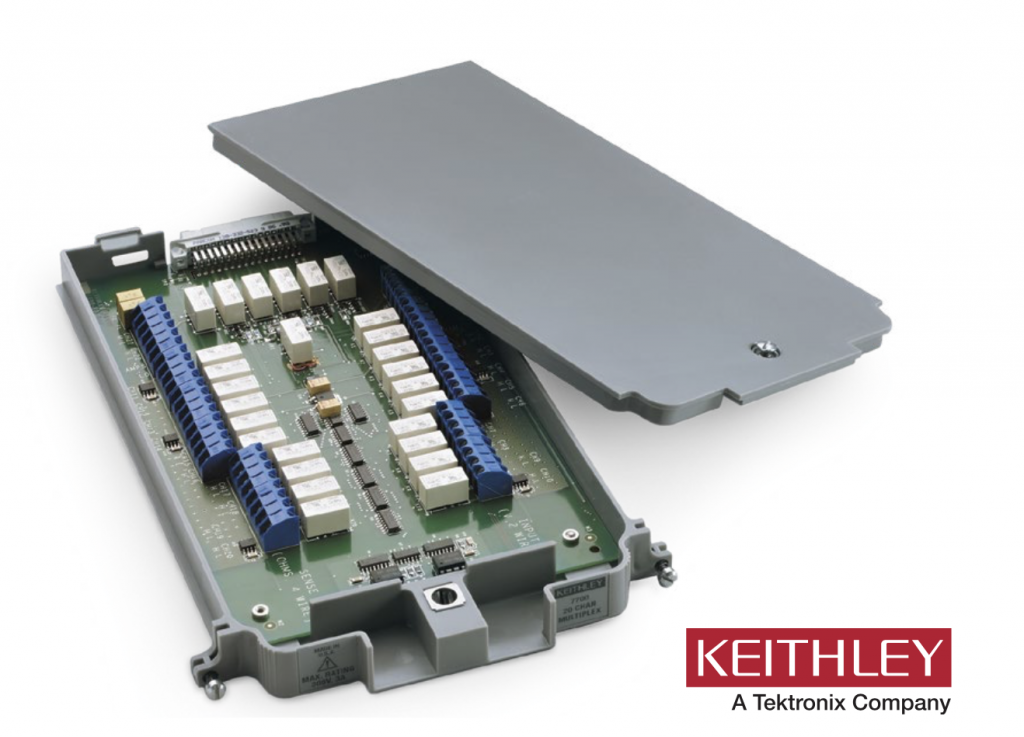
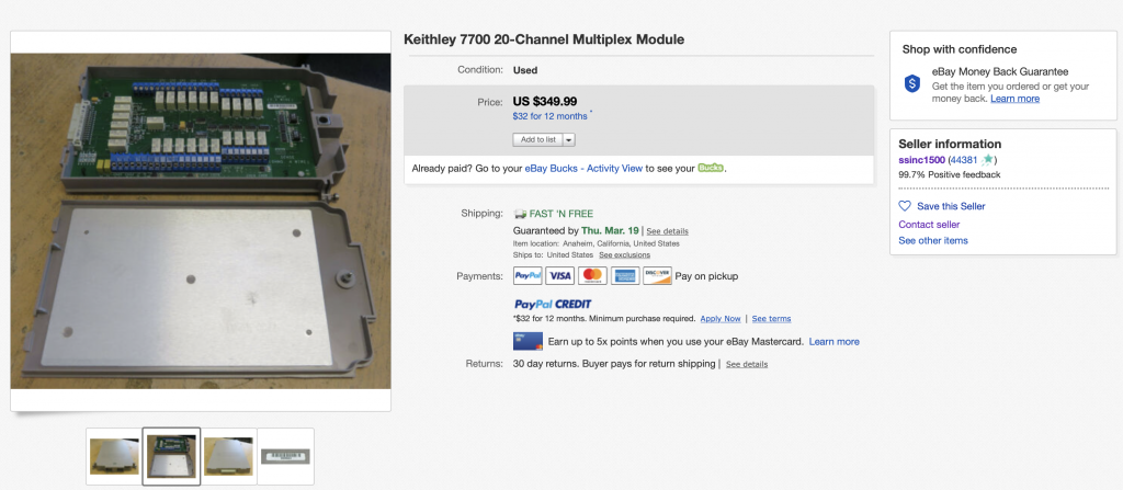
Keithley describes the module in the data sheet as “The 7700 plug-in module offers 20 channels of 2-pole or 10 channels of 4-pole multiplexer switching that can be configured as two independent banks of multiplexers. There are two additional protected channels for current measurements. Automatic CJC
is provided so that no other accessories are required to make thermocouple temperature measurements. In addition, the 7700 contains latching electromechanical relays that enable signal bandwidths of up to 50 MHz. The 7700 is ideal for RTD, thermistor, and thermocouple temperature applications.”  And they give a nice picture:
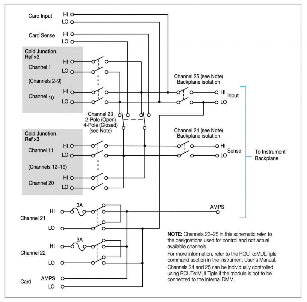
And a “schematic”:

The Story

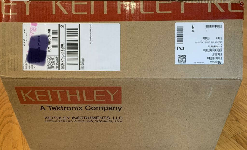
When I bought my original DAQ6510 from Mouser, they did not have a 7700 multiplexer module in stock.  So, I decided to buy one on eBay, which I was really hoping would work.  The module was salvaged out of some installation somewhere in California by a company called “Silicon Salvage”  I was a little bit worried about it because the multiplexor uses actual mechanical relays which wear out in somewhere between 100K and 100M switches.  That seemed like a lot, but who knows.

Assemble

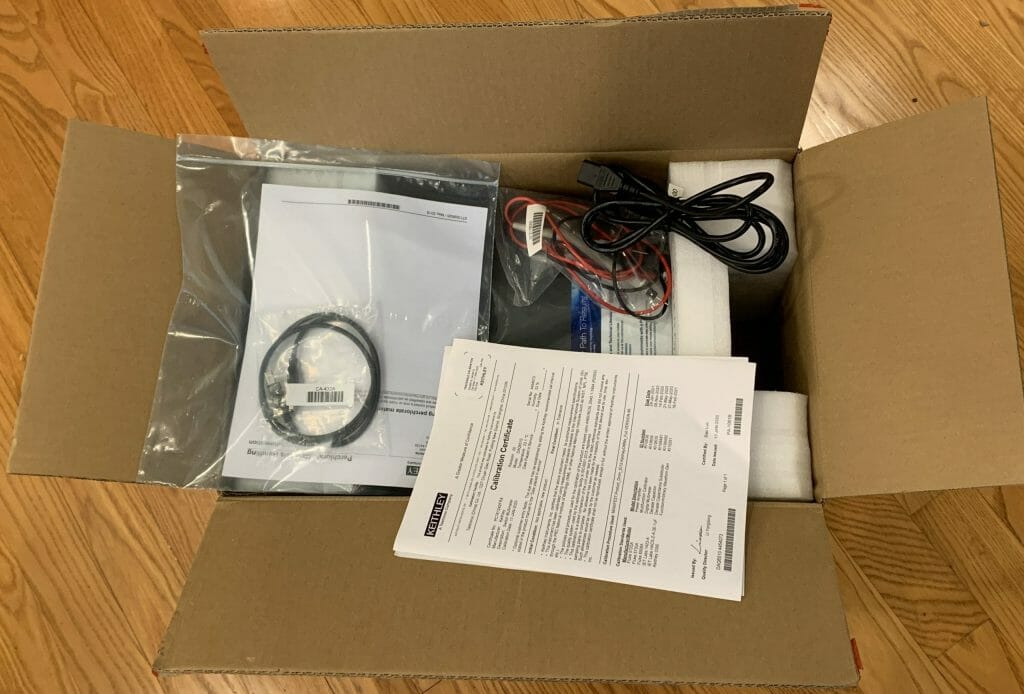
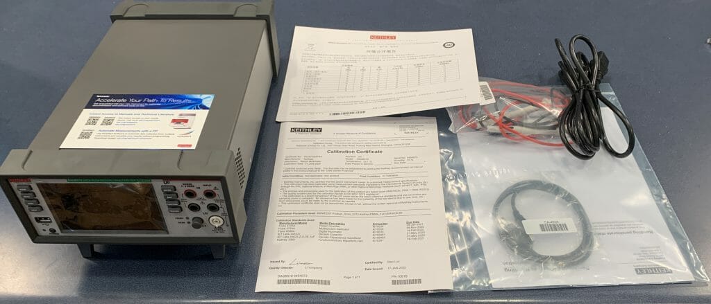
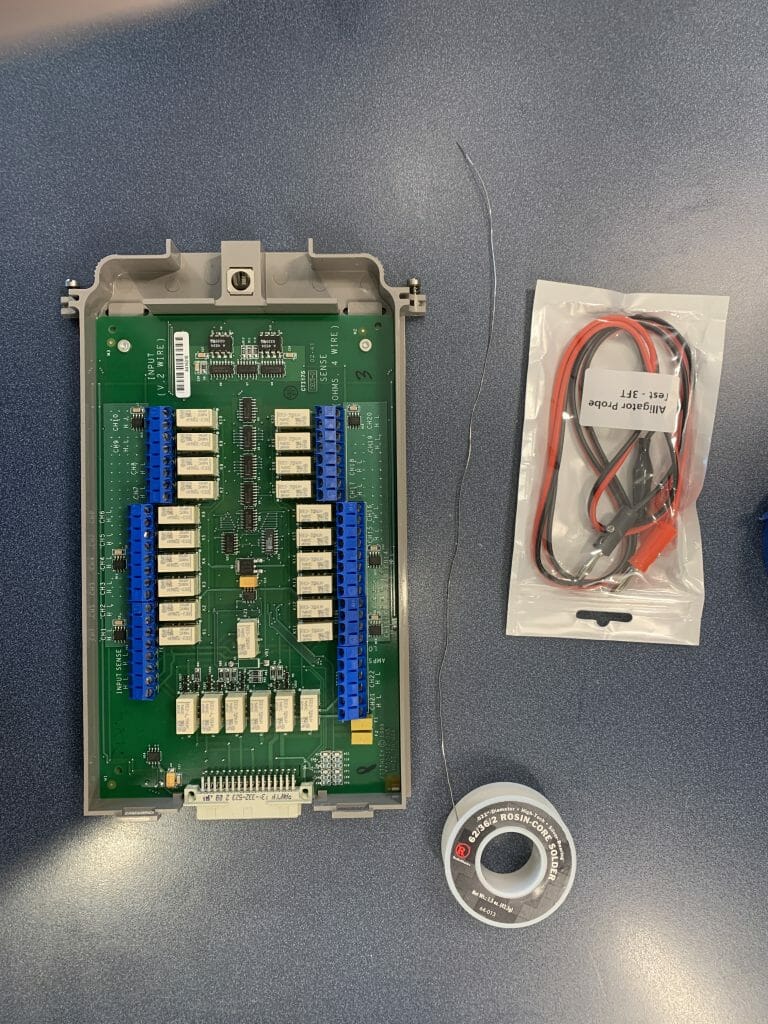
When the unit arrived it seemed OK.  So I put my lab assistant to assembling and testing it.  To test it I bought a bunch of really inexpensive alligator to banana plug wires from China.

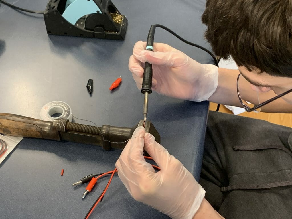
Then Nicholas clipped off the alligator ends and tinned the wires.  How about that classic soldering vice?  That was bought at an antique sale in Georgetown Kentucky a few years ago and works great for this kind of thing.  It is also heavy enough to kill Zombies with.

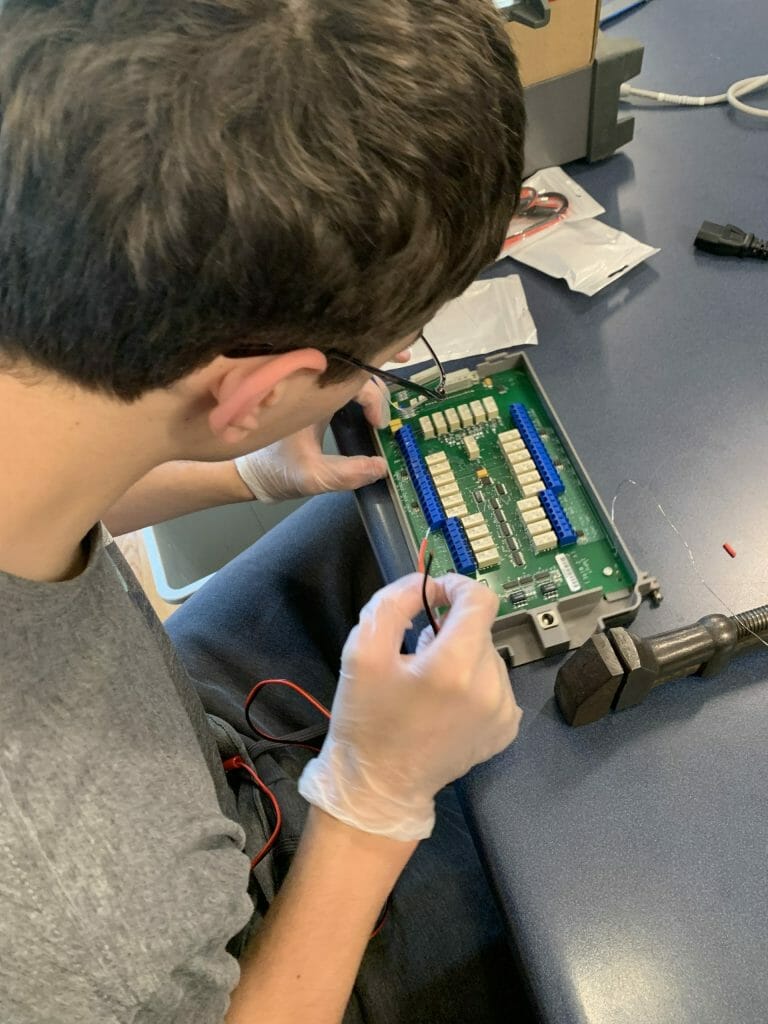
Then he installed the jumper wires onto the board.

Try it out

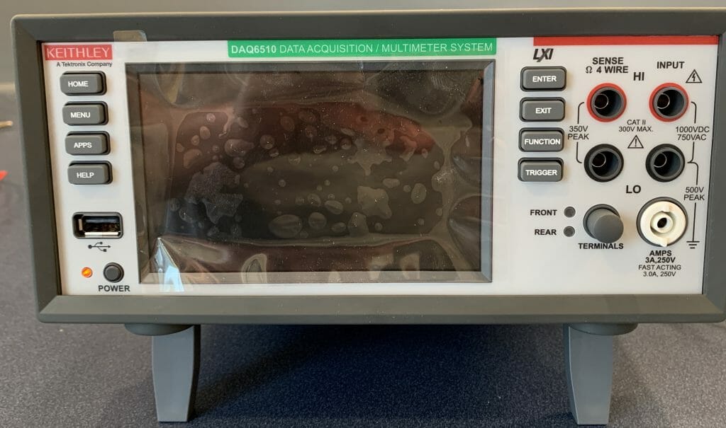
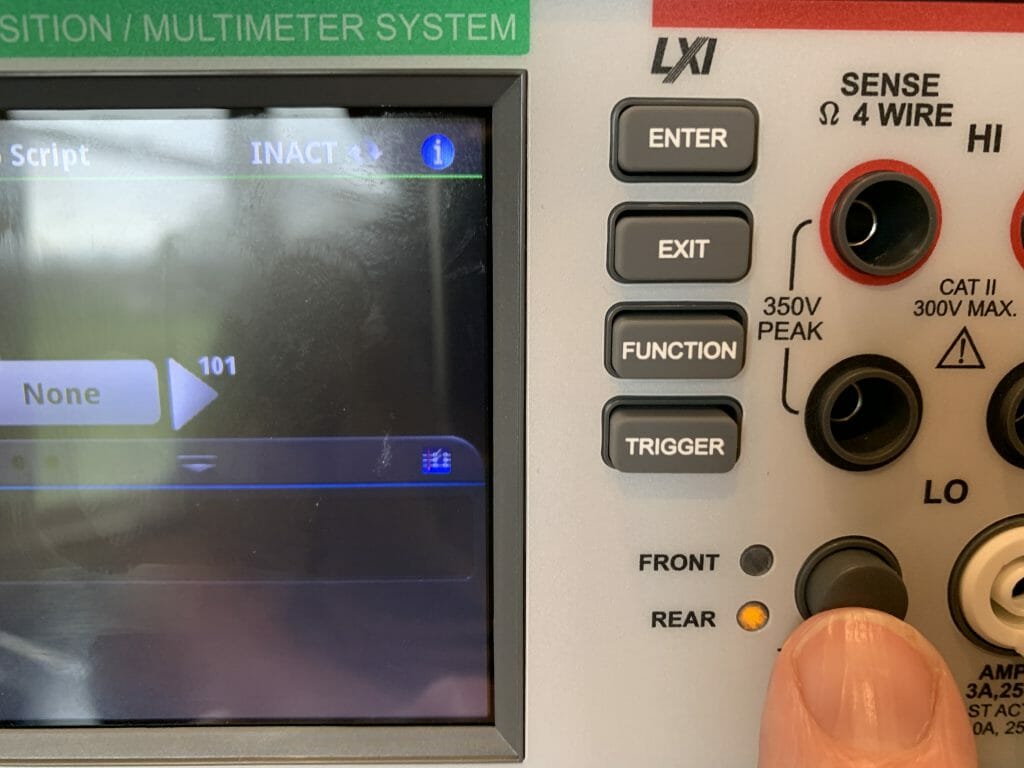
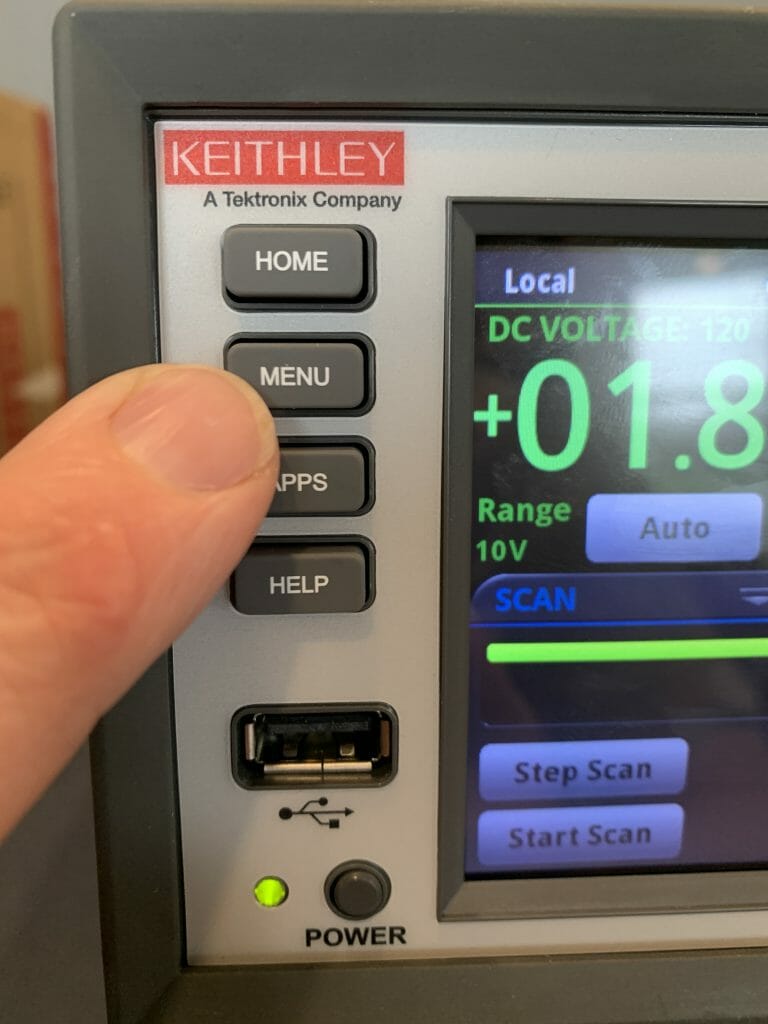
When everything was button up it was time to test.  Start with turning on the meter and pressing the rear button.

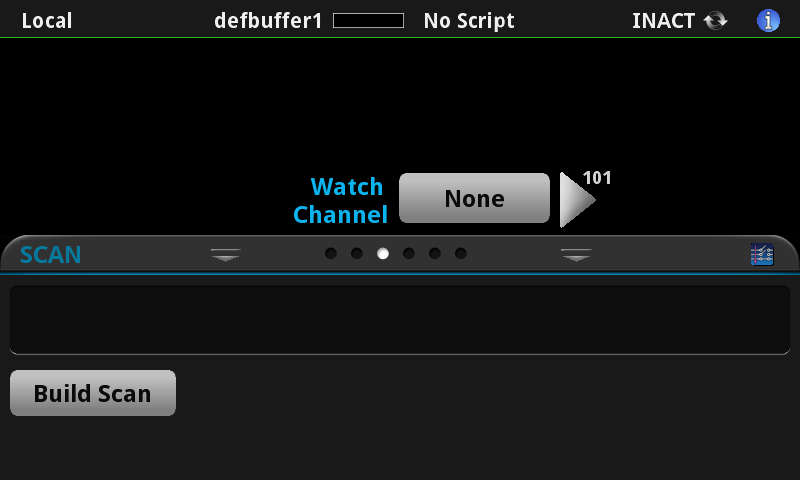
Then press “Build Scan”

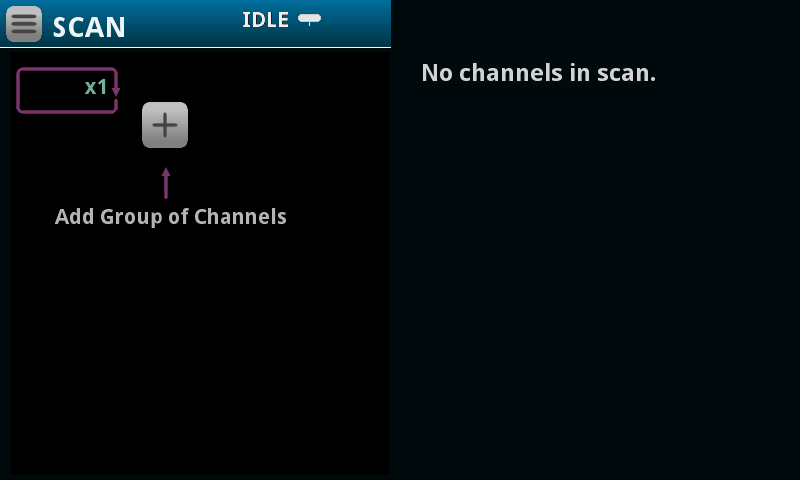
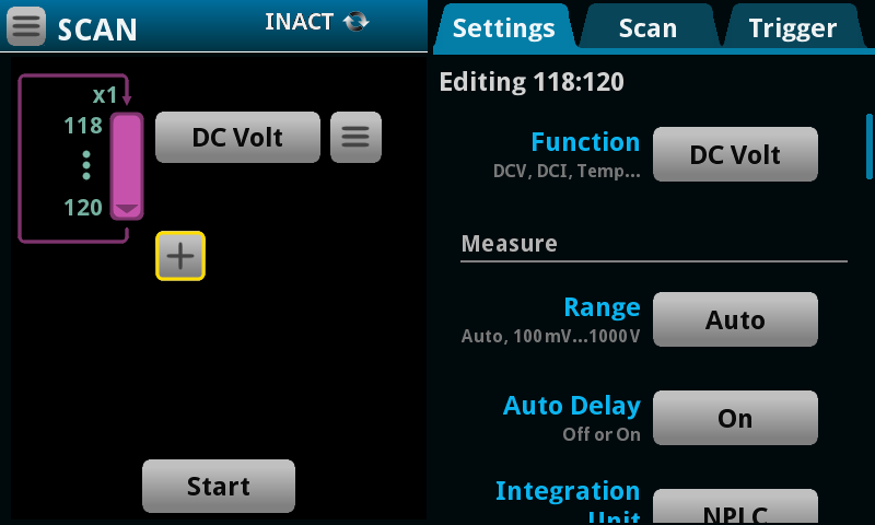
Press the “Plus” symbol (to create a new list of channel and settings) to scan

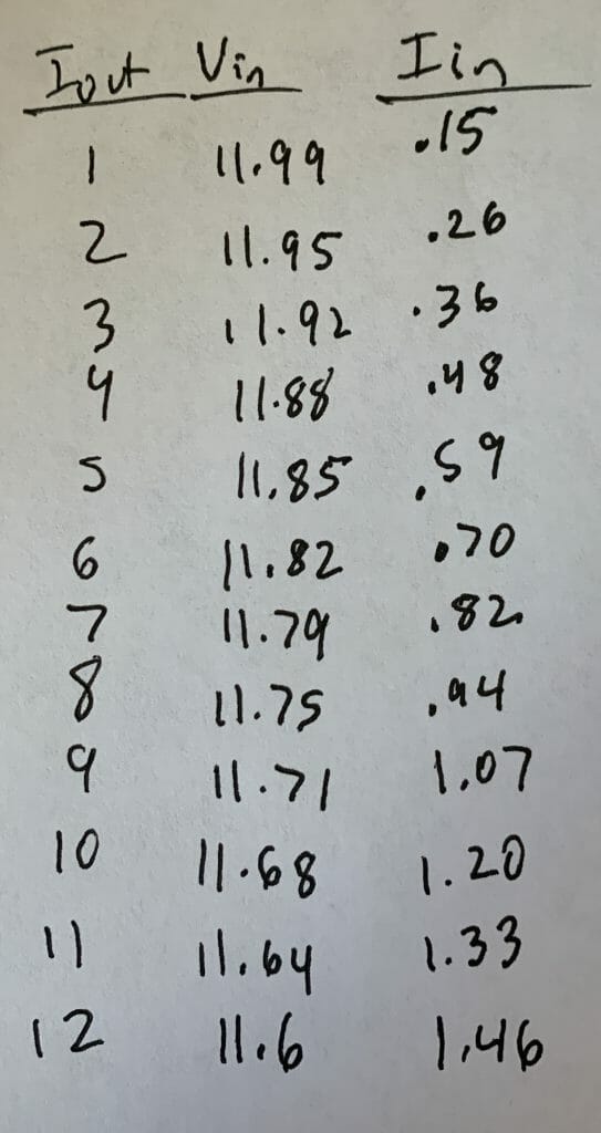
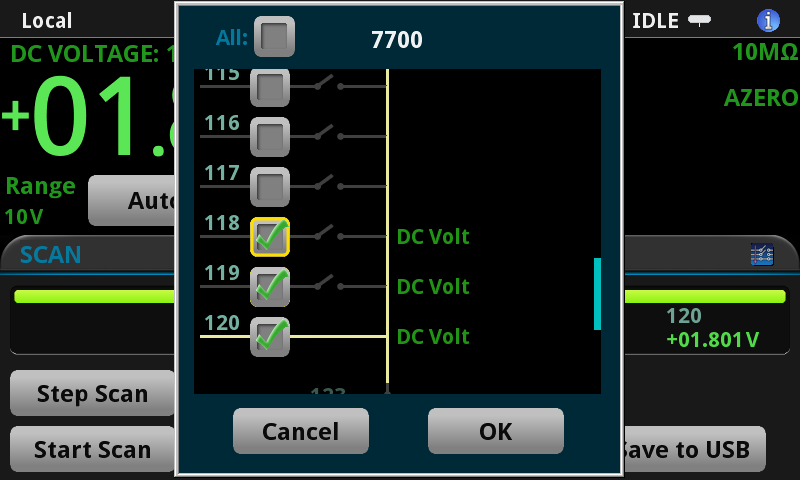
Select some channels and press OK.  It turned out that we tested 3-wires at a time because I used a 3-channel power to supply to setup the voltages to test.

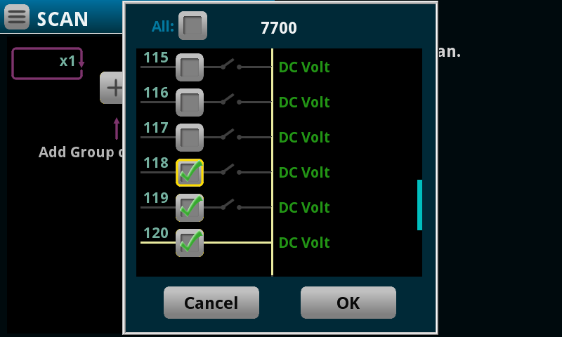
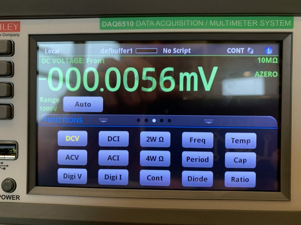
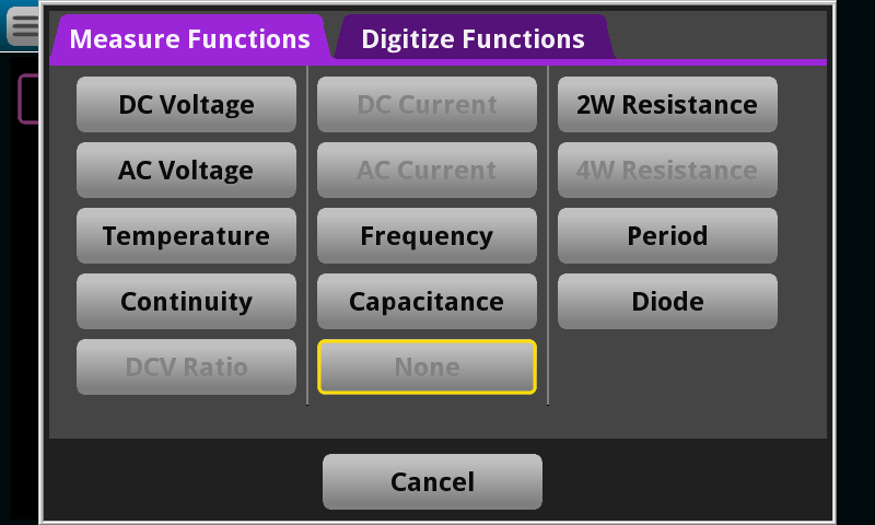
Then pick out DC Voltage

Press the Start Button to launch the meter to scan through the channels and save the values.

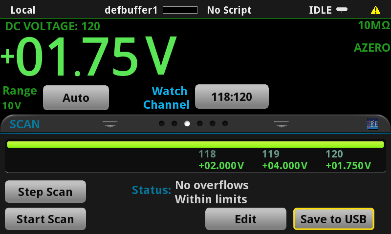
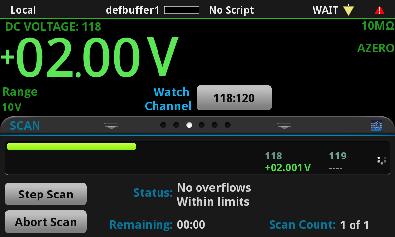
And the screen will look like this.

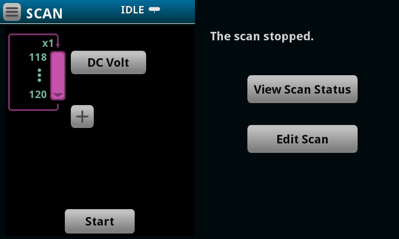
If you press the view scan status you will end on a screen like this.  Notice that you can only see channel 120.  To fix this press the “120”

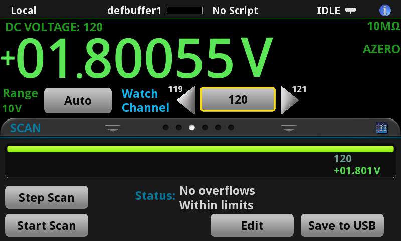
Then select the other two channels

And you will now see all of the voltages

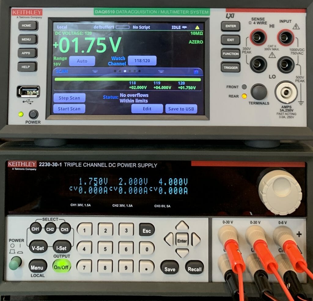
Here is a picture of the whole thing

Channel Grid App

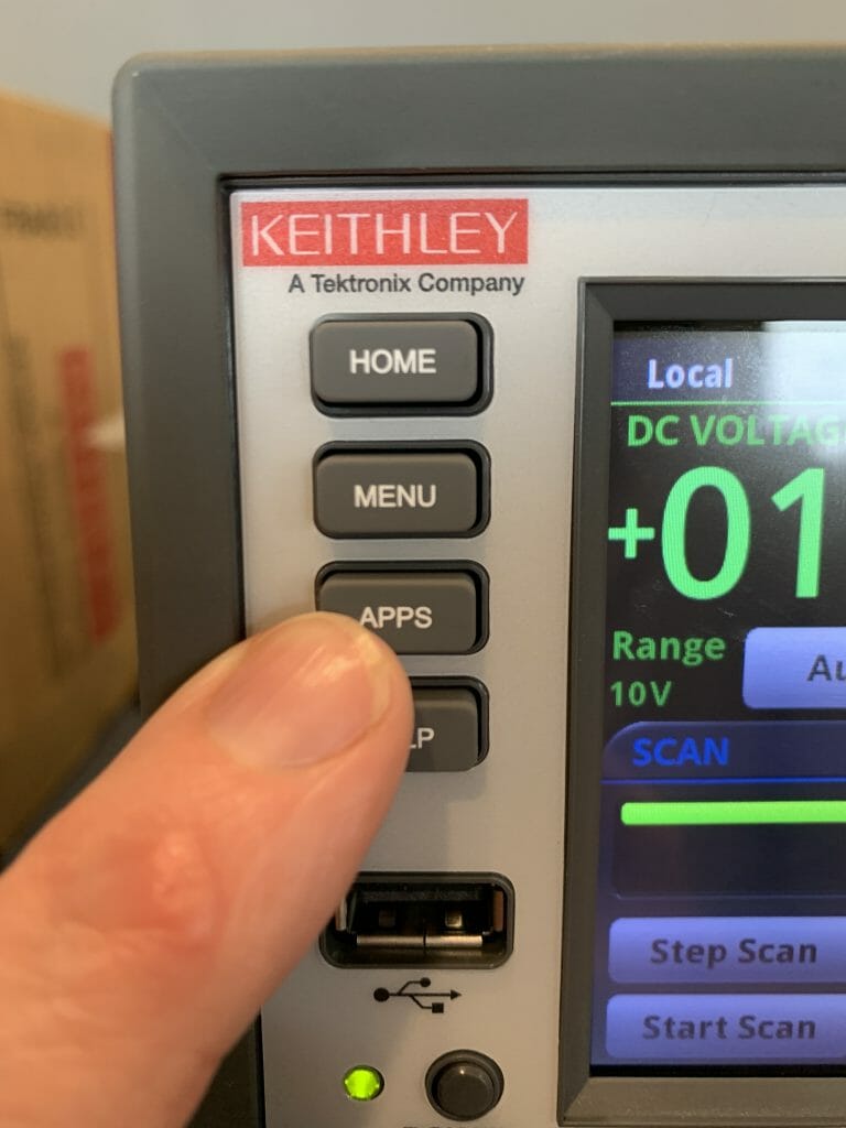
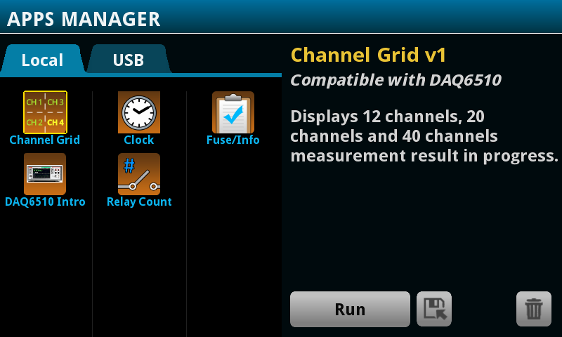
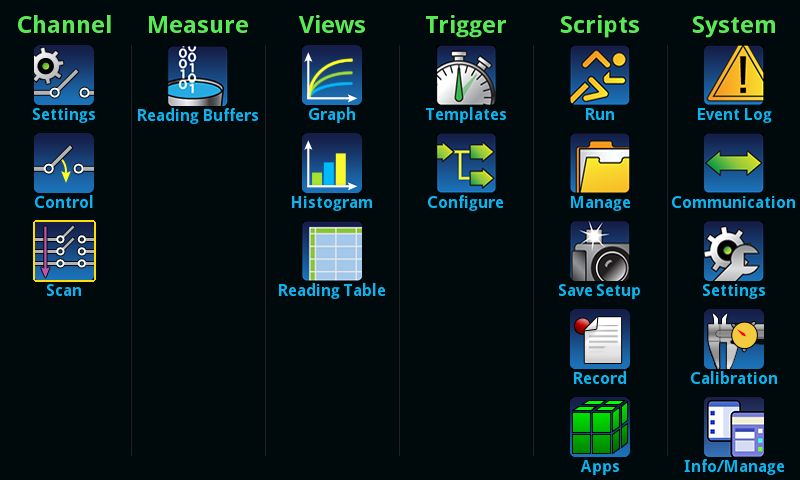
The DAQ also have a function to display a grid of the channel values.  To get there Press the Apps button

Press “Channel Grid” then Run

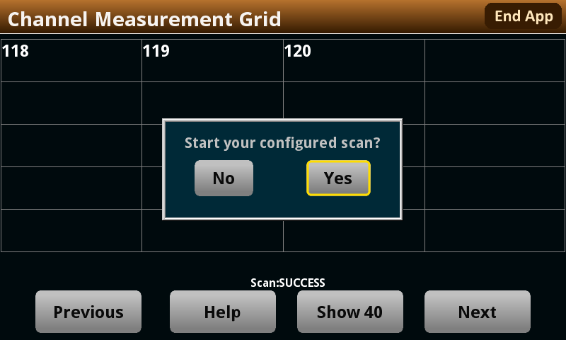
It will then ask you to start the Scan

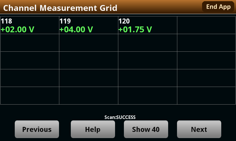
And when it is done you will have the voltages.

It would be really nice if this App had button to re-scan.  Or potentially a way to run the scans in a loop.  I am pretty sure that they give you a way to create Apps to run on this meter… so I suppose I’ll need to fix their App.

Reading Table

You can also view the scan data in a table.  To do this, press “Menu”

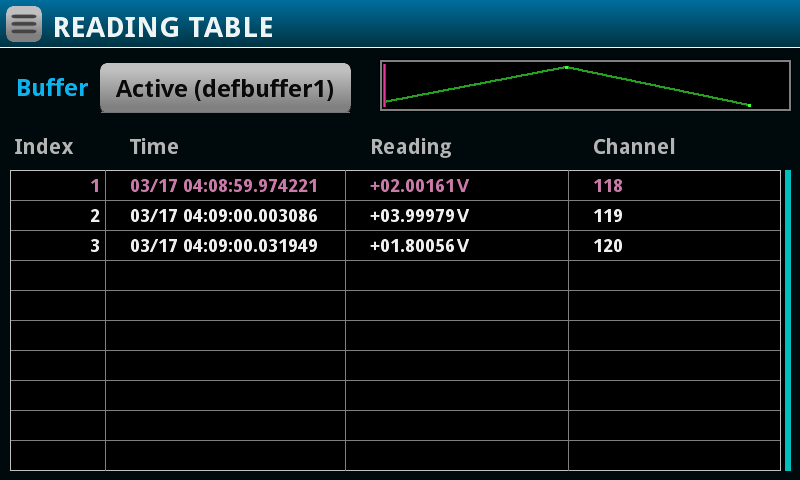
Press the “Reading Table”

Which will take you to see a table of the previous scan values.

Step Scan

You can also manually scan the channels by running a “Step Scan”.  Press the “Step Scan” button.

Which will read and display the first channel.

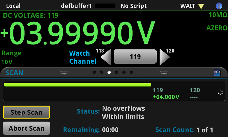
Then you can repeatedly click to work your way through all of the channels.

Keithley DAQ6510 Unboxing

Summary

A bunch of pictures of the unboxing of my new Keithley DAQ6510.  DAQ stands for Data Acquisition.  This box is essentially a 6.5 digit multimeter with a 20+ channel multiplexor attached.

The Story

My lab assistant, Nicholas, says that Unboxing is big in social media and that I really need to do an unboxing for IoT Expert.  Well here it is.  As I am sure you know, I have been working on a power supply design for a new IoT device.  As part of this I needed the ability to measure voltage and current from several different places and my trusty Fluke wasn’t going to be able to do that.

I bought this from my good friends at Mouser.  Here is the box.

When you open it here is what you see.

If I take everything out there is

  1. The meter
  2. Some test leads
  3. The manual
  4. a USB cable
  5. And a calibration certificate

On the back there is two places to plug in multiplexers + a LXI ethernet connection, power, USB, two BNC triggers, and a communication port.

It is always fun to tear off the film over the screen.

On the top there is a label with QR codes to documentation and software

When I turn it on, the system boots…

And then drops into DC voltage measurements.  Good new is that it measures 0

Unfortunately I very quickly ended up with the Blue Screen of Death (BSOD).

So I downloaded and installed the latest firmware (and it now seems to be stable).

When I turned on the current measurement with a PSoC 6 (in LP Active Mode)… I get numbers that make sense.


And this is cool… when I side swipe the screen it get a graph of the last 5ish minutes.


Cypress Type-C Barrel Connector Replacement + Infineon Buck DC/DC (Part 3)

Summary

This article walks you through the steps to test the CY4533 Type-C BCR & IR3894 under the load conditions from 1A to 12A.  In the previous article, I supplied power to the IR3894 using a bench top power supply.  For this set of experiments I will use a Type-C wall wart connected to the Cypress 4533 BCR development kit to supply power.

Test the BCR

The first thing that I do is connect the whole mess together like this:

Here is how it looks on my desk.  Note that the Keithey can measure current and voltage… but that I don’t have a way in this setup to measure either the voltage/current from the power supply or the current out of the CY4533

I step the output load from 1A to 12A in 1A increments.  I am super happy to see that the output voltage of the IR3894 is perfectly regulated to 1.198V.  It is also interesting to see that the Type-C power supply is able to keep the voltage within 3.25% of nominal even when I am using 12A on the IRDC3894 output (probably around 1.5A from the Type-C)

Measure the Input Current

In the previous article I used the current measurement from the Keithley bench top power supply.  In the setup above I don’t have a way to measure the actual input current.  To fix this put my new Keithley DAQ6510 in series with the IRDC3894 board.  Like this:

Then I step through the 1A-12A load conditions.  Once again the IR3894 provide a very well regulated voltage and current (exactly the same as before so I didn’t write them down)

Here is a table with the data from the previous post (without the Type-C power supply) versus the Type-C power supply.

2230-30-1 Power Supply With 6510 current meter in input path
Vin Iin Win Vout Iout Wout Eff Vin Iin Win Eff-C Loss
12 0.27 3.24 1.198 0 0 0%
12 0.129 1.548 1.198 0.998 1.195604 77% 11.91 0.129 1.53639 77.8% -0.6%
12 0.239 2.868 1.198 1.998 2.393604 83% 11.8 0.242 2.8556 83.8% -0.4%
12 0.345 4.14 1.198 2.998 3.591604 87% 11.7 0.352 4.1184 87.2% -0.5%
12 0.454 5.448 1.198 3.998 4.789604 88% 11.59 0.467 5.41253 88.5% -0.6%
12 0.564 6.768 1.198 4.999 5.988802 88% 11.47 0.586 6.72142 89.1% -0.6%
12 0.677 8.124 1.198 5.998 7.185604 88% 11.36 0.709 8.05424 89.2% -0.8%
12 0.792 9.504 1.198 6.998 8.383604 88% 11.25 0.837 9.41625 89.0% -0.8%
12 0.909 10.908 1.198 7.998 9.581604 88% 11.13 0.97 10.7961 88.8% -0.9%
12 1.029 12.348 1.198 8.998 10.779604 87% 10.95 1.115 12.20925 88.3% -1.0%
12 1.152 13.824 1.198 9.999 11.978802 87% 10.85 1.258 13.6493 87.8% -1.1%
12 1.277 15.324 1.198 10.998 13.175604 86% 10.8 1.401 15.1308 87.1% -1.1%
12 1.406 16.872 1.198 11.997 14.372406 85% 10.68 1.558 16.63944 86.4% -1.2%

These measurements use 1A/3A range on the Keithley DAQ6510 DMM, which means that they have a 100mΩ shunt resistor in series which drops the voltage by V=IR or about 0.1-ish volts.  This explains most of the difference from the Power Supply to the Type-C setup.

It is actually very interesting to look at the data to see the impact of lowering the input voltage on the efficiency of the IR3894.  It appears that at the highest load and lowest input voltage the efficiency is down by 1.2%

Watch the Sunrise

While I was sitting there at my desk thinking about what to do next, I decided that the best thing to do was go sit in my hottub and watch the sunrise on God’s country.

USB C Power Meter Tester

I was hoping to be able to measure the input current and voltage from the Type-C power supply so that I could calculate the efficiency of the CY4533 EZ BCR.  And as a result the efficiency of the whole system.  There wasn’t a place on the Type-C development kit to make these measurements, but the Cypress Apps manager for Type-C – Palani – said I should buy something like this from Amazon.


So I did.  You can plug it into Type-A or Type-C and it will tell you how much V/I are coming out.  In the picture below you can see 20.4v@0.11A

Even better it has a handy-dandy mode where it can display Chinese?

Here is a picture in my actual setup:

And a picture of the whole crazy setup.

Now I step through my 12 load conditions from 1A to 12A and record the V/I from the Fluke and the USB Power Tester.

Here is the data in table form with power and efficiency added.

Type C Power Tester
Vin Iin Win Eff-No Meter
11.99 0.15 1.7985 66.5%
11.95 0.26 3.107 77.0%
11.92 0.36 4.2912 83.7%
11.88 0.48 5.7024 84.0%
11.85 0.59 6.9915 85.7%
11.82 0.7 8.274 86.8%
11.79 0.82 9.6678 86.7%
11.75 0.94 11.045 86.8%
11.71 1.07 12.5297 86.0%
11.68 1.2 14.016 85.5%
11.64 1.33 15.4812 85.1%
11.6 1.46 16.936 84.9%

Next, I plot the new data with the previous two plots.  Obviously, it is screwed up.  I would bet money that the data points at 2A, 4A and 12A are wrong.  But, I don’t think that it is worthwhile to take steps to figure out the real current.  So, I suppose that is what you get from a $19 power meter.

Efficiency of CY4533 EZ-PD BCR

I had really wanted to measure the efficiency of the BCR setup.  To do that I needed to be able to measure the output power (V/I) and the input power (V/I).  Unfortunately the power meter doesn’t seem to be very good… so I suppose that I will have to wait to build my real board where I can install some power jumpers the real numbers.