Summary
I have been working on a bunch of PSoC 6 projects in preparation for some new videos and for use at Embedded World. For one of those project I need a motion sensitive remote control… and conveniently enough we put a Bosch BMI160 motion sensor onto the new CY8CKIT-028-EPD shield that comes with the CY8CKIT-062-BLE development kit.
In this article I will show you how to make a complete test system using PSoC 6 to talk to the BMI160. The steps are:
- Clone the Bosch BMI160 Driver Library
- Create a new PSoC 6 project & add the driver library
- Create the HAL for the Bosch Driver
- Create the main firmware and test
Clone the Bosch BMI160 Driver Library
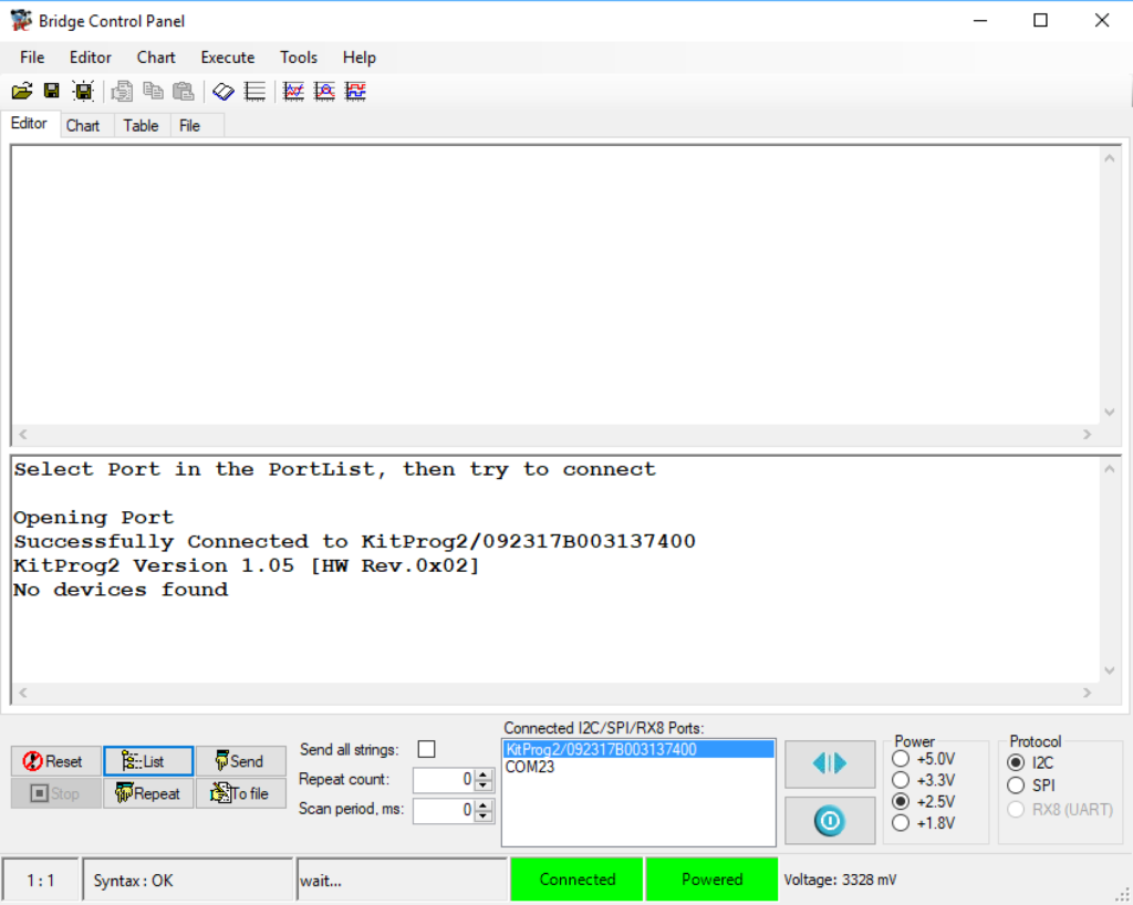
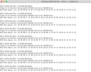
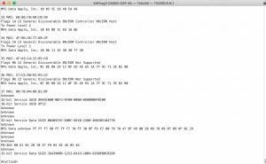
When I started this, I knew that the board had a motion sensor but I didnt know what kind. I assumed that it was an I2C based sensor, so I attached the bridge control panel and probed the I2C bus. But this is what it said:
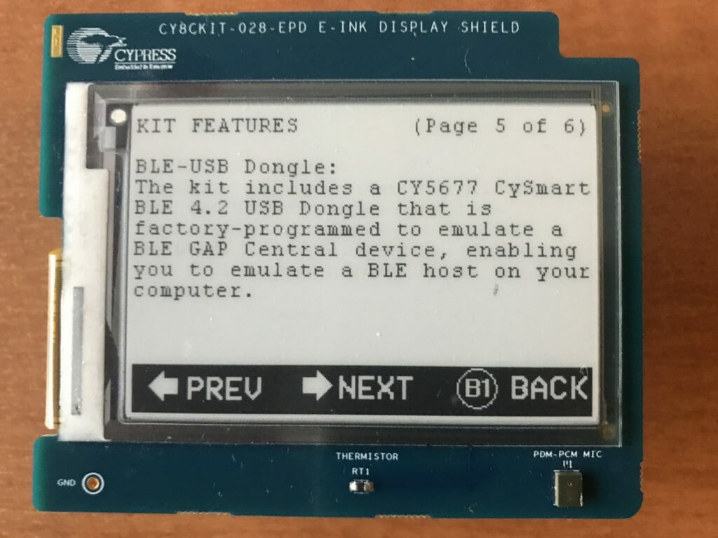
So… what the hell? Then I looked at the board to try to figure out what was going on… and low and behold… the board that I had was a prototype that was done before we added the motion sensor. Here it is:
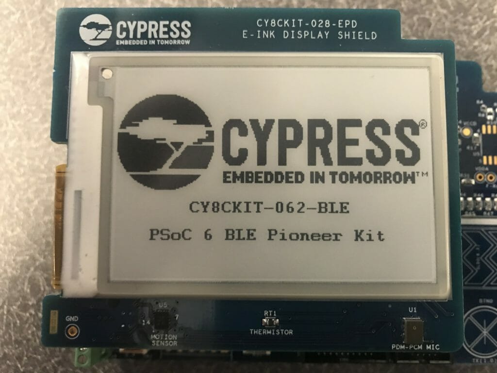
And here is a board with the sensor on it.
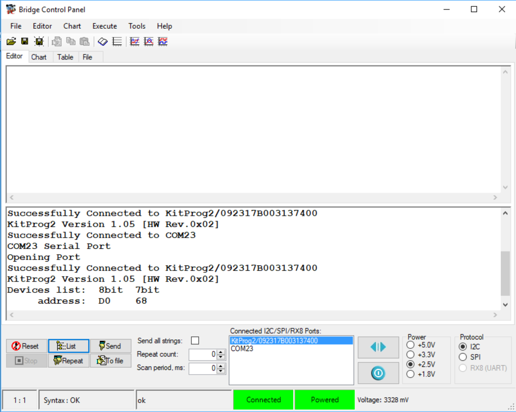
When I plug in that board and test it with the Bridge Control Panel I get:
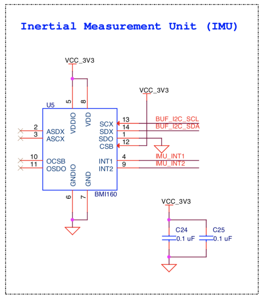
The next thing that I did was look at the schematics. OK, you can see that the Inertial Measurement Unit (IMU) is a BMI160 that is connected to the I2C bus. The other cool thing is that the devkit team hooked up the two interrupt lines. These lines are typically used for the IMU to signal the PSoC 6 that something has happened (like maybe the user started moving).
After looking at the schematics, the next step was to look at the BMI160 datasheet and try to figure out how to interface with the device. Typically these devices have a boatload of registers with a mind boggling number of bit fields. This is always the un-fun part of the process. But this time when I went to the BMI160 device page on Bosch’s website, there was a button that says “Documents and Drivers” and when you click it, there is a link to GitHub with a BMI160 driver. Score!

To make this work you just “git clone git@github.com:BoschSensortec/BMI160_driver.git”
Create New PSoC 6 project & with Bosch BMI160 driver library
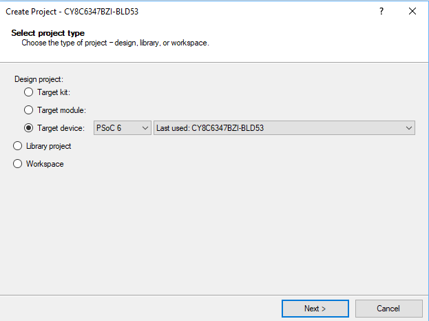
So, lets get on with testing it. First create a new PSoC 63 Project
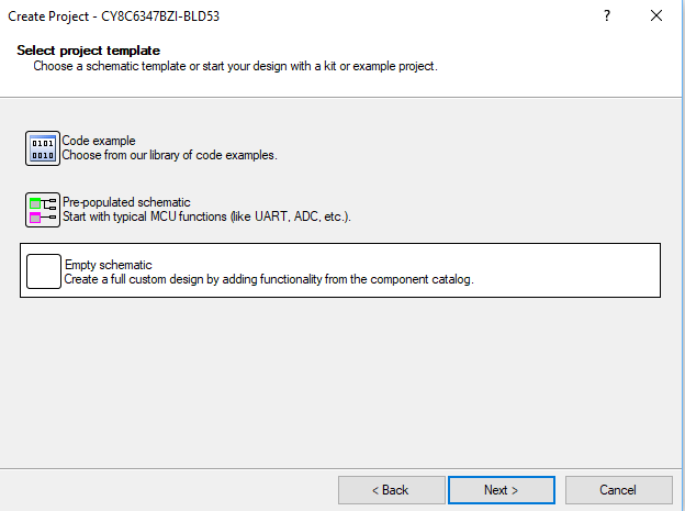
Use a blank schematic
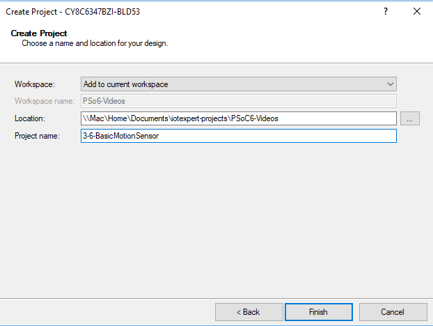
Give it a name
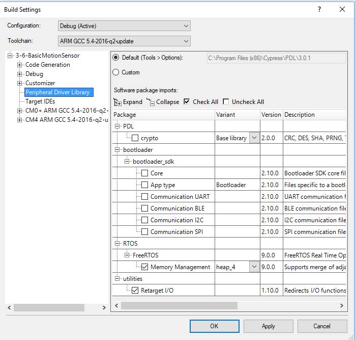
Add the Retarget I/O and FreeRTOS (from the build settings menu)
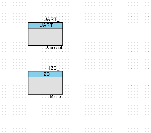
Add a UART and an I2C Master
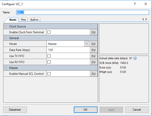
To get the I2C to be a master you need to double click it and change it into a master
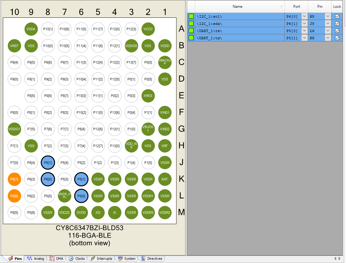
Then assign the pins
Run “Build -> Generate Application” to get all of the PDL firmware you need.
Edit stdio_user.h to use the UART (scan down the stdio_user.h to find the right place)
#include "project.h"
/* Must remain uncommented to use this utility */
#define IO_STDOUT_ENABLE
#define IO_STDIN_ENABLE
#define IO_STDOUT_UART      UART_1_HW
#define IO_STDIN_UART       UART_1_HW
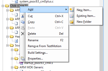
Add the “BMI_driver” directory to the include path of the CM4 project. (To get to this menu right click the project and pick “build settings”)

Add the Bosch Driver files to the project

Create the HAL for the Bosch driver
It is simple to use the Bosch driver. All you need to do is update the HAL.
- Provide a function to write I2C registers
- Provide a function to read I2C registers
- Provide a function to delay for a specified number of milliseconds
- Create a structure to hold initialization information and function pointers
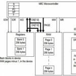
This device implements what Cypress calls the “EZI2C” protocol which is also known as an I2C EEPROM protocol. The device is organized as an array of registers. Each register has an address from 0->0xFF (a single byte of addresses). To write to a register you need to
- Send an I2C Start
- Send the 7-bit I2C address
- Send a write bit (aka a 0)
- Send the register address you want to write to (dont confuse I2C address with the internal BMI160 address)
- Send the 8-bit value that you want to write
- Send a stop
A cool thing with EZI2C is that it keeps track of the address, and automatically increments the register address each time you write. This means you can write a sequence of address without having to do a complete transaction for each address.
Given that introduction the write function is simple:
static int8_t BMI160BurstWrite(uint8_t dev_addr, uint8_t reg_addr,uint8_t *data, uint16_t len)
{

    Cy_SCB_I2C_MasterSendStart(I2C_1_HW,dev_addr,CY_SCB_I2C_WRITE_XFER,0,&I2C_1_context);
    Cy_SCB_I2C_MasterWriteByte(I2C_1_HW,reg_addr,0,&I2C_1_context);
    for(int i = 0;i<len; i++)
    {
        Cy_SCB_I2C_MasterWriteByte(I2C_1_HW,data[i],0,&I2C_1_context);
    }

    Cy_SCB_I2C_MasterSendStop(I2C_1_HW,0,&I2C_1_context);

    return 0;
}
In order to read you do a similar transaction to write. Specifically the steps are:
- Send an I2C Start
- Send the 7-bit I2c address
- Send a WRITE bit aka 0
- Send the address of the register you want to read
- Send an I2C re-start
- Read a byte
- Send a NAK
- Send a stop
The read transaction is similar to the write in that you can continue to read sequential bytes by sending an ACK. The last byte you read should be NAK-ed to tell the remote device that you are done reading. Given that the code is also straight forward.
// This function supports the BMP180 library and read I2C Registers
static int8_t BMI160BurstRead(uint8_t dev_addr, uint8_t reg_addr,uint8_t *data, uint16_t len)
{

    Cy_SCB_I2C_MasterSendStart(I2C_1_HW,dev_addr,CY_SCB_I2C_WRITE_XFER,0,&I2C_1_context);
    Cy_SCB_I2C_MasterWriteByte(I2C_1_HW,reg_addr,0,&I2C_1_context);
    Cy_SCB_I2C_MasterSendReStart(I2C_1_HW,dev_addr,CY_SCB_I2C_READ_XFER,0,&I2C_1_context);
    for(int i = 0;i<len-1; i++)
    {
        Cy_SCB_I2C_MasterReadByte(I2C_1_HW,CY_SCB_I2C_ACK,&data[i],0,&I2C_1_context);
    }
    Cy_SCB_I2C_MasterReadByte(I2C_1_HW,CY_SCB_I2C_NAK,&data[len-1],0,&I2C_1_context);

    Cy_SCB_I2C_MasterSendStop(I2C_1_HW,0,&I2C_1_context);


    return 0;
}
There is one error with both my read and write functions. And that error is? No error checking. I have seen some intermittent weirdness in which the I2C bus gets locked that ends up requiring a reset to fix. This could be prevented by checking error codes on the I2C functions.
Now that we have a read and write function we can setup our device: To do this:
- Setup a structure of type bmi160_dev
- Initialize the function pointers
- Initialize the settings for the device
- Finally send the settings
static struct bmi160_dev bmi160Dev;

static void sensorsDeviceInit(void)
{

  int8_t rslt;
  vTaskDelay(500); // guess

  /* BMI160 */
  bmi160Dev.read = (bmi160_com_fptr_t)BMI160BurstRead;
  bmi160Dev.write = (bmi160_com_fptr_t)BMI160BurstWrite;
  bmi160Dev.delay_ms = (bmi160_delay_fptr_t)vTaskDelay;

  bmi160Dev.id = BMI160_I2C_ADDR;  // I2C device address

  rslt = bmi160_init(&bmi160Dev); // initialize the device
  if (rslt == 0)
    {
      printf("BMI160 I2C connection [OK].\n");
      bmi160Dev.gyro_cfg.odr = BMI160_GYRO_ODR_800HZ;
      bmi160Dev.gyro_cfg.range = BMI160_GYRO_RANGE_125_DPS;
      bmi160Dev.gyro_cfg.bw = BMI160_GYRO_BW_OSR4_MODE;

      /* Select the power mode of Gyroscope sensor */
      bmi160Dev.gyro_cfg.power = BMI160_GYRO_NORMAL_MODE;

      bmi160Dev.accel_cfg.odr = BMI160_ACCEL_ODR_1600HZ;
      bmi160Dev.accel_cfg.range = BMI160_ACCEL_RANGE_4G;
      bmi160Dev.accel_cfg.bw = BMI160_ACCEL_BW_OSR4_AVG1;
      bmi160Dev.accel_cfg.power = BMI160_ACCEL_NORMAL_MODE;

      /* Set the sensor configuration */
      bmi160_set_sens_conf(&bmi160Dev);
      bmi160Dev.delay_ms(50);
    }
  else
    {
      printf("BMI160 I2C connection [FAIL].\n");
    }
}
Create the main firmware and test
Finally I test the firmware by running an infinite loop that prints out acceleration data.
void motionTask(void *arg)
{
    (void)arg;
    I2C_1_Start();
    sensorsDeviceInit();
    struct bmi160_sensor_data acc;

    while(1)
    {

        bmi160_get_sensor_data(BMI160_ACCEL_ONLY, &acc, NULL, &bmi160Dev);
        printf("x=%4d y=%4d z=%4d\r\n",acc.x,acc.y,acc.z,);
        vTaskDelay(200);
    }
}
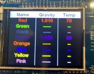
Now you should have this:

And finally the whole program in one shot
#include "project.h"
#include "FreeRTOS.h"
#include "task.h"
#include <stdio.h>
#include "bmi160.h"

static struct bmi160_dev bmi160Dev;

static int8_t BMI160BurstWrite(uint8_t dev_addr, uint8_t reg_addr,uint8_t *data, uint16_t len)
{

    Cy_SCB_I2C_MasterSendStart(I2C_1_HW,dev_addr,CY_SCB_I2C_WRITE_XFER,0,&I2C_1_context);
    Cy_SCB_I2C_MasterWriteByte(I2C_1_HW,reg_addr,0,&I2C_1_context);
    for(int i = 0;i<len; i++)
    {
        Cy_SCB_I2C_MasterWriteByte(I2C_1_HW,data[i],0,&I2C_1_context);
    }

    Cy_SCB_I2C_MasterSendStop(I2C_1_HW,0,&I2C_1_context);

    return 0;
}

// This function supports the BMP180 library and read I2C Registers
static int8_t BMI160BurstRead(uint8_t dev_addr, uint8_t reg_addr,uint8_t *data, uint16_t len)
{

    Cy_SCB_I2C_MasterSendStart(I2C_1_HW,dev_addr,CY_SCB_I2C_WRITE_XFER,0,&I2C_1_context);
    Cy_SCB_I2C_MasterWriteByte(I2C_1_HW,reg_addr,0,&I2C_1_context);
    Cy_SCB_I2C_MasterSendReStart(I2C_1_HW,dev_addr,CY_SCB_I2C_READ_XFER,0,&I2C_1_context);
    for(int i = 0;i<len-1; i++)
    {
        Cy_SCB_I2C_MasterReadByte(I2C_1_HW,CY_SCB_I2C_ACK,&data[i],0,&I2C_1_context);
    }
    Cy_SCB_I2C_MasterReadByte(I2C_1_HW,CY_SCB_I2C_NAK,&data[len-1],0,&I2C_1_context);

    Cy_SCB_I2C_MasterSendStop(I2C_1_HW,0,&I2C_1_context);


    return 0;
}


static void sensorsDeviceInit(void)
{

  int8_t rslt;
  vTaskDelay(500); // guess

  /* BMI160 */
  bmi160Dev.read = (bmi160_com_fptr_t)BMI160BurstRead;
  bmi160Dev.write = (bmi160_com_fptr_t)BMI160BurstWrite;
  bmi160Dev.delay_ms = (bmi160_delay_fptr_t)vTaskDelay;

  bmi160Dev.id = BMI160_I2C_ADDR;  // I2C device address

  rslt = bmi160_init(&bmi160Dev); // initialize the device
  if (rslt == 0)
    {
      printf("BMI160 I2C connection [OK].\n");
      bmi160Dev.gyro_cfg.odr = BMI160_GYRO_ODR_800HZ;
      bmi160Dev.gyro_cfg.range = BMI160_GYRO_RANGE_125_DPS;
      bmi160Dev.gyro_cfg.bw = BMI160_GYRO_BW_OSR4_MODE;

      /* Select the power mode of Gyroscope sensor */
      bmi160Dev.gyro_cfg.power = BMI160_GYRO_NORMAL_MODE;

      bmi160Dev.accel_cfg.odr = BMI160_ACCEL_ODR_1600HZ;
      bmi160Dev.accel_cfg.range = BMI160_ACCEL_RANGE_4G;
      bmi160Dev.accel_cfg.bw = BMI160_ACCEL_BW_OSR4_AVG1;
      bmi160Dev.accel_cfg.power = BMI160_ACCEL_NORMAL_MODE;

      /* Set the sensor configuration */
      bmi160_set_sens_conf(&bmi160Dev);
      bmi160Dev.delay_ms(50);
    }
  else
    {
      printf("BMI160 I2C connection [FAIL].\n");
    }
}
#define MAXACCEL 8000
void motionTask(void *arg)
{
    (void)arg;
    I2C_1_Start();
    sensorsDeviceInit();
    struct bmi160_sensor_data acc;

    while(1)
    {
        bmi160_get_sensor_data(BMI160_ACCEL_ONLY, &acc, NULL, &bmi160Dev);
        printf("x=%4d y=%4d z=%4d\r\n",acc.x,acc.y,acc.z);

        vTaskDelay(200);
    }
}


int main(void)
{
    __enable_irq(); /* Enable global interrupts. */

    UART_1_Start();

    xTaskCreate( motionTask, "Motion Task",400,0,1,0);
    vTaskStartScheduler();

    while(1);
}

/* [] END OF FILE */
No comment yet, add your voice below!