Now that I have shown you how to make all of the basic functions of the devkit work, I really want to make this shield into an IOT Device. In order to do this I need to:
- Get the bootloading to work (so I can put firmware into the PRoC)
- Have a scheme to communicate between between the PRoC and the Baseboard (the subject of the next posts)
- Have BLE Firmware (the subject of the next posts)
Bootloading the PRoC
When the India team sent me the shield, the EZ-USB PRoC came preprogrammed with a bootloader project. They also sent me the bootloader project that is programmed into the device. That project, called “I2C_Bootloader”, is in the workspace that you can find in the firmware directory at github.com/iotexpert/CY8CKIT-021. In order to make your own firmware application for that PRoC you need to make a reference to the bootloader project in the bootloadable component.
When I first plugged in the board I thought that I was going to have a seizure as the blue LED is blinking like crazy. That has got to go! To get firmware into the PRoC you either need to solder a header onto the board so that you can use a miniprog-3 (which I also did) and/or you can bootload the firmware. The I2C Pins on the PRoC are connected to the KitProg I2C pins on the baseboard.
Bootloading is the process of transferring a hex file image via a serial connection (I2C in this case) into the chip, then flashing it into the memory in the right place. I wrote in detail about this process in this post “The Creek: PSoC4 Bootloader + Firmware”. Here is a picture of the architecture:

First ill explain the bootloader project. This project will:
- Wait for 100ms, and if the Pin_BL_Select is held low it will start the bootloader otherwise it will start application. This was done so that you could signal the PRoC from the board that it was plugged into to start the boot loading process via a GPIO.
- If there is no application firmware or the application firmware is invalid then it will start the bootloader
- The bootloader will listen to the I2C on address 0x0B and load in firmware when it gets a request
- The application is yours to write.
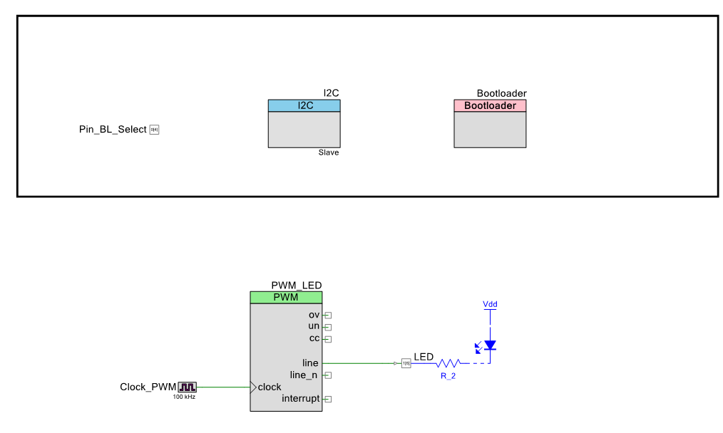
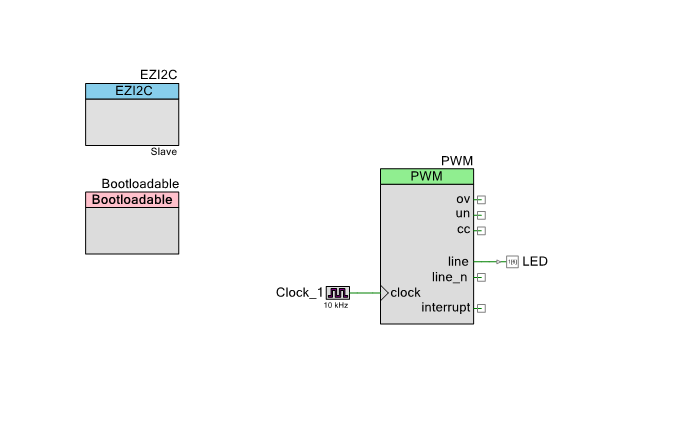
The schematic is simply a blank SCB I2C component to service the Bootloader, a GPIO pin, a blinking LED using the PWM and the Bootloader component.
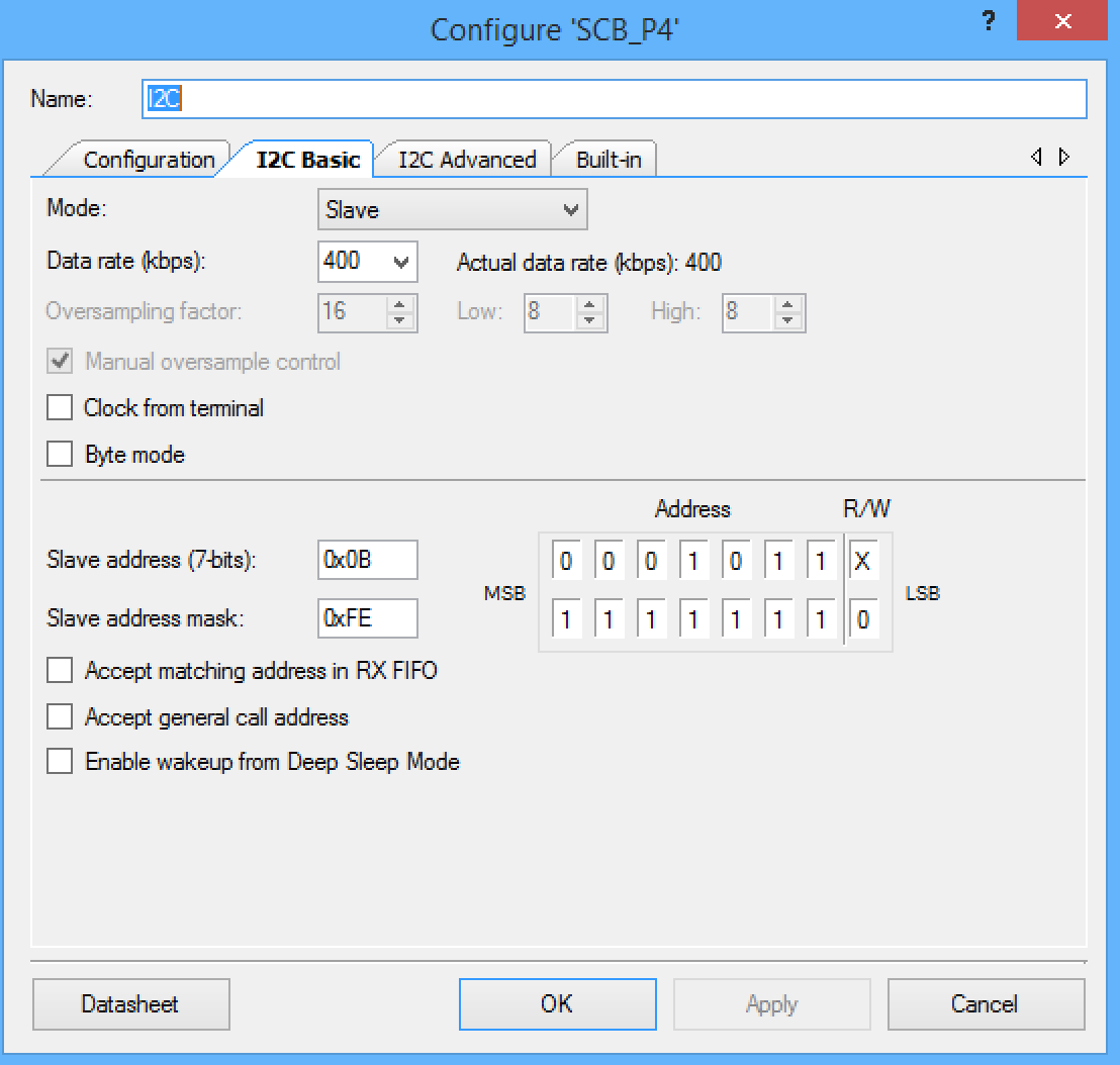
Here is the configuration of the I2C component — just 400KBS and slave address 0x0B:
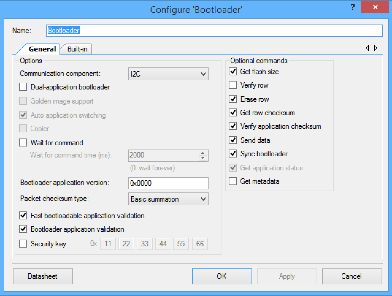
Here is the configuration of the Bootloader:
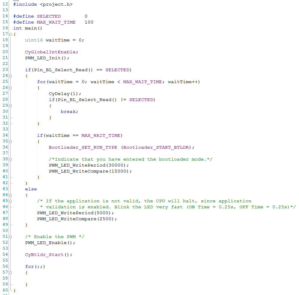
And finally the main.c
Line 23-49 are run if the digital input pin is held low when the chip is booted… indicating that you want the bootloader to start. You use this to get the PRoC back into the bootloader mode if you have already programmed firmware into it that does something else.
Line 25-32 is a loop that goes for 100ms and makes sure that the line is held down the whole time. If it is NOT held down then it break out of the loop and start the application (By falling out of the loop)
Line 34-42: if the pin was held down the whole time, then configure the the bootloader component to start
Line 54: Start the bootloader component. The component is configured to start the application immediately upon startup. If line 36 is run, then it will start the boot loading process. (this was a bit confusing to me when I first looked at this program)
A Bootloadable Application
Now that you understand the bootloader application, Ill build a simple simple bootloadable (just a program that can be loaded by the bootloader). My application will do only two things.
- It will blink the LED at 1HZ
- If will have an EzI2C component. If there is something other than “0” written to address 0 it will launch the bootloader (so you can restart the bootloader)
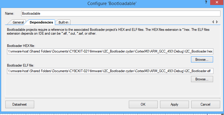
Once the schematic is configured you need to configure the bootloadable component. Basically you need to tell it where the bootloader hex file exists on your system. This is required because the bootloader and the bootloadable need to come in pairs.
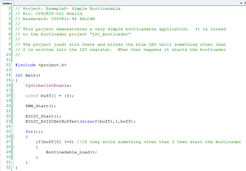
The main.c is very straightforward.
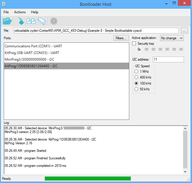
Once you have the project put together you will use the “build” menu to create the “.cyacd” file. That is just the hex file in a format that can be read by the Bootloader host. The Bootloader host know how to talk to a Cypress I2C bridge (either KitProg or MiniProg-3) and then send the CYACD file to the PRoC bootloader.
The process is
- Start the Bootloader host (from the windows start menu or by right clicking the bootloadable component)
- Find the .CYADC file for your project
- Select the KitProg and the correct I2C address (remember I set 0x0B which is also known as 11)
- Then click the “download” arrow
After each of those steps is done you will see the file being downloaded. Then you will see you the Blue LED on the kit start blinking a 1hz. Success!
If you are ready to start the bootloader again you now have two options
- Hold down the PRoC Pin P04 for 100ms as the PRoC boots
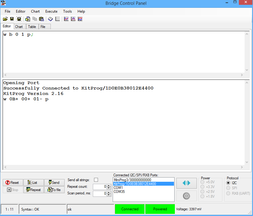
- Attach the I2C bus and write a 1 to I2C address 0x0B. The easiest way to do this is with the bridge control panel (see the picture below)
Finally, On Cypress.com we have a ton of good Application Notes and data sheets to help you understand Bootloading.
AN73854 – PSoC® 3, PSoC 4, and PSoC 5LP Introduction to Bootloaders
The Booloader and Bootloadable Component Datasheet
AN86526 – PSoC® 4 I2C Bootloader
AN73503 – PSoC® USB HID Bootloader
AN60317 – PSoC® 3 and PSoC 5LP I2C Bootloader
AN68272 – PSoC® 3, PSoC 4, and PSoC 5LP UART Bootloader
Now that you know how the bootloader and bootloadable projects work Ill address the communication between the PSoC and the PRoC in the next post.
No comment yet, add your voice below!