Summary
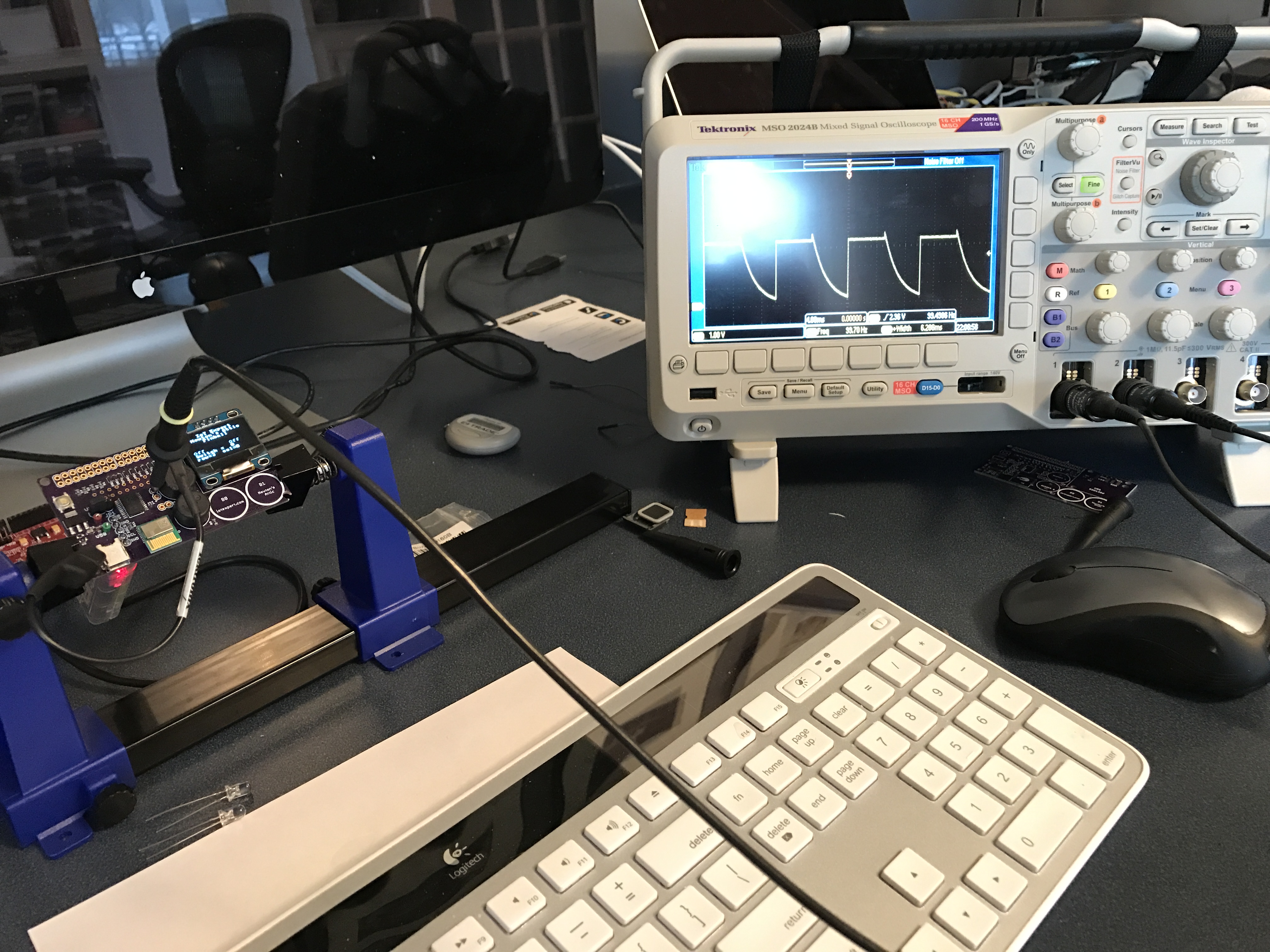
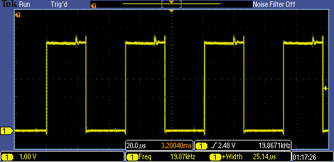
I spent a lot of time the last few days building and testing the Pinball board. This morning when I plugged in my oscilloscope to test the PSoC motor driver, I saw this:
Here is a screenshot directly from the oscilloscope. When I saw this, I wondered what was going on. Why does the driver pull-up very quickly, but have some kind of RC delay on the pull-down? This was particularly troubling as the PWM was set to 50 Hz (see on the picture where the (1) Freq is showing the measurement)
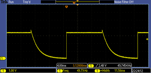
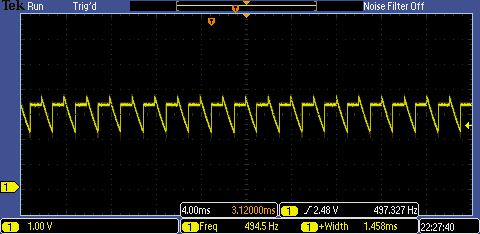
Things got much worse when I increased the frequency to 500 Hz. In fact, the motor driver doesn’t pull-down at all.
PSoC Motor Driver
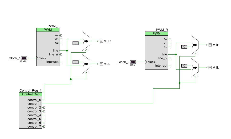
So where do I start debugging? First I looked at the PSoC Creator schematic. When you look at the schematic you can see that I took the PWM output and steered it to either M0L or M0R (or M1L or M1R). Then I used a control register to flip it.
The M0R/M0L signals are used to control the switches on the H-Bridge. Here is the actual schematic from the PCB:
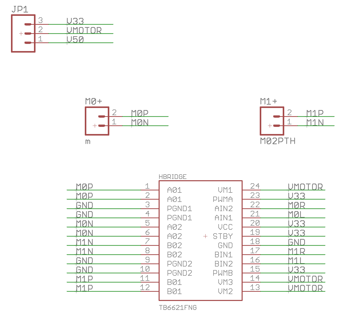
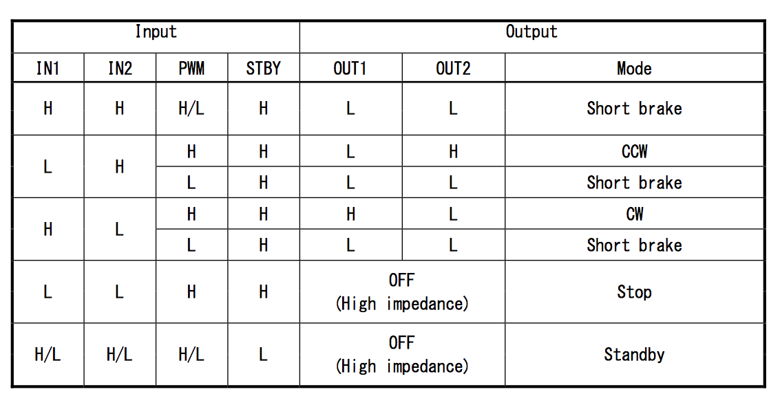
I chose the Toshiba TB6612FNG motor driver chip for this design. It has two H-Bridges built in and is the same one that we used on the PSoC 211 Robot. You can see from the schematics above that I save 1 pin by attaching the PWM input to “H(igh)” and that I pulse either In1 or In2.
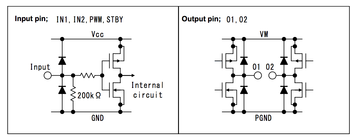
When you look at this table, or the schematic, you’ll see my problem. I connected one of the inputs to “L” That means that the NMOS switch that controls the pull-down is always off. When the PWM is low, there is no pull-down. That explains the funny RC pull-down, which is just some leakage on that node.
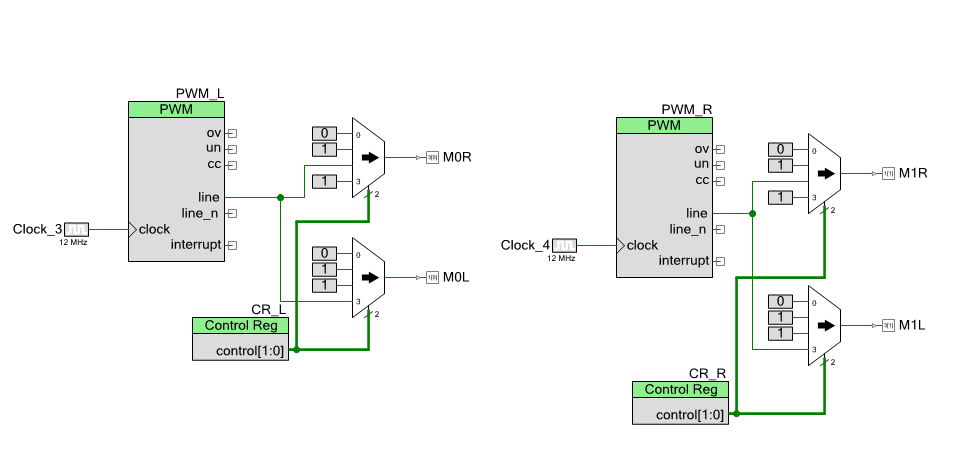
To fix this, I make this change to my PSoC Creator schematic. In this configuration I get the following:
CR=00 the output = 00 (stop)
CR=02 the output = 1PWM = CCW
CR=03 the output = PWM1 = CW
Now when I run this thing, here is what I get (at my desired 20KHz):
And finally a video showing the PSoC Motor Driver working:
No comment yet, add your voice below!