Summary
This article will take you through a high level overview of all of the parts of a TFT LCD display. The vast majority of what I have read on the internet makes this whole issue massively complex. I’m quite sure that this complexity problem is a real reflection of the serious design and manufacturing complexity in these displays and drivers. That being said, to get a conceptual understanding is much simpler, and is the point of this article.
A significant amount of my learning about this subject came from a 195 page powerpoint presentation by Dr. Fang-Hsing Wang entitled “Flat Panel Display : Principle and Driving Circuit Design“. He has graciously allowed me to reproduce a few of his images. This dude knows way way more about these circuits than I do and I would encourage you to read his work.
This article has the following subsections:
- TFT Pixel
- TFT Pixel Schematic
- TFT Panels (Also known as TFT Glass)
- TFT Gate Drivers
- TFT Source Drivers
- Gamma
- Multiplexing Gate and Source Drivers
TFT Pixel
The fundamental element in a TFT display is the liquid crystal. These elements have the property that the crystals will align from horizontal (which blocks the light) to vertical (which lets most of the light through) based on the electric field applied to them. Basically, you shine light through the liquid crystal, which blocks some or all of the light, the remainder of the white light then goes through a color filter to make red, green, or blue. It works like this:
- You use an array of LEDs to shine white light from the back of the screen towards the front (your eyes)
- Into a diffuser (to spread out the light and make it even)
- You control the orientation of the crystals using a voltage to apply an electric field to the crystals
- The white light from the back (often called the backlight) will shine through the liquid crystal elements. The amount of light coming out will depend on the orientation of the crystals.
- The white light coming out of the crystal will then go into a red, green or blue color filter making it red, green or blue (RGB)
- The light from three RGB filters will combine in your eye into a color based on the amount of red, green and blue (purple in the case below)
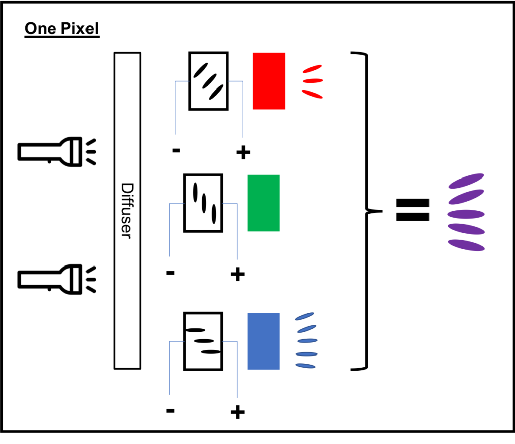
This architecture means that every pixel in the display will require a red, green and blue element. And, you will need to control the voltage on all of the elements (which will be quite a lot on a screen of any size)
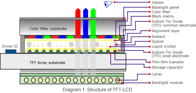
Here is a nice cross section that I found on Innolux’s website.
Pixel Schematic
What does the schematic for one element in a pixel look like? And where is the T(transistor) in the TFT? The three letter acronym TFT stands for a thin film transistor that is physically on the top of the LCD matrix right next to each liquid crystal element. Here is a schematic model for one element in the array. C-LC represents the capacitance of the liquid crystal. CS is a storage capacitor that is used to hold the electric field across the liquid crystal when the transistor is OFF. To apply a voltage across the LC you just turn on the gate and apply the correct voltage to the column commonly known as the source.
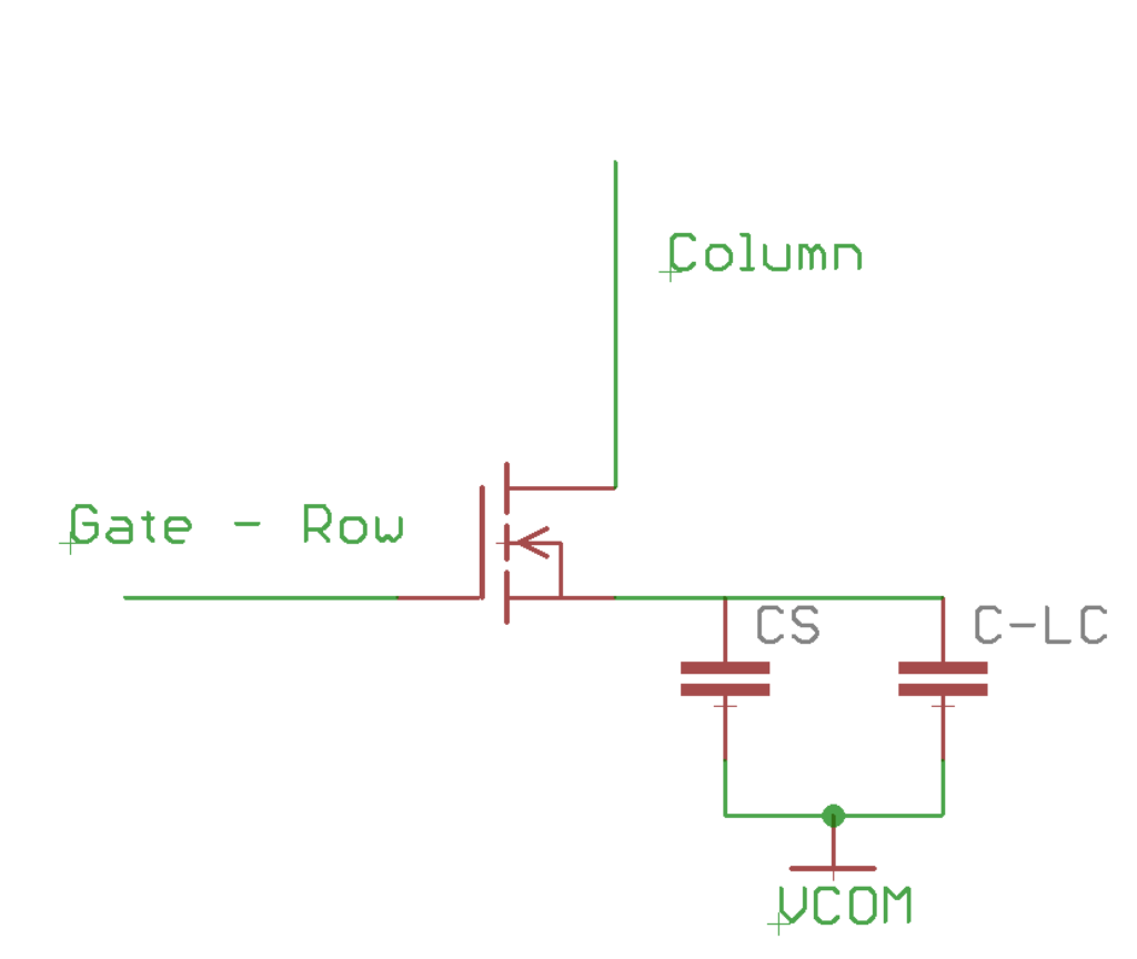
You should notice that the “back” terminal of the two capacitors is called “VCOM” and is physically on the other side of the liquid crystal matrix from the TFT. All of the liquid crystal backsides in the display are connected to the same VCOM. A bit of painfulness in this system is that the CS capacitor leaks, which means that the LCD changes state which means that each pixel must be updated, properly called refreshed, on a regular basis.
TFT Panel
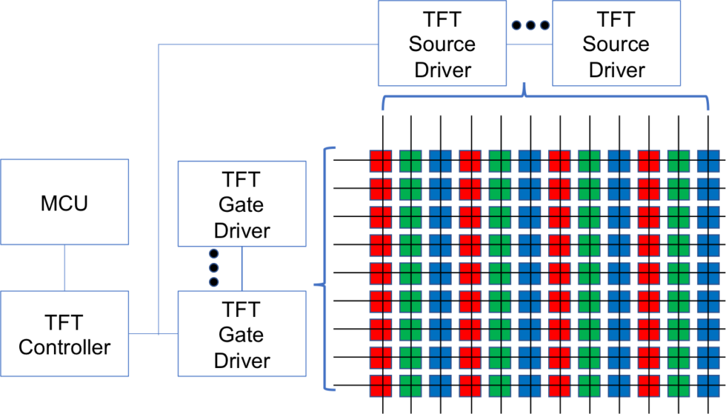
We know that each pixel has three three thin film transistors, three capacitors, three color filters (red, green and blue) and that we need to control the voltage on the source/drain of each transistor in order to cause the right amount of light to come through the liquid crystal. How do we do that? The first step is to arrange all of the pixels in a matrix. Each row of matrix has all of the gates connected together. And each column of the matrix has all of the sources tied together. In order to address a specific pixel RGB element, you turn on the correct row and then apply a voltage to the correct column at the right time.
If you have been thinking about this system you might have done a little bit of math and figured out that you are going to need an absolute boatload of source and gate driver signals. And you would be right! For example, a 4.3″ screen with 480×272 will require 480x272x3 elements which are probably organized into 480 rows by 816 columns. This would require a chip with at least 480+816=1296 pins, that is a lot. It turns out that for small screens <=3.5″ there are chips with enough pins to do the job. But, for larger screens, it requires multiple chips to do the job. The “…” in the picture above shows the driver chips being cascaded. The next thing to know is that “TFT Glass” usually has the driver chip(s) embedded into the screen at the edge (you can see that in the picture from Innolux above).
TFT Gate Drivers
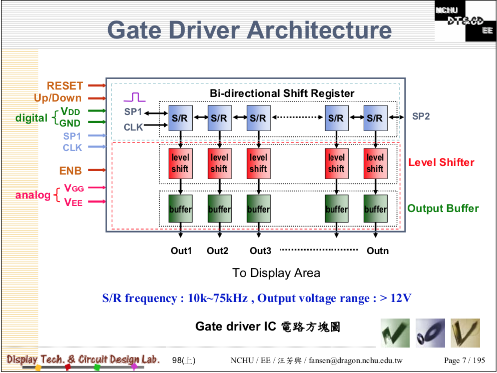
You must put a quite high voltage source >20v and drain <-10V across the liquid crystal at the right time to get it to do its thing. In order to pass that source voltage, the gate must be turned on at the right time to the right voltage, this is the purpose of the Gate Driver IC. The gate driver is conceptually simple and Dr. Wang drew a nice picture on page 7 of his presentation. You can see that it is basically a shift register, with one element per gate. You shift in a “1” and then clock it through the entire shift register which will have the effect of applying a 1 to each gate.
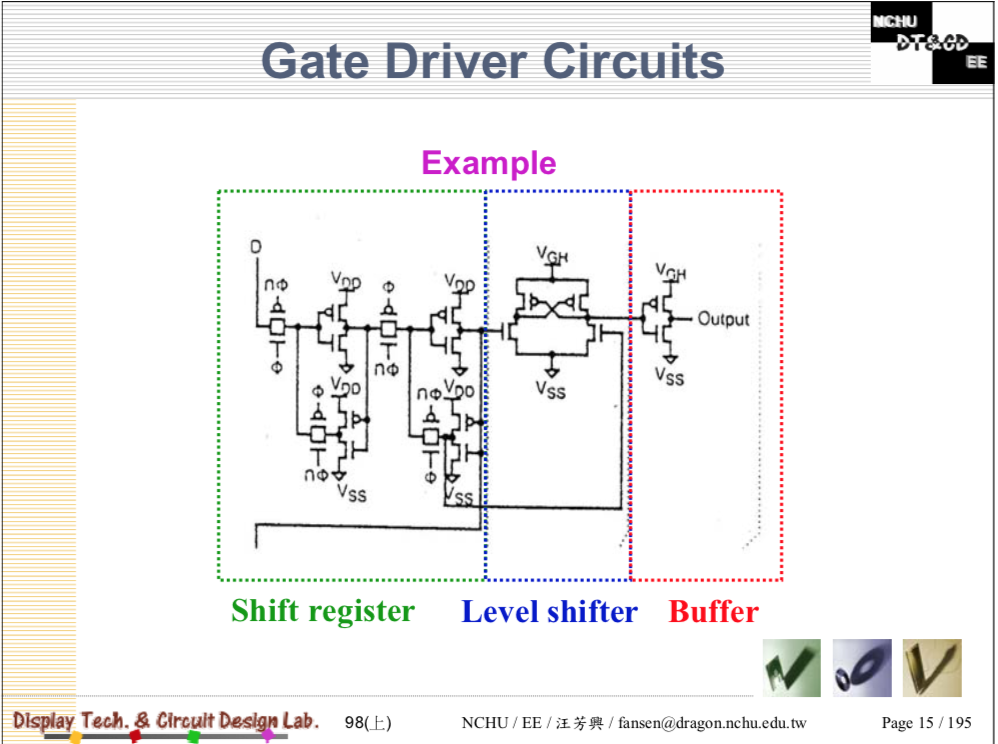
However, a 3.3v logic 1 is not anywhere high enough to drive the gate so that it can pass the much higher source voltage. So, you need to level shifter and a buffer to get the “right” voltage. On page 15, Dr. Wang made a nice picture of this circuit as well.
It turns out that this picture is conceptually correct, but the exact implementation has “a lot going on”. You can read about the next layer of circuit design in his presentation on pages 15-35.
TFT Source Drivers
In its most basic form, the TFT source driver is responsible for taking an 8-bit digital input value representing the value of an individual LCD element and turning it into a voltage, the driving the voltage. Like this:
You could conceptually have one DAC per column in the panel. But this would have at least two problems
- The DACs are big circuits and this would make for giant source driver chips
- You would need to “save” all of the digital values for an entire row so that when you turned on the row, you could turn on all of the DACs on at the same time.
You could conceptually also have one DAC for all of the columns, but this would have a bunch of problems including:
- The DAC would have to be strong enough to drive all of the columns
- You would need 3x the number of row drivers to effectively de-mux the column
- You would need 1 pin on the source driver per column in the panel (for an 800×600 lcd that would be 600×3 = 1800 pins)
In reality there is some compromise of chip size, number of pins and time that is made by multiplexing pins, columns and rows. For example, many of the small screens appear to have 1 column driver for all of the reds, 1 driver for the blues and one for greens.
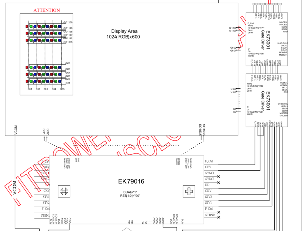
What appears to happen in real life on bigger screens is some combination of column and row multiplexing. In one display that I found there were 2x the number of rows which allows the columns to be multiplexed 2-1. The display is 1024×600. That requires 1024*3 RGBs in the column = 1536 pins. This means that you need to double the number of gate drivers, resulting in 1200 pins in the row direction. Here is a picture from their datasheet.
Gamma Correction
The last issue that I will address in TFT LCD drivers is called Gamma Correction or more simply Gamma. Gamma is an intensity adjustment factor. For any given digital intensity input, you will need a non-linear translation to a voltage output on the source. For example a doubling of digital input (so that a pixel appears twice as bright) you will not double but instead will have some non-linear translation of the output voltage.
There appear to be a bunch of reason why you need Gamma Correction including at least:
- Your eye perceives light intensity in a non-linear way
- The LCD panel responds differently based on the input
- The intensity variance is dependent on the color
The good news is that this gamma correction is built into the display drivers. From my reading, this is sometimes done with digital processing, and sometimes done with an analog circuit. But in general, it appears to be tuned and programmed into the driver by the panel vendor for these smaller display.
In the next article I will write about TFT Controllers.
Embedded Graphics Index
Embedded Graphics
Embedded Graphics Overview
TFT Displays & Drivers
TFT Controllers
PSoC 6 + Segger EmWin + MCUFriend 2.4" TFT - Part 1
PSoC 6 + Segger EmWin + MCUFriend 2.4" TFT - Part 2
MCU Friend 3.5" Identification


No comment yet, add your voice below!