One of the common open source development tools is called the Bus Pirate. It is a low cost ($35) serial terminal based program that can issue commands to many (and mostly serial) busses including UART, SPI, 1-2-3 wire and I2C. Bus Pirate was developed by Ian Lesnet of Dangerous Prototypes.
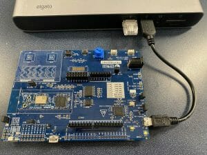
I am currently working on a project for a friend of mine (more to come on this topic) that will read data from 3 different I2C sensors, record the data into a nonvolatile RAM and simultaneously broadcast it over a BLE Radio. As such, I had a need to make sure that I understood the way that these sensors behave.
The bus pirate has had 4 major revisions and many subrevisions. The current “stable” version is V3, however, there is a fairly new version V4 which has many improvements and should soon displace V3.
Initially I bought a V3 bus pirate from Sparkfun and the Sparkfun cable, which I thought would be cool. 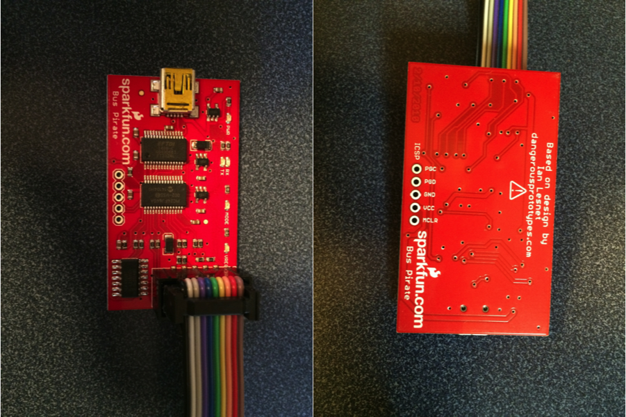
I started by plugging the BP into a USB port, where it proceeded to enumerate as something my computer had never seen before. Great. I looked around a bit and figured out that the designer had used a FTDI USB to Serial bridge chip as part of the design. This chip required a custom driver which I found on FTDIs driver website. This requirement was also documented in the Bus Pirate 101 tutorial. It is kind of too bad that FTDI hasn’t gotten their driver to be understood by Windows without intervention. Just one more good reason to use the Cypress USB Serial Chip.
After sorting out the driver situation I attached to the Bus Pirate using my favorite terminal program – Putty. You can see (by looking at the Device Manager) that the BP enumerated as COM5 on my computer.

The first thing that I tried (without having yet looked at the instructions was “?” which nicely gave a list of the commands (as you can see in the screenshot below).
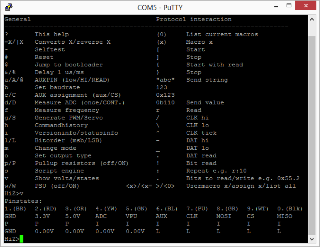
I then tried “v” which shows the states of the 10 pins. Cool. My first though was “which wire on this cable is pin 1?” Then I looked at the screen and realized “wow… look at that, the wires on the cable are the same color as the labels on the screen”. I though that was pretty damn civilized. I had a variable voltage sitting right next to the kit (just a POT on another devkit that I was working on) so I plugged it into the “YW” (aka Yellow) wire. After pressing v again it happily reported 0.00v (two decimal places even). Hmmm… what in the world is going on. Time for the fluke. Crazy, the voltage is right, I wonder what isnt working. I then guessed that the cable was plugged in backwards, but that wasnt it (the cable is keyed). Then I wondered if there was something wrong with the cable, so I disconnected it and just connected directly to the pin (which is unlabeled on the silkscreen – that sucks). I found the pinout on the schematic on Dangerous Prototypes. Then I realized, the cable is BACKWARDS from the real pinout. That really really sucks.
When I looked at the comments on the Sparkfun page there is quite the little discussion about this topic. Included is a suggestion to un-crimp the cable, flip it over, and recrimp. I tried this suggestion and it worked out, until I broke part of the plastic holding the cable together. After getting the voltage source connected to pin 4 I was able to see changes in the value being read correctly by the analog to digital convertor in the BP. Cool.
The other comment which caught my attention on the Sparkfun page was a request from Ian Lesnet to please buy from the SeeedStudio website. This motivated me to purchase another V3 and a V4 from SeeedStudio. I the next post Ill talk more about my experience with SeeedStudio V3 and V4.

No comment yet, add your voice below!