Summary
As I have been working my way through understanding the Matrix Orbital displays, I think that the whole scheme for programming them is very clever. The bottom line of this article is that Matrix Orbital created a command language for making things work in the display, then the built the rest of their toolset around that language. In this article Ill show you how it is all connected.
A Buffer Full of Mystery
While I was trying to understand how the GTT Support Tool works, I send a “Reset Module” also known as {254, 1}. When I ran the script, the screen rebooted, and then the serial monitor dumped out a boat load of stuff. You can see it in the picture below:
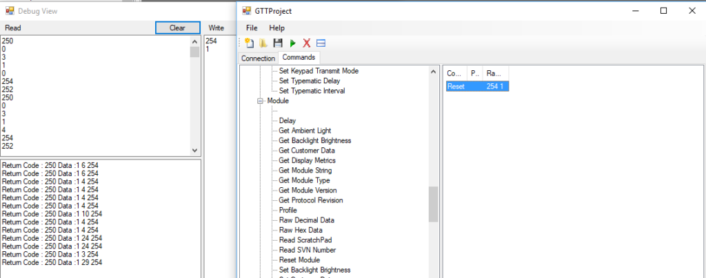
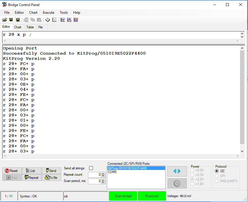
This was not very different than when I first attached to the screen using the Bridge Control Panel. Here are the first I2C reads after the reboot.
So, what is all of this stuff? The answer to that question resides in how this whole thing is put together.
GTT Scripts
All interactions with the display are done via the command language. There are multiple paths for sending commands to the screen, the ones we have talked about so far, I2C, USB and UART. And the one path that I have not specifically talked about but works exactly the same way, the mass storage sd-card.
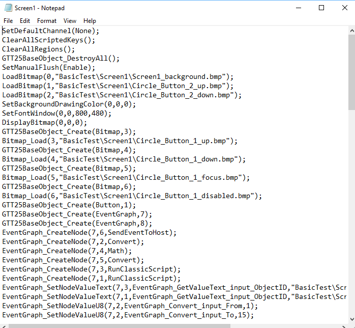
When you design a screen in GTT Designer, what it does is take that screen, and spit out a text based command language. Here is a screenshot of that for the test project that I am working on.
Then GTT Designer compiles the text into a binary file with the GTT2.0 and GTT2.5 commands. You can look at the binary file with a binary file editor. Here it is for Screen1.bin
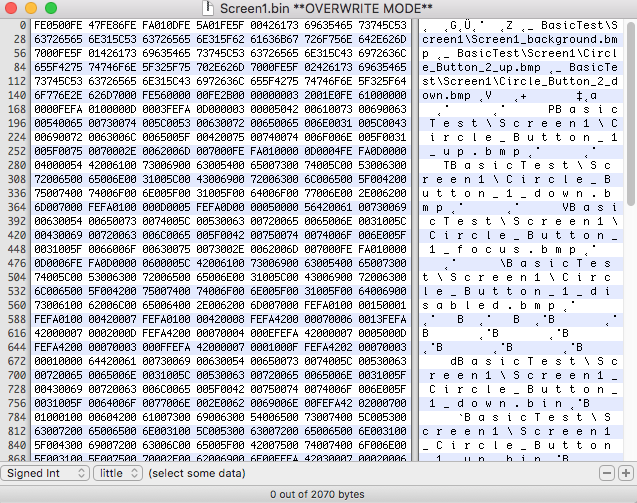
And you should recognize the bytes you see. Look at the top and you will see {FE, 05, 00} which in decimal is {254, 05, 00} and if you look in the GTT20 manual you will find that is “Set Communication Channel to None”. Here is the screenshot from the manual.

But, what happens when the device boots? Well, they followed the lead from MS-DOS and created a file called “autoexec”. And, if you look in that file they so graciously tell you what happens.
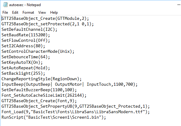
How cool is that? All of these commands are just the things that you did on the project setting and the display settings. And the last line of the file launches just launches Screen1.bin, which is just the binary file of the commands it takes to load the Screen1.
Now back to the original question. What is the buffer full of mystery? Simple, it is the output of all of the commands (if they make output) that are in the autoexec binary and the screen1 binary. If you had happened to set the default channel to “none” you will find that the buffer doesnt have anything in it… which should make sense.
So, when the manual says to delete the autoexec at the top level directory in order to reset the board. All that does it remove all of the settings that you created in your project.
The only thing that I wish is that they gave you access to the txt–>bin compiler. But oh well.
You can "git" these projects from https://github.com/iotexpert/GTT43A And the driver library from https://github.com/iotexpert/GTT-Client-Library
Title
Matrix Orbital GTT43: A Cool Display
Matrix Orbital GTT43A: Serial Interface
Matrix Orbital GTT43A: GTT Scripts
Matrix Orbital GTT43A: A PSoC 4 Interface
Matrix Orbital GTT43A: Debugging the I2C
Matrix Orbital GTT43A: GTT Driver Library - Part 1
Matrix Orbital GTT43A: GTT Driver Library - Part 1
Matrix Orbital GTT43A: PSoC 6 using RTOS and the GTT Driver Library
No comment yet, add your voice below!