Summary
I recently was working on a project that had a line of code that sometimes caused the system to hang. One of the several possible fixes to my problem was to use a Watch Dog Timer (WDT). I “knew” about the PSoC4 Watch Dog Timer(s) in the PSoC4 family but had never used them. My experiments are the subject of this article. I will address the following areas.
- PSoC4 Watch Dog Timer: Introduction
- PSoC4 Watch Dog Timer: Basic Usage
- PSoC4 Watch Dog Timer: Callback
- PSoC4 Watch Dog Timer: Custom ISR
All of these projects are available on my GitHub website of you can “git@github.com:iotexpert/PSoC4-WDTExamples.git”
PSoC4 Watch Dog Timer: Introduction
Inside of most of the PSoC4 family there are two 16-bit timers Timer0-1/WDT0-1 and one 32-bit timer called Timer2/WDT2. These timers are driven by the Low Frequency Clock (LFCLK). In addition, they can be cascaded together to form a larger timer (I’m not sure why you would need a 64-bit timer) or they can be used in isolation as general purpose or WDTs. You can configure these timers either through software or on the clocks tab of the design wide resources (DWR). For some reason, which I don’t understand, Cypress choose not to use the optional ARM Cortex-M family Watchdog Timer.
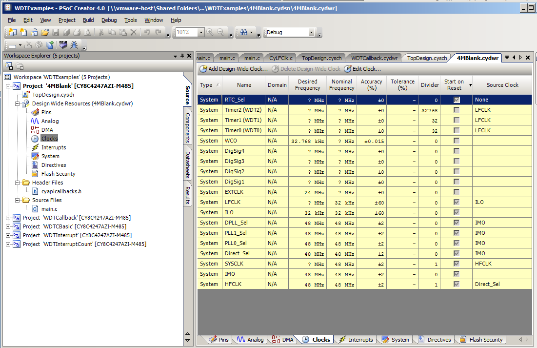
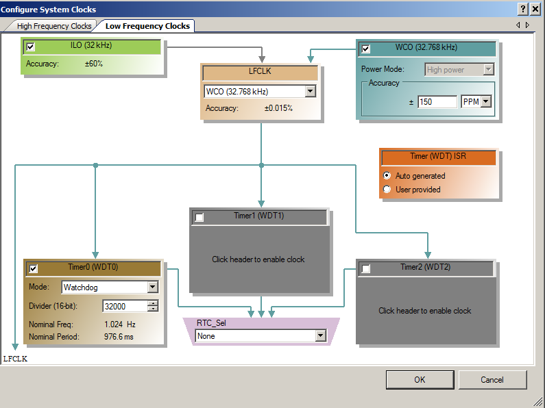
I started this article by creating a PSoC4M project called “4MBlank. In the screenshot below you can see that I have clicked the “Clocks” button in the DWR. On the 2-3-4 line you can see the Watch Dog Timers. To edit the low frequency clocks press the “Edit Clock” button. (as shown on the 2nd screen shot)
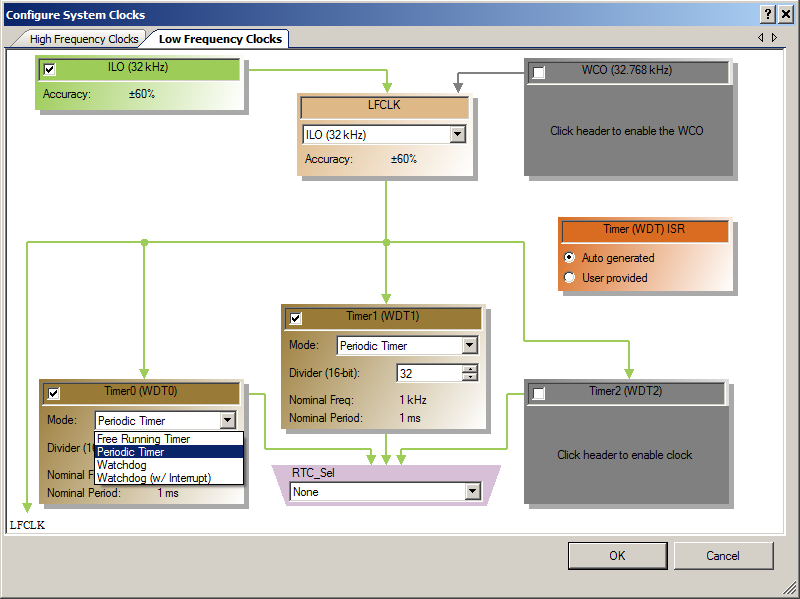
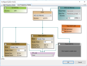
In the PSoC4M it is possible to drive the LFCLK with two different oscillators, the Internal Low-speed Oscillator (ILO) which is a very inaccurate RC Oscillator or with an external Watch Crystal Oscillator (WCO) which is very accurate. The CY8CKIT-044 has the WCO on the board so I will be able to use it as the LFCLK source for my projects. To select the LFCLK source use the dropdown menu (currently set on ILO). Each of the timers can be put into one of four modes (from the LFCLK Datasheet)
- Free Running Timer – Does not generate an interrupt or reset. You can read the counter and set an interrupt in the firmware to generate occasional timing loops.
- Periodic Timer – Generates an interrupt on a match event but no reset. The timer wraps at the set divider value.
- Watchdog – Generates a reset on a match event (counter should be cleared before reaching a match event to prevent a reset).
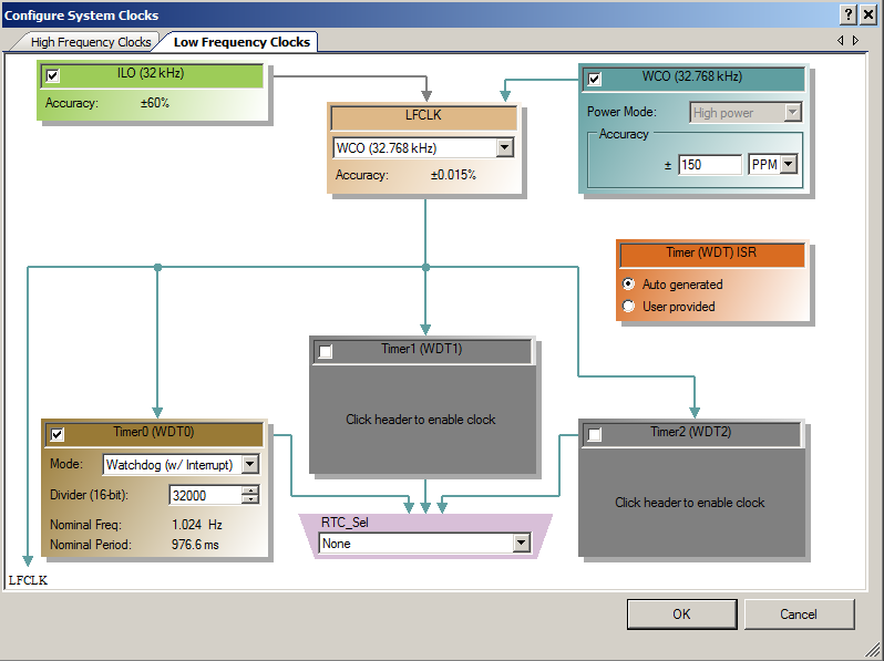
- Watchdog (w/interrupts) – Generates an interrupt on a match event and generates a reset on a 3rd unserviced interrupt.
In addition it is possible to cascade the timers (to make large timer), however, this must be done through the APIs. I will explain the “Timer ISR” box in the last example project. To enable a Timer click the little box in the upper left hand corner. (in the picture you can see Timer0 and Timer1 are enabled). When you configure the timer you can select its function as well as its divider which sets how often it is triggered based on the frequency of the input source.
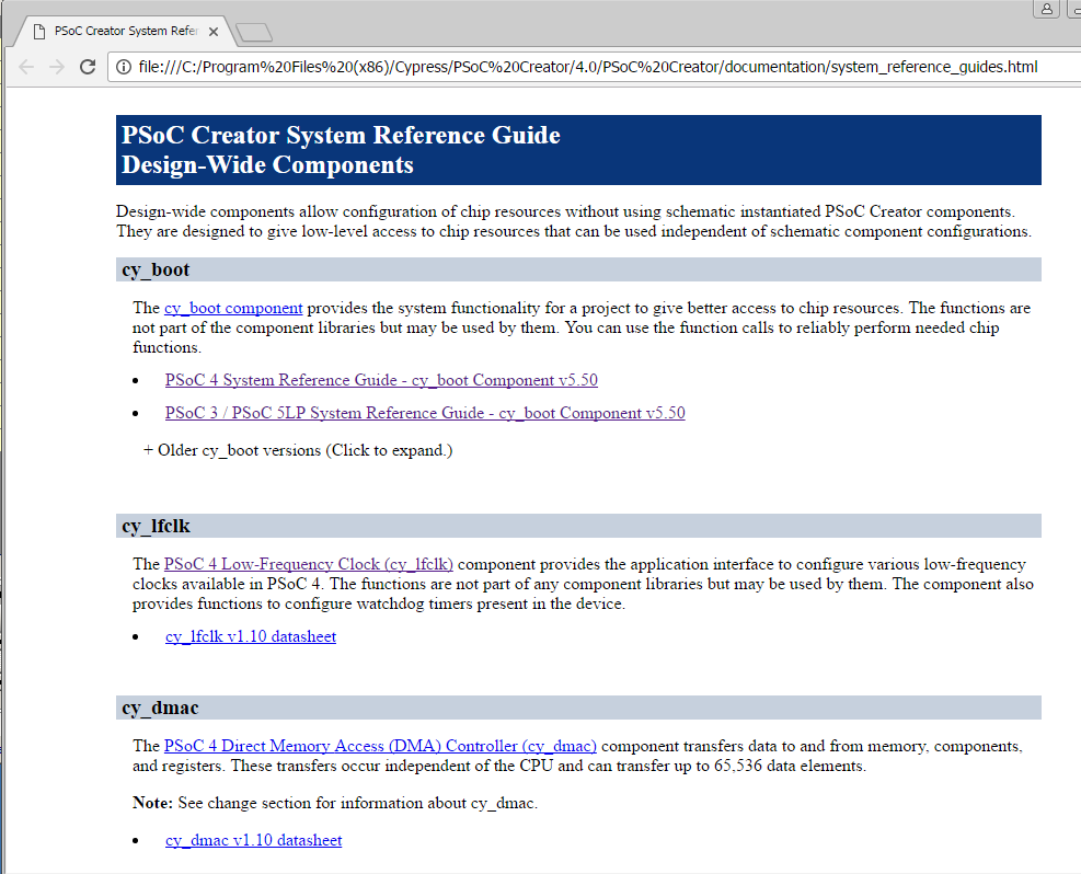
All of the documentation is available on the Help–>System Reference Guide. Then click the “PSoC4 Low Frequency Clock” link.
PSoC4 Watch Dog Timer: Basic Usage
The first project shows the use of the WDT to reset the chip. This project starts by configuring the WDT to use the WCO as its source clock and to have a period of about 1 second. With this configuration if you don’t “feed” the WDT it will cause a chip reset in 3 seconds.
When the PSoC4 chip is reset you can find the cause of the reset by using the API “CySysGetResetReason”. This will return the cause of the last reset
- CY_SYS_RESET_WDT – WDT caused a reset
- CY_SYS_RESET_PROTFAULT – Occured protection violation that requires reset
- CY_SYS_RESET_SW – Cortex-M0 requested a system reset.
My program looks for a WDT Reset, and if that happens it turns on the Red LED and hangs the program with an infinite while loop. If it was a normal (XRES or Power up) boot of the chip it will just run the infinite for loop.
In the main loop of the program you can see that it blinks the Blue LED quickly (5 Hz)… then if you don’t feed the WDT it resets the chip. If you uncomment the “CySysWatchDogFeed” the chip will continue to blink the Blue LED until the end of time.
#include "project.h"

int main(void)
{
    CyGlobalIntEnable; /* Enable global interrupts. */

    if(CySysGetResetReason(CY_SYS_RESET_WDT) == CY_SYS_RESET_WDT )
    {
        CySysWdtDisable(CY_SYS_WDT_COUNTER0_MASK);
        red_Write(0); // turn on the red LED
        while(1);     // hang
    }

    for(;;)
    {
        blue_Write(~blue_Read());
        // If dont feed the WDT it will cause a reset in ~3 seconds
        //CySysWatchdogFeed(CY_SYS_WDT_COUNTER0);
        CyDelay(100);

    }
}
PSoC4 Watch Dog Timer: Callback
Instead of just reseting the chip on the 3rd match of the WDT timer, you can ask to be called via an interrupt when the match occurs. To accomplish this, start by configuring one or more of the WDT Timers to a “Watchdog (w/ Interrupt)”. When you select “w/Interrupt” you can either use an ISR that Cypress provides or you can create your own ISR.
The ISR that Cypress provides does two basic things. First, if you have registered your interest in being called back, it calls your callback subroutine. After the three callbacks are done, it resets the counters and clears the WDT. In the block of code below you can see on Line 20 that I register my call back. The routine “wdtInterruptCallback()” is then called each time that WDT Timer expires, A.K.A about 1/second. This makes the Blue LED bink on/off. The other interesting thing in this code is that I show that the chip can be put into deep sleep and the WDT will continue to run.
#include "project.h"

void wdtInterruptCallback()
{
    blue_Write(~blue_Read());
}


int main(void)
{
    CyGlobalIntEnable;

    if(CySysGetResetReason(CY_SYS_RESET_WDT) == CY_SYS_RESET_WDT )
    {
        CySysWdtDisable(CY_SYS_WDT_COUNTER0_MASK); // Disable the WDT
        red_Write(0); // Turn on the red LED
        while(1);     // Hang
    }

    CySysWdtSetInterruptCallback(CY_SYS_WDT_COUNTER0,wdtInterruptCallback);

    for(;;)
    {
        CySysPmDeepSleep(); // Put the chip into deep sleep.
    }
}
PSoC4 Watch Dog Timer: Custom ISR
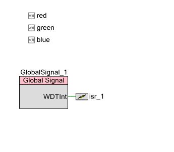
If you do not want to use the Cypress provided ISR you can create your own. In order to do this you need to add the ISR and Global Signal components to your schematic:
This will attach the WDT Interrupt Signal to the NVIC. In your source code you will need to provide the handler function for isr_1. My custom ISR is called “wdtInterruptHandler”. All it does is toggle the Blue LED, then clear the WDT Interrupt.
#include "project.h"

void wdtInterruptHandler()
{
    blue_Write(~blue_Read());
    CySysWdtClearInterrupt(CY_SYS_WDT_COUNTER0_INT);

}


int main(void)
{

    if(CySysGetResetReason(CY_SYS_RESET_WDT) == CY_SYS_RESET_WDT )
    {
        red_Write(0); // turn on the red LED
        while(1);     // hang
    }

    CyGlobalIntEnable; /* Enable global interrupts. */


    isr_1_StartEx(wdtInterruptHandler);

    CySysWdtEnable(CY_SYS_WDT_COUNTER0);

    for(;;)
    {
        CySysPmDeepSleep();

    }
}
PSoC4 Watch Dog Timer: Watch Dog Reset
As I was reading all of the documentation I started thinking about how I could write a program that could show that three unserviced interrupts would cause the reset. I originally thought that I could put a counter in the ISR and then reset the the WDT on the 3rd call, however, that does not work because when you return from the ISR, the WDT Interrupt is still pending. When the interrupt is still pending it just jumps right back into the ISR. In order to show the three unserviced calls, I created the program below which starts toggling a pin as fast as possible when the ISR is called. This loop ends only when the chip is reset.
#include "project.h"

void wdtInterruptHandler()
{
    while(1) WDTSignal1_Write(~WDTSignal1_Read());
}

int main(void)
{

    WDTSignal0_Write(1);

    if(CySysGetResetReason(CY_SYS_RESET_WDT) == CY_SYS_RESET_WDT )
    {
        CySysWdtDisable(CY_SYS_WDT_COUNTER0_MASK);
        red_Write(0); // turn on the red LED
        while(1);     // hang
    }

    isr_1_StartEx(wdtInterruptHandler);

    CySysWdtEnable(CY_SYS_WDT_COUNTER0);
    CyGlobalIntEnable; /* Enable global interrupts. */

    for(;;)
    {
    }
}
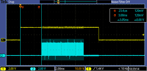
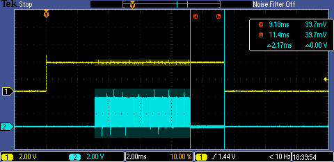
I configured the period for the WDT to be ~3ms. The yellow trace labeled “1” is a pin that is written to 1 by the main loop when the chip starts main(). You can see that the time from main starting until the ISR starts toggling is about 3ms.
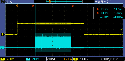
Then inside of the ISR you can see that the toggling goes on for about 6ms (a.k.a two WDT periods)
Finally, you can see the chip reset, then reboot, which takes about 2ms. You do not see the rising edge in main on the last picture because it takes about 500ms for the WCO to stabilize and main to start.
7 Comments
Hi Alan,
I like your blog and the information given on the WDT/Timer. Thanks!
Please can you comment on the (dis)advantages of Callback vs. Custom ISR. Basically in both examples you have used your customized function to toggle the LED.
In my opinion:
Callback:
+ Start/activation of ISR is done automatically
+ No need to take care of clearing the IRQ flag
– The IRQ priority cannot be set individually (BTW, which priority is used for this method?)
– The used IRQ is not shown within the schematic
– Longer latency time
Custom ISR
+ IRQ is shown in the schematic
+ The IRQ priority can be set within the Interrupt tab of the *.cydwr
+ Shorter latency time
– Interrupt handler needs to be started manually
– interrupt flag must be cleared manually
Well, beside of the priority level and maybe the latency time impact I do not really see that big difference between both methods.
Please, if there is more than listed above, highlight pros and cons for each.
Again thanks for your blog. it’s great!
Holger
I think that your summary is spot on. The callback scheme is for sure slower, a few function calls and returns… but it offers connivence. The reality is that the same tasks need to be done and it is a choice to let Creator do it for you… or you have to do it yourself. I suppose that unless I have something really timing critical I probably use the callback scheme.
Can we generate more than 2 sec of deep sleep interval by watchdog timers?
Sure. You can cascade the WDTs together using the CySysWdtSetCascade(CY_SYS_WDT_CASCADE_01); You can read about this win the LFClock reference guide. Ill also post an example next week on Tuesday.
Here is an article about it. https://iotexpert.com/2017/11/21/psoc-4200m-wdt-long-deep-sleep/
I am glad I stumbled upon this. The Cypress docs are rather underwhelming in their lack of detail. Thanks, Alan.
You are welcome… not to be argumentative, actually I think that Cypress overall does an excellent job with our documentation. Obviously we have holes in the experience, but we do put a significant amount of effort into it.