Summary
In this article I will walk you through the first steps of building a complete Type-C power supply that will look like this:

The Project
I have been working on a project that will drive several strings of WS2812 LEDs. Specifically, a CapSense dimmable “IoT-ified” nightlight using a PSoC 6 attached to a CYW43012 attached to a string of WS2812 LEDs. Right now, I have this thing built up with a development kit + a breadboard + 2 wall warts and it is sitting on the floor beside my bed.
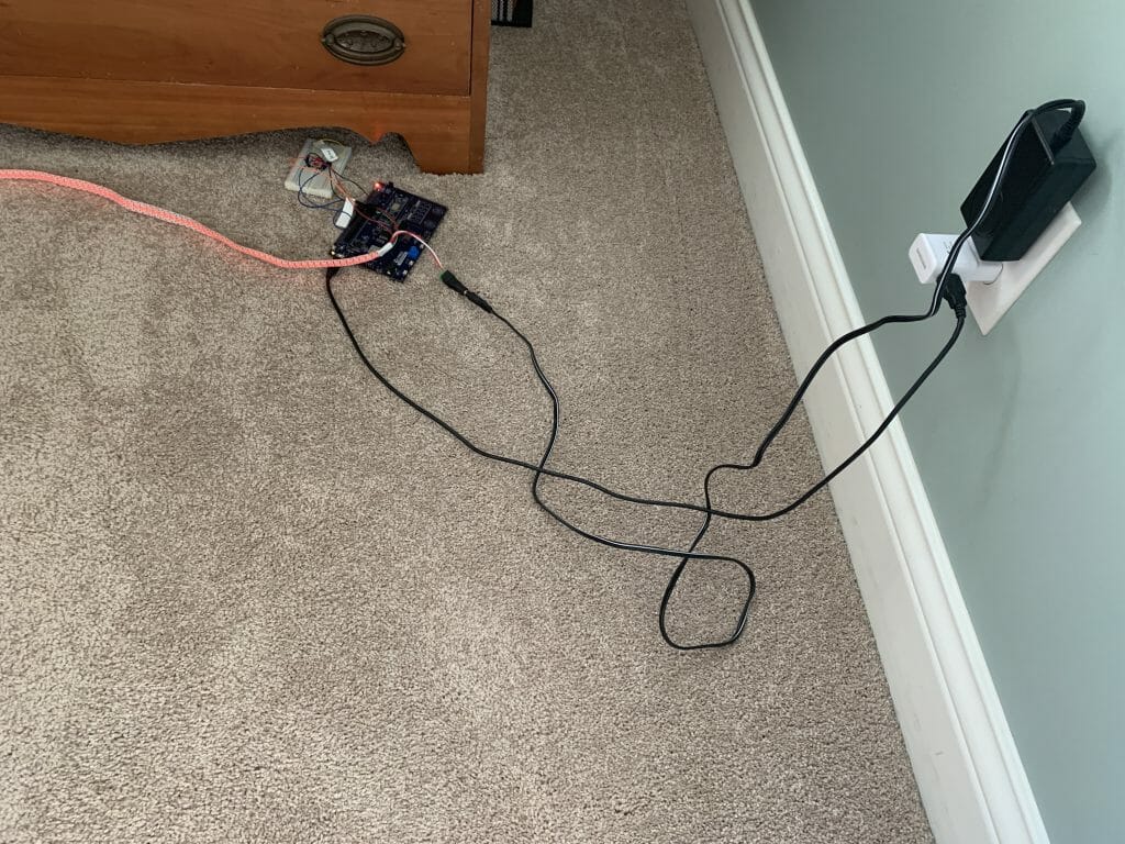
When you see this picture, I’m sure that you are thinking. “You are probably going to be sleeping on the floor beside your bed if you don’t do something better than that.” And you would be right. I know that I want a single PCB in a nice 3-d printed box that does all of this. I also know that I want to use Type-C instead of a normal 12v wall wart. When I started this I had only the vaguest ideas about how to turn Type-C into something that could drive a bunch of LEDs and a PSoC. How much power do I need? And at what voltages? That seemed like the first question that needed answering.
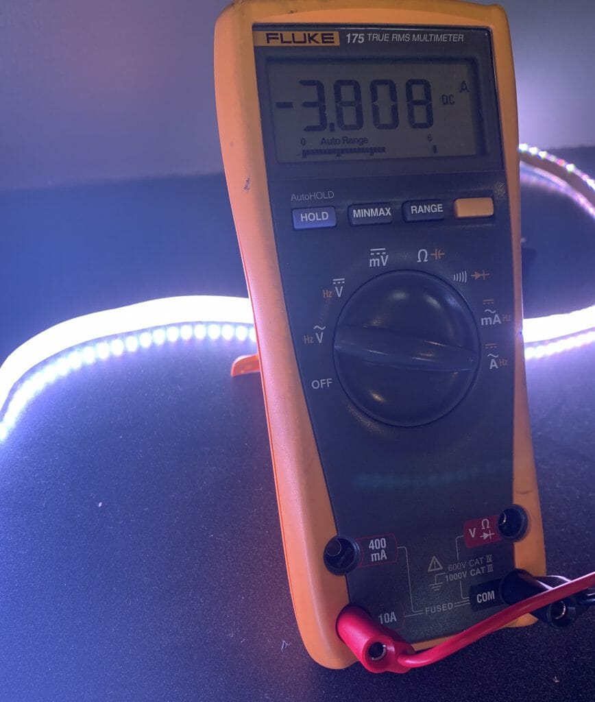
First, I put a meter on a string of 144 WS2812 LEDs. Wow, 5V at ~4A when the LEDs are full on. That is 20W per string… basically 30mA per WS2812.
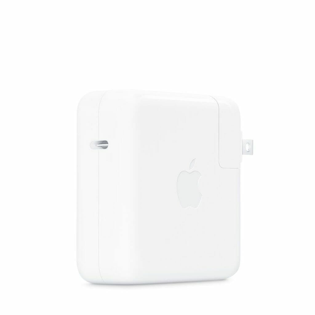
To make a board that can drive three strings of these LEDs I am going to require 3x20w + whatever the PSoC takes. A bunch. But where should I get this much power? The answer is I am going to start with a laptop Type-C charger like this one from Apple (which I have several of)
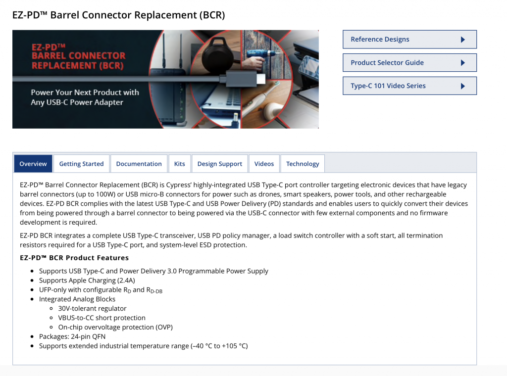
The first/next question is, how do I tell the Apple adaptor what voltage/current I want? It turns out that Cypress is the leader in Type-C chips and we make the perfect chip for this application. It is called the CYPD3177-24LQXQ and is known colloquially as the EZ-PD™ Barrel Connector Replacement (BCR). This is good because that is exactly what I want to do, replace a wall wart barrel with a Type-C.
Cypress CY4533 Development Kit
To get this going I start with the Cypress CY4533 development kit which you can see in the picture below.
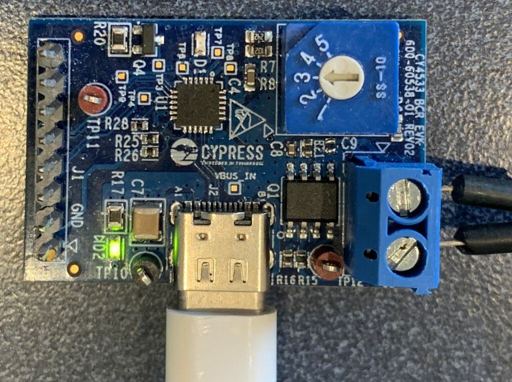
This board has
- A place to plug in Type-C
- A 5 position switch to tell the EZ-PD chip to select (5, 9,12,15 or 20V)
- Screw terminals for the output voltage
- A header with an I2C connection to the EZ-PD chip
- A load switch to isolate the load
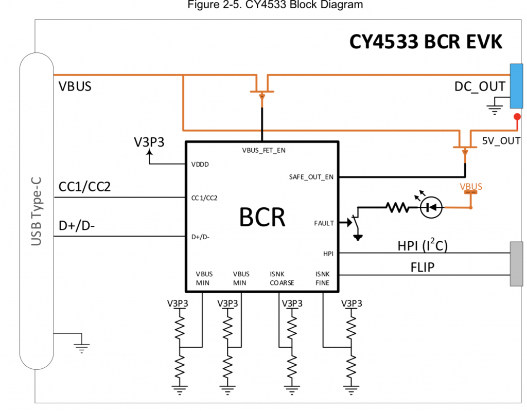
Here is a block diagram
The kit quick start guide has a picture of exactly what I did next
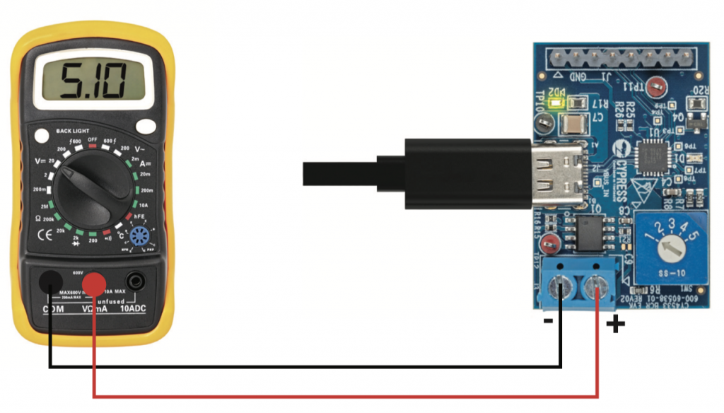
When I turned the selector, I noticed that the output from my Apple charger was (5, 9, 9, 9, 20) and wondered why. Yet, when I measured another Type-C power supply I got (5, 9, 12, 15, and 20). It turns out that when you read the fine print on the side of the charger it tells you the answer. Here is a picture of the side where unfortunately you can’t read (but I used a magnifying glass)
- 20V @ 3A = 60W
- 9V @ 3A = 27W
- 5V @ 2.4A = 12W
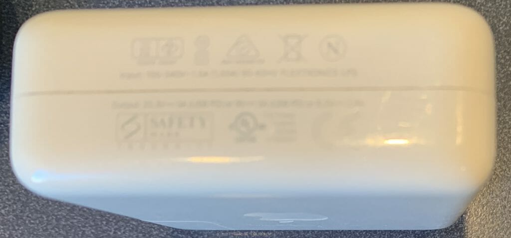
The kit guide gives you the answer as to why 5,9,9,9,20:

Infineon
OK. All that is great, but how do I power my board where I need 5V@12A + 3.6V + 3.3V + 1.8V, this is where Infineon comes into the picture. Actually, to be completely clear, Infineon came into the picture starting mid-last year when they offered to pay $10B-ish for Cypress.
Infineon makes a line of Buck regulators which are perfect for solving the first part of my problem because
- They take high-ish voltage inputs (up to 21V)
- They can supply high-ish currents at the right voltage (up to 35A)
These regulators are called the “SupIRBuck” and are part of the “Integrated POL Analog Voltage Regulators (Industrial)”
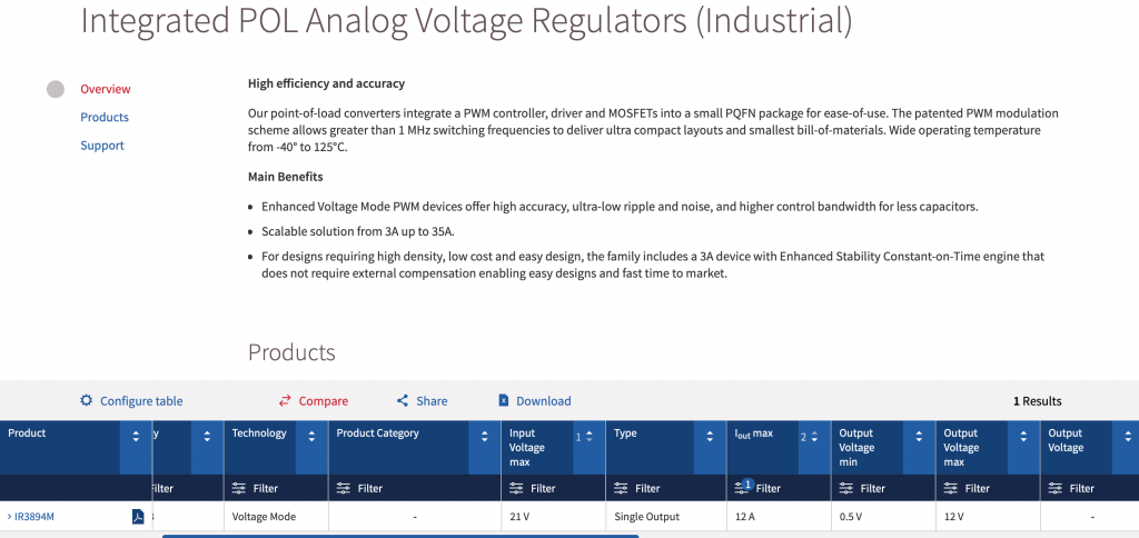
So, I ordered a development kit… unfortunately I choose the wrong one, IRDC3823 which is 12V @ 3A. However, it was close enough for me to try out.
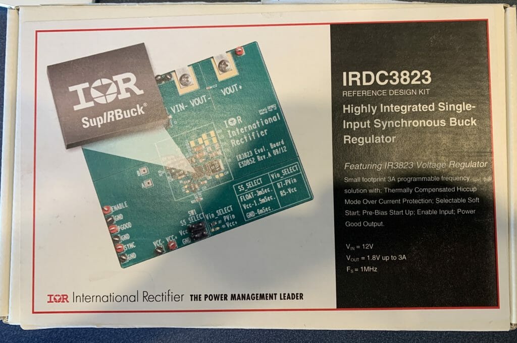
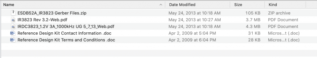
The board came in a box with the kit and a USB stick.
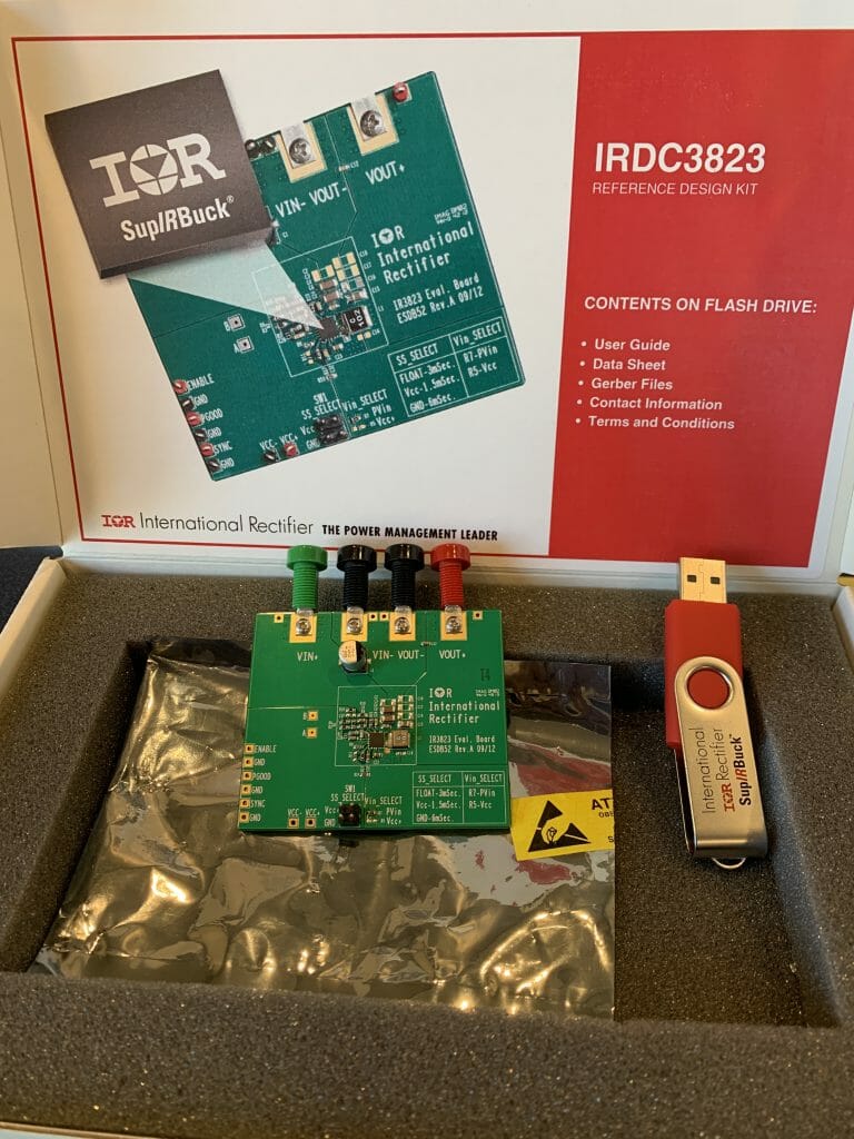
The USB Stick had the Kit Guide, Datasheet, and Gerber Files. That was nice of them.
The kit it actually very simple. It has a place to plug in your input supply (the two terminals on the left). And it has a place to plug in the output.
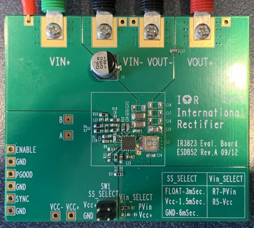
The board also has a place to configure the startup time of the Buck (the little four position jumper). When I connected the EZ-PD BCR kit to the IR3823 Eval Board, look what I got. 1.2V. Great.
This is cool and all of that… but I have a bunch of questions that need answering
- How do I get 5V out (instead of 1.2V)
- Why does the the kit guide say a maximum of 13V on the input?
- How do I configure the PGOOD signal to be compatible with the PSoC
- How do I measure the efficiency?
- What is all this stuff about switching frequency and what is the right number?
- What should I choose for SS_Select and why?
- What is an “external VCC about?
- How do I get 5A (instead of 900mA)?
- How do I talk to the EZ-PD chip via I2C?
All of these questions and more are deferred to future articles.
No comment yet, add your voice below!