PSoC 6 Introduction
#
Title
Comment
0
A Two Hour PSoC 6 Class
An introduction to the PSoC 6 class with links to all of the documents
1
Resources
Links to all of the Cypress PSoC 6 information including videos, application notes etc.
2
Your First Project
Learn how to build a PSoC 6 project and program your CY8CKIT-062-BLE development kit
3
FreeRTOS and a Debugging UART
Build a project using FreeRTOS including a debug console with the UART
4
CapSense
Build a project using the Mutual Cap Buttons and Self Cap Slider
5
Bluetooth Low Energy
Build a CapSense project using BLE and CySmart
Since I did the webinar several things have happened
- Lesson 4: I fixed an error in the stack size for FreeRTOS
- Lesson 5: The PSoC Creator BLE PDL has been upgraded to greatly simplify the notifyCapSense function
All of the projects are available at git@github.com:iotexpert/psoc-6-introduction.git or www.github.com/iotexpert/psoc-6-introduction
Project Description
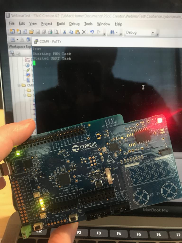
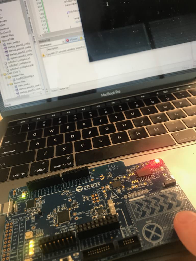
This project is a demonstration of a PSoC 6 running an RTOS using CapSense and the UART to control the intensity of the Red LED with a Pulse Width Modulator (PWM)
The CapSense will:
- BTN0 will set the intensity to 0%
- BTN1 will set the intensity to 100%
- CapSense slider will set the intensity (0-100) when touched
The UART will:
- UART Key ‘0’ turn the LED to intensity = 0%
- UART Key ‘1’ turn the LED to intensity = 100%
- UART Key ‘5’ turn the LED to intensity = 50%
- UART Key ‘?’ will printout help
How does it work?
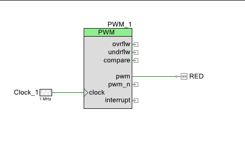
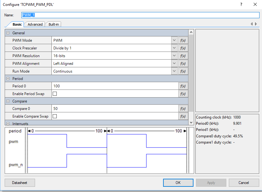
You can control the intensity of an LED with a pulse width modulator and a high frequency input clock. If the duty cycle is “small” then the intensity of the LED is low (meaning dim). If the duty cycle is “big” then the intensity is “high”. A 0% duty cycle will be off, a 50% duty cycle will be in the middle and 100% duty cycle will be all on. To make this work I will set the input clock to 1 MHz and the PWM Period to 100. The PWM Compare value will then be set between 0 and 100 to represent brightness in percent.
The Cypress CapSense block has two sensing modes, mutual capacitance and self capacitance. The CY8CKIT-062-BLE has two Mutual Capacitance buttons and a 5 segment Self or Mutual Capacitance Slider.
The project will have three tasks
- UART – Read data from the keyboard and send messages to the PWM Task
- CapSense – Read finger positions from the slider and buttons and send messages to the PWM Task
- PWM – Will have an input queue, when a integer message is received it will set the PWM compare value to the integer received (0 >= msg <= 100)
How am I going to do it?
- Create a new project by copy/paste the FreeRTOS-UART Project
- Configure Schematic for Higher Frequency Clock and Change PWM Settings
- Add a new PWM task and modify the UART
- Program and Test
- Edit the FreeRTOS.h and make a bigger heap
- Add the CapSense Buttons to the Schematic and Set the Pins
- Add the capsenseTask
- Program and Test
- Add the CapSense Slider to the Schematic and Set the Pins
- Update the capsenseTask
- Program and Test
Create a new Project by Copy/Paste of FreeRTOS-UART Project
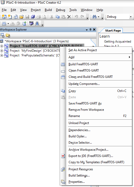
Right click on the FreeRTOS-UART Project then select “Copy”
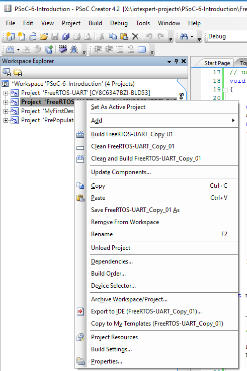
Then right click on the Workspace and select “Paste”
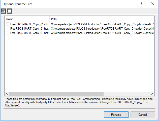
Right click on “FreeRTOS-UART-Copy01)” and rename it to “CapSense”
Click “Rename” (all of these files will be regenerated so it doesn’t really matter)
Close all windows by right clicking “Close All But This” on the start tab
Configure Schematic for Higher Frequency Clock and Change PWM Settings
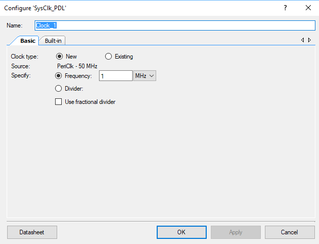
If you blink the LED fast enough, you will not be able to see the “Blink” it will just appear to be bright or dim based on the duty cycle. Start by changing the clock to 1 MHz.
Double click on the PWM_1
Fix the Period to be 100 and the compare to be 50
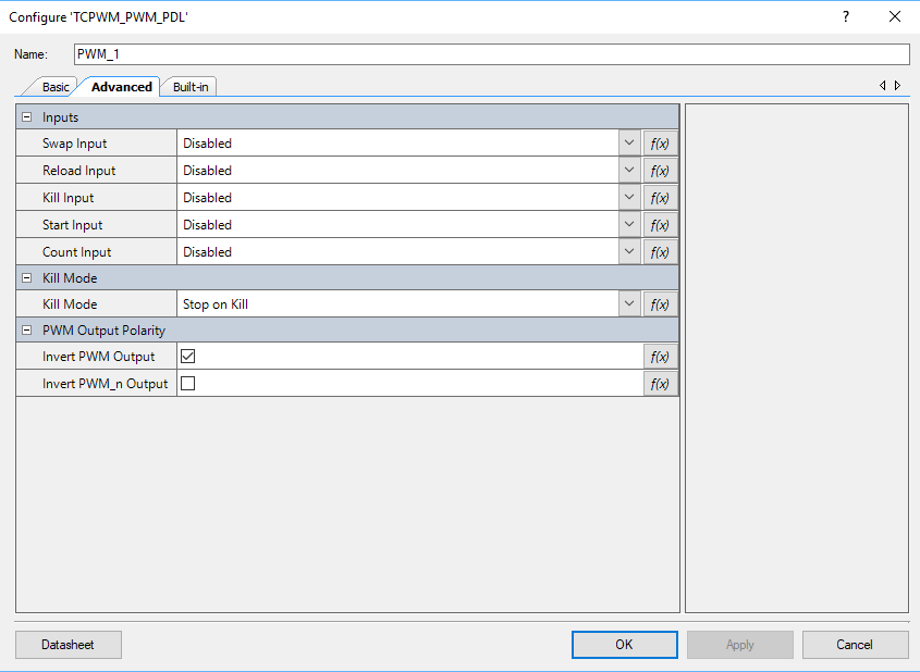
The LED on the CY8CKIT-062-BLE is active low which means that when it is 0 the LED is on. I want the opposite behavior so I can configure the PWM output to be inverted on the advanced tab. Click the button next to “Invert PWM Output”
Add a new PWM Task and Modify the UART Task
Next, I will create the pwmTask function. It will simply wait for someone to send a message to the pwmQueue. The message is simply a uint32_t that represents the PWM compare value … aka the percent intensity of the LED. When it gets the value, it will update the hardware.
Edit: In the comments below you can see that Charles asked that I clarify where these functions should go. When I did this, I put them basically at the top of the file… just under the #includes. The only thing that really matters is that they need to be put before they are used so that the compiler knows the function prototypes. If you put them after they are used then you need to make forward declarations.
#include "queue.h"
QueueHandle_t pwmQueueHandle;

// This task controls the PWM
void pwmTask(void *arg)
{
    (void)arg;

    uint32_t msg;

    printf("Starting PWM Task\r\n");
    pwmQueueHandle = xQueueCreate(1,sizeof(uint32_t));

    while(1)
    {
        xQueueReceive(pwmQueueHandle,&msg,portMAX_DELAY);
        Cy_TCPWM_PWM_SetCompare0(PWM_1_HW,PWM_1_CNT_NUM,msg);
   }
}
In the main function you need to start the pwmTask
xTaskCreate(pwmTask,"PWM Task",configMINIMAL_STACK_SIZE*8,0,3,0);
Next, I will update the uartTask
- To not getchar’s unless there is something in the RX buffer of the UART (line 13).
- Create a message aka a uin32_t based on the key pressed and send it with xQueueSend
- If there was nothing there then taskYIELD to one of the other tasks (line 35)
// uartTask - the function which handles input from the UART
void uartTask(void *arg)
{
    (void)arg;

    char c;
    uint32_t msg;

    printf("Started UART Task\r\n");
    setvbuf(stdin,0,_IONBF,0);
	while(1)
	{
		if(Cy_SCB_UART_GetNumInRxFifo(UART_1_HW))
		{
		    c = getchar();
    		switch(c)
	    	{
		    	case '0': // send the stop message
			    	msg = 0;
		    		xQueueSend(pwmQueueHandle,&msg,portMAX_DELAY);
		    	break;
		    	case '1': // Send the start message
		    		msg = 100;
		    		xQueueSend(pwmQueueHandle,&msg,portMAX_DELAY);
		    	break;
			    case '5':
				    msg = 50;
				    xQueueSend(pwmQueueHandle,&msg,portMAX_DELAY);
			    break;
			    case '?': // Print Help
				    printf("s - stop PWM\r\nS - start PWM\r\n");
			    break;
		    }
		}
		taskYIELD();
    }
}
Program and Test
Edit the FreeRTOS.h and make a bigger heap
The CapSense task is going to take more heap space that is currently allocated for FreeRTOS. To fix this I need to edit the FreeRTOS.h and change the heap size to 48K (which I picked out of the air)
#define configTOTAL_HEAP_SIZE (48*1024)
Add the CapSense Buttons to the Schematic and Set the Pins
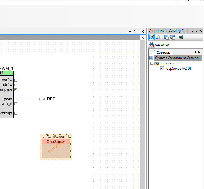
In order to add CapSense to the design, you find the CapSense component in the Component Catalog. Then you drag it into your schematic.
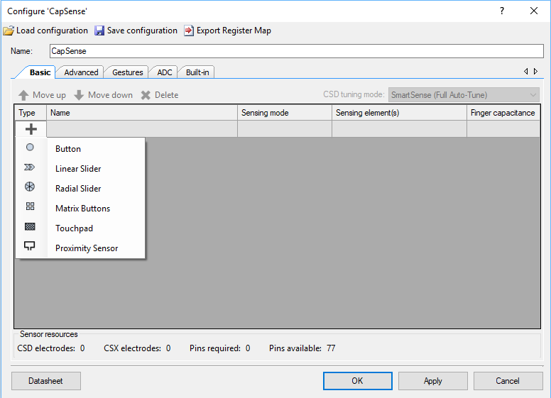
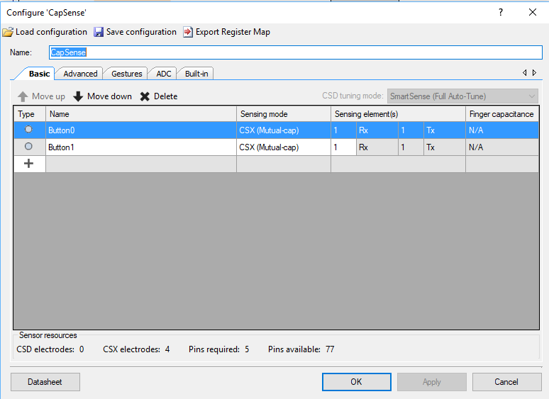
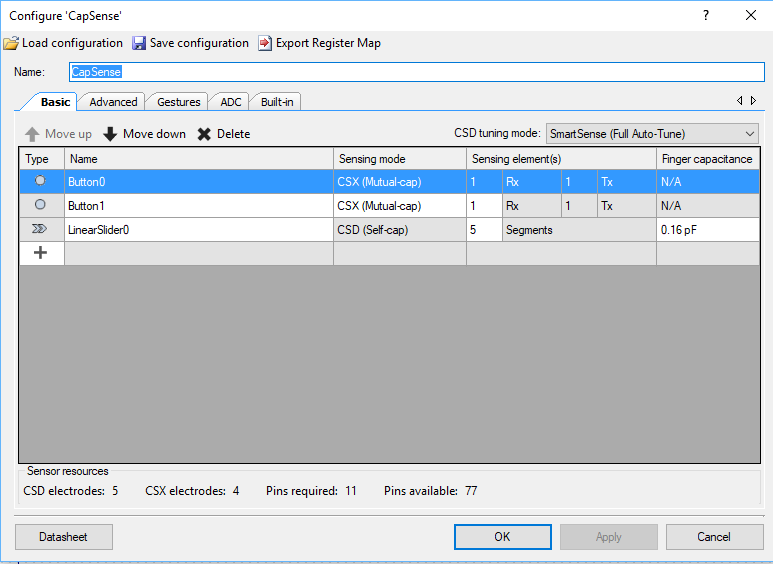
The next thing to do is configure the CapSense block. I start by re-naming it to “CapSense”. Then I click on the plus and add two “Button”s to the design.
Then I change the configuration to “CSX (Mutual-cap).
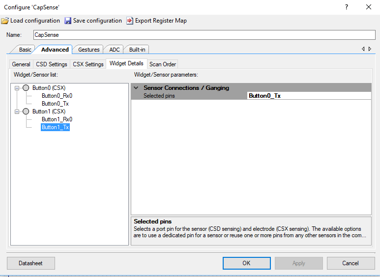
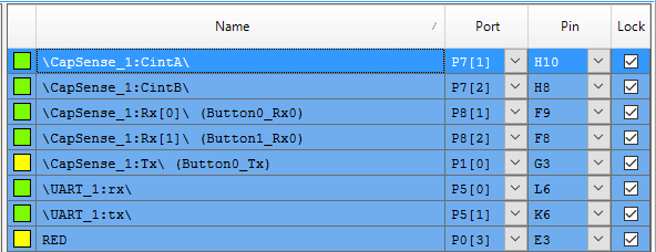
On the CY8CKIT-062-BLE, there is a shared transmit line. This saves 1 pin. You need to tell the CapSense component that you are using a shared Tx. To do this click on Advanced -> Widget Details. Then pick “Button1_tx” and set the Sensor Connection / Ganging to “Button0_Tx”
Once the CapSense is configured you need to Set the Pins.
Next you run “Generate Application” which will let PSoC Creator place and route the design plus bring in all of the required drivers.
Add the capsenseTask
Now create a new task function called capsenseTask it will
- Use 4 variables to hold the previous and current state of the buttons (line 81-84)
- Start the CapSense Block (line 88)
- Start CapSense Scanning (line 89)
- If the CapSense hardware is not busy then you can talk to it. (line 93)
- Start by turning the raw data into useable information (line 96)
- Read the state of the buttons (line 98-99)
- If the button state has changed, then send a message to the PWM Task (line 101-110)
- Save the state of the buttons (line 111-112)
- Update the baseline information (line 114)
- Start Scanning again (line 115)
- If the CapSense block is busy then yield to the other tasks (line 118)
// capsenseTask
// Read buttons and slider using CapSense and send messages to pwmQueue
void capsenseTask(void *arg)
{
    (void)arg;

    uint32_t msg;

    int b0prev=0;
    int b1prev=0;
    int b0current=0;
    int b1current=0;
    int sliderPos;

    printf("Starting CapSense Task\r\n");

    CapSense_Start();
    CapSense_ScanAllWidgets();

    for(;;)
    {
        if(!CapSense_IsBusy())
        {
            CapSense_ProcessAllWidgets();
/*
            sliderPos=CapSense_GetCentroidPos(CapSense_LINEARSLIDER0_WDGT_ID);
            if(sliderPos<0xFFFF) // If they are touching the slider then send the %
            {
                msg = sliderPos;
                xQueueSend(pwmQueueHandle,&msg,portMAX_DELAY);
            }
*/
            b0current = CapSense_IsWidgetActive(CapSense_BUTTON0_WDGT_ID);
            b1current = CapSense_IsWidgetActive(CapSense_BUTTON1_WDGT_ID);

            if(b0current && b0prev == 0) // If they pressed btn0
            {
                msg = 0;
                xQueueSend(pwmQueueHandle,&msg,portMAX_DELAY);
            }
            if( b1current && b1prev == 0) // If they pressed btn0
            {
               msg = 100;
               xQueueSend(pwmQueueHandle,&msg,portMAX_DELAY);
            }
            b0prev = b0current;
            b1prev = b1current;

            CapSense_UpdateAllBaselines();
            CapSense_ScanAllWidgets();
        }
        else
            taskYIELD();

    }
}
And start the capSense task in main.
xTaskCreate( capsenseTask, "CapSense Task",2048*2,0,3,0);
Program and Test
Add the CapSense Slider to the Schematic and Set the Pins
To make the slider work you need to add a LinearSlider widget by pressing the “+” and selecting LinearSlider
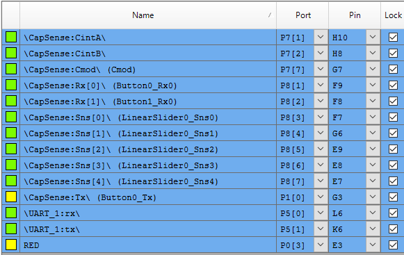
Once you have added the LinearSlider you need to set the pins for the new CapSense Slider
Update the capsenseTask to Include the Slider
The changes are small to make the LinearSlider work. You just need to
- Read the position of the slider (line 99)
- The slider will be 0xFFFF if there is no touch… in which case ignore it (line 100)
- If you got a touch, then make that a message and set it to the PWM (line 102-103)
          sliderPos=CapSense_GetCentroidPos(CapSense_LINEARSLIDER0_WDGT_ID);
            if(sliderPos<0xFFFF) // If they are touching the slider then send the %
            {
                msg = sliderPos;
                xQueueSend(pwmQueueHandle,&msg,portMAX_DELAY);
            }




6 Comments
I found a few things I had to correct (unless I missed something).
1. If the configTOTAL_HEAP_SIZE was left as the 10240, the Capsense task would fail to start and return a -1 code, indicative of not enough memory.
2. With the heap set higher (I took your 48*1024) from the webinar, the capsense would start, but since the task creation priorities were 3 for the PWM and Capsense but only 1 for the UART task, it would not start (at least to the printf) until I changed the taskYIELD to a vTaskDelay(1), or changed the UART priority to the 3 as well to let the pre-emptive scheduler work things out.
Otherwise the webinar was great, informative and entertaining. Thanks very much.
1- Yes you are right… if it had stayed at 10240 (which for some reason is the PSoC Creator default it wouldn’t work. I notice above that I “say” to make it (48*1024) which I just picked out of the air.
2- Yes you are right. If you look in the workspace on git hub I have the CapSense project priorities all set at 3… which means that when I made that workspace I didn’t copy/paste as I showed in the demo.
Personally I think having their priority all set to (3) is the best way.
Thank you for the clarifications and I am glad you enjoyed the event.
For the section “Add a new PWM Task and Modify the UART Task”, the section is not explicit in saying where you are supposed to put the subsequent code.
I made an edit to show where. Thanks for the comment
FYI for those trying to duplicate what Alan is doing, if you run the UART task as shown above, you’ll notice that two case statements are missing for “s” and “S” to start and stop the PWM. Just add them (from Lesson 3) for completeness if you wish.
Thanks… good catch. Ill fix it.
Alan