Summary
Recently I have been working on RTOSs. While I was completing the port of FreeRTOS, I ran into something that I just didn’t understand. So, I called a close friend who is a remarkable programmer. Instead of telling me the answer, he said “I could tell you, or you could set a breakpoint on the reset vector and find out for yourself”. This simple statement sent me into weeks of single stepping ARM assembly language, reading linker scripts, reading application notes and crawling through boot source code to figure out what is really happening during the PSoC4 Boot Sequence.
So, what happens when power is applied to a PSoC4? I suppose that I could tell you to “Set a breakpoint on the reset vector and find out for yourself.” Which would be a good thing for you to do, but it would’nt make for very interesting reading. It also wouldn’t tell the whole story as what I am going to show you is what happens after the initial supervisory part of the boot occurs.
In this series posts I will take you through the process.
- Using the debugger: Setting a breakpoint on the reset vector of PSoC4 Boot Sequence
- Creating the Exception Table using the Linker
- Generated Source & cy_boot & Cm0Start.c
- RAM Vectors –> RAM Vectors
- Start_c
- initialize_psoc
- Solving the mystery of __libc_init_array & a GCC trick
The whole process relies heavily on the linker script to get all of the code and vectors into the right place. If you have never dug through a linker script, it can be a bit overwhelming, but don’t despair as I will explain the parts required to make this work.
All that being said, the PSoC4 Boot Sequence must:
- Move the Flash based exception vector table to the RAM (so that it can be changed)
- Startup the C Standard library environment
- Initialize the C-variables (from the Data segment) and zero the ones in the BSS segment.
- Move the table of PSoC flash based register settings into the appropriate volatile latches (make the PSoC a PSoC)
Using the debugger: Setting a breakpoint in the reset vector of PSoC4 Boot Sequence
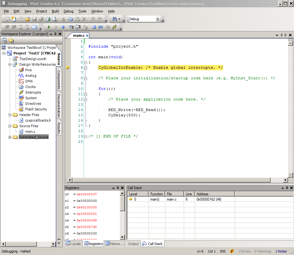
The first thing that I did was create a blank PSoC4 M project with a blinking LED. I then clicked the debug button which built the project, programmed it into the board, then started the debugger. When you do that, here is what you will see. You can see that the debugger by default boots the chip and runs until the first line in main (which is beyond the reset vector)
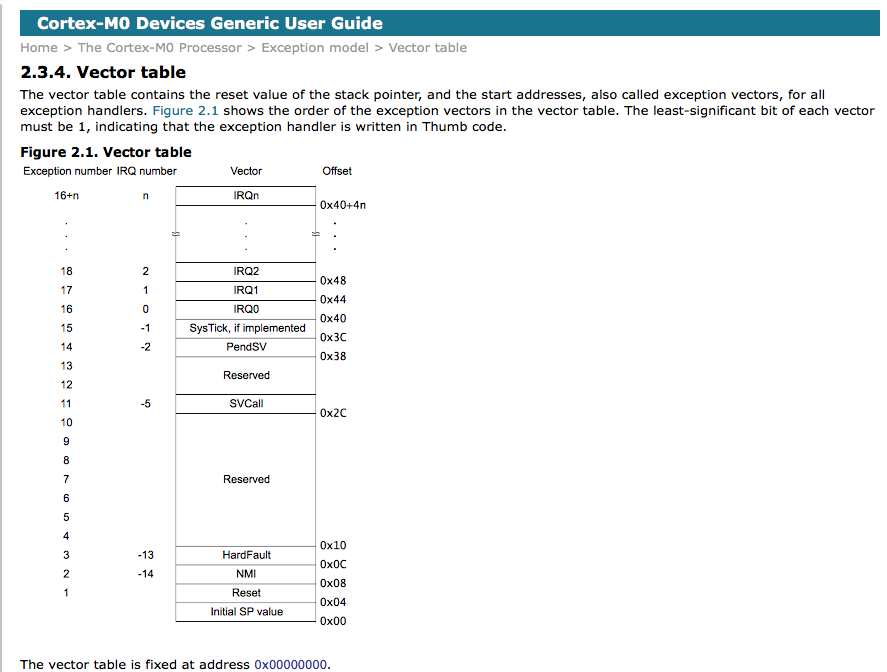
But I want to break on the reset the vector. I didn’t even know what function Cypress had setup for the reset vector or exactly where to look for it. I knew that I needed to figure out where the reset vector is located in the CM0 so that I could put a breakpoint on that location. Start by googling “arm cortex m0 reset vector” The first google hit is an ARM page that shows the layout of all of the exception vectors:
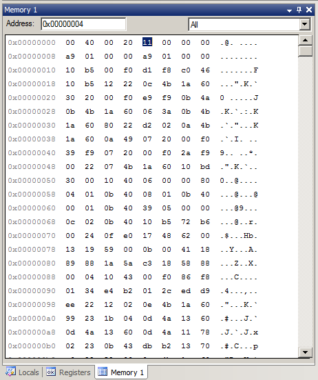
The reset vector is at address 0x04. Now examine the memory in the debugger to find the address (which you can see is 0x00000011 – don’t forget that this processor is little endian). You can examine the memory by clicking the “Memory 1” tab at the bottom of the debugger.
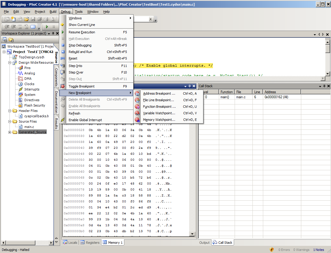
Create an address based breakpoint by using the debug->New Breakpoint menu.
Then press the reset button (which I highlighted in Red) on the debugger. This will cause a reset of the chip, the PSoC4 ARM Cortex-M0 will load the program counter (PC) and start running. You will end up on a screen that looks like this:
That is a pretty convenient place to stop. The function is called “Reset” which makes good sense, and it is in a file called “Cm0Start.c”. When I saw this, I thought that the whole exercise was going to be a cakewalk, little did I know that I was about to fall into a rabbit hole, that was going to take a few weeks to descend out of.
In the next post I will show you where the reset vector came from and how it and stack pointer got into the flash.
Article
Description
PSoC4 Boot Sequence (Part 1) - Debugging to the Reset Vector
An introduction to the PSoC4 Boot Sequence
PSoC4 Boot Sequence (Part 2) - Creating the Exception Table using the Linker
Building the exception vector table
PSoC4 Boot Sequence (Part 3) - Preinitializing Variables before main()
Initializing BSS and Data
PSoC4 Boot Sequence (Part 4) - Linker trickery with __attribute_((constructor(101)))
Running initialize_psoc()
PSoC4 Boot Sequence (Part 5) - Initialize PSoC
4 Comments
Hello!
I try to make the same as in your article, but when I try to set “Address Breakpoint” to 0x00000004 I get message like “it not possible to set hardware breakpoint set software breakpoint”. I wasn’t able to catch program at Reset in Cm0Start.c.
I can catch my program only at InputInterrupt_StartEx(SWPin_Control) line.
Code example: Digital_Pins01
Device: CY8C4245AXI-483
Thanks!
You need to put the breakpoint on the address contained in the reset vector… the debugger won’t break until it try’s to load an instruction from that address. I fell into this as well. The loading of the reset vector into the PC doesn’t trigger a break. The break occurs when it fetches that opcode.
Thank You! Now it works. I’ve put 0x00000004 in Address Breakpoint, but correct address is 0x00000011.
Excellent!