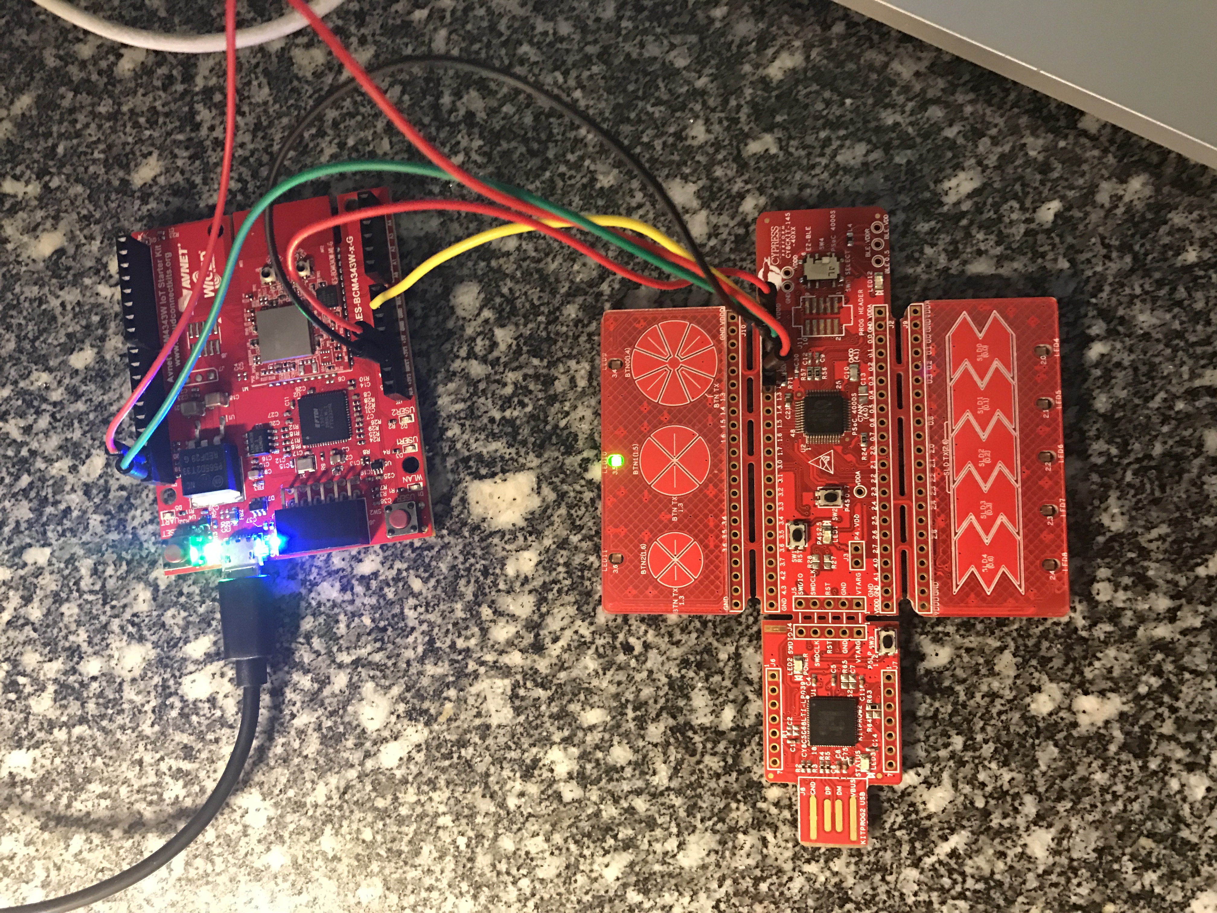
I finally made it to Munich late yesterday afternoon… then I proceeded to turn my hotel room into an electronics lab as I frantically worked to finish everything for tomorrow. Earlier this year I wrote a whole series of posts about the PSoC4000S & CY8CKIT-145 after the Embedded World show. We finally have volume production on the development kit and will be giving them out at the show this week. So, I decided to use the -145 as part of the user interface for my Electronica project. The devkit functions as the block labeled “PSoC Capsense”. The wire between the “PSoC Capsense” and the “WICED WiFi” will be I2C (the green and red wire from the picture below)
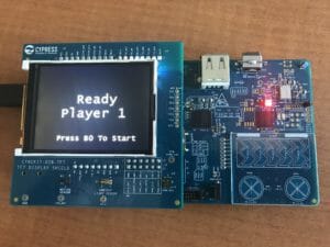
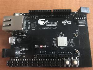
The -145 devkit has the PSoC4000S silicon on it which has the new mutual capacitance capsense block. On the devkit, there are three mutual cap buttons and one slider. Here is a picture of the devkit connected to the WICED WiFi board that I am going to use:
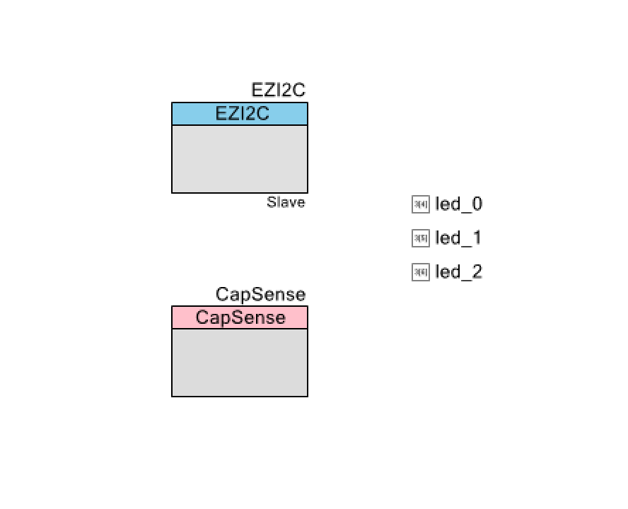
I want to make as simple of a PSoC Creator project as I can possibly do as I want to be able to easily do it live. Here it is:
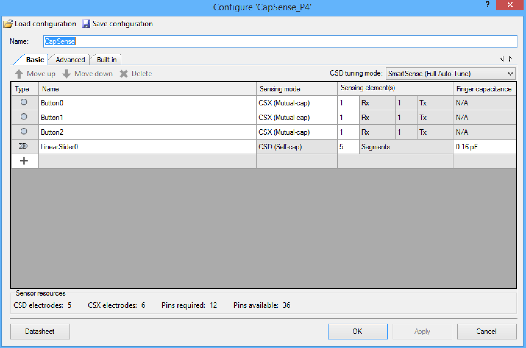
The CapSense block is configured with three mutual cap buttons and 1 self-cap slider:
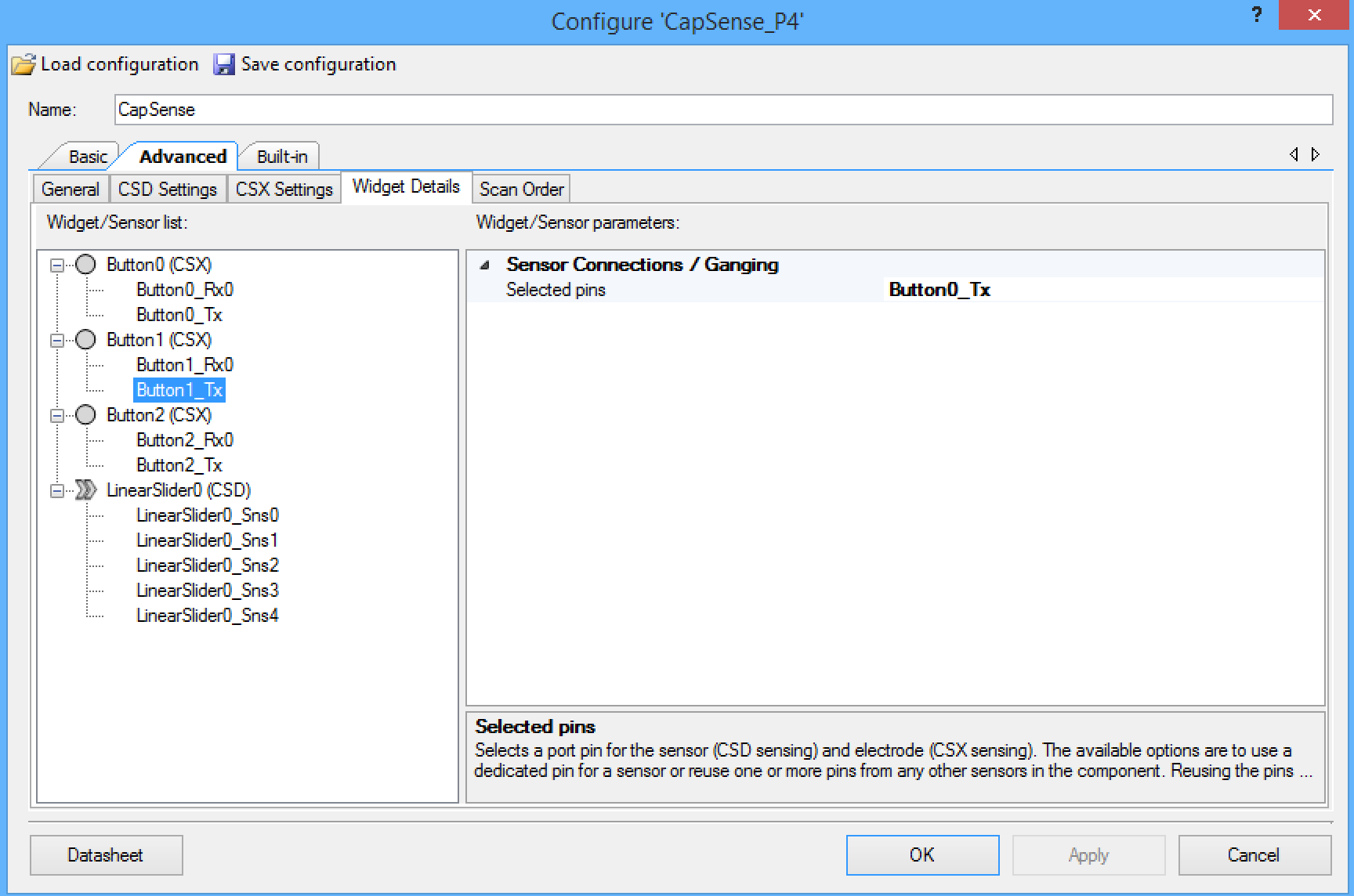
On this development board, the three mutual cap buttons share the same transmit line, so you need to configure the component that way. The screen shot below shows the configuration of the “Button1_Tx” which is set to share the “Button0_Tx”. You need to make the same setting for “Button2_Tx”.
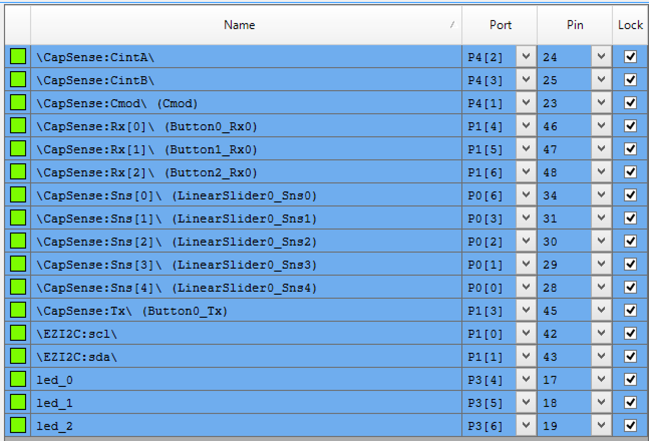
The next step is to assign all of the pins to the proper locations:
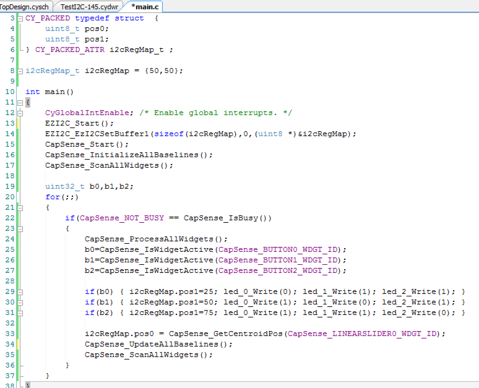
Finally the smallest amount of firmware that I could think up to hold it all together.
Line 3-6: define a structure that the WICED board will be able to read. It will represent the position of two of the Servo motors. The CY_PACKED provides the compiler appropriate key words to make the bytes be right next to each other in the RAM, i.e. not word aligned..
Line 8: initializes both positions to 50%.
Lines 12-17 get the components going
Line 22: Checks to make sure that the CapSense block is not scanning before it reads the results
Line 24: Tells the CapSense block to process the results from the previous scan
Lines 25-31: Looks at the three buttons, sets the LEDs and sets pos1 to be either 25%, 50% or 75%
Line 33: Reads the position of the slider and assigns it to “pos0”
Lines 34-35: Gets the scanning going again
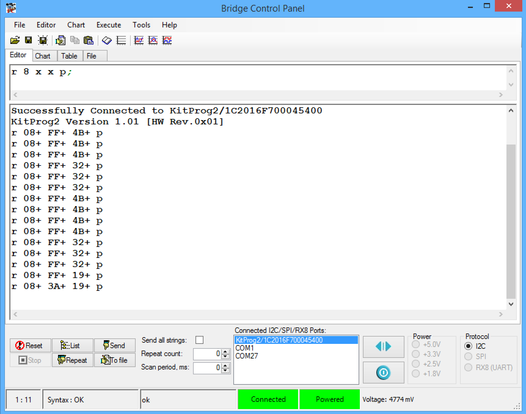
To test the system I first used the bridge control panel. First, connect to the kitprog2. Then I setup a read from the I2C address (0x08) which is the address of my board. I then click repeat which runs the read command over and over again. In the picture below you can see that I tested the three position of the button (25,50 and 75 which are also known as 0x19, 0x32 and 0x4B). Then I tested the slider by touching it about in the middle (0x3A)
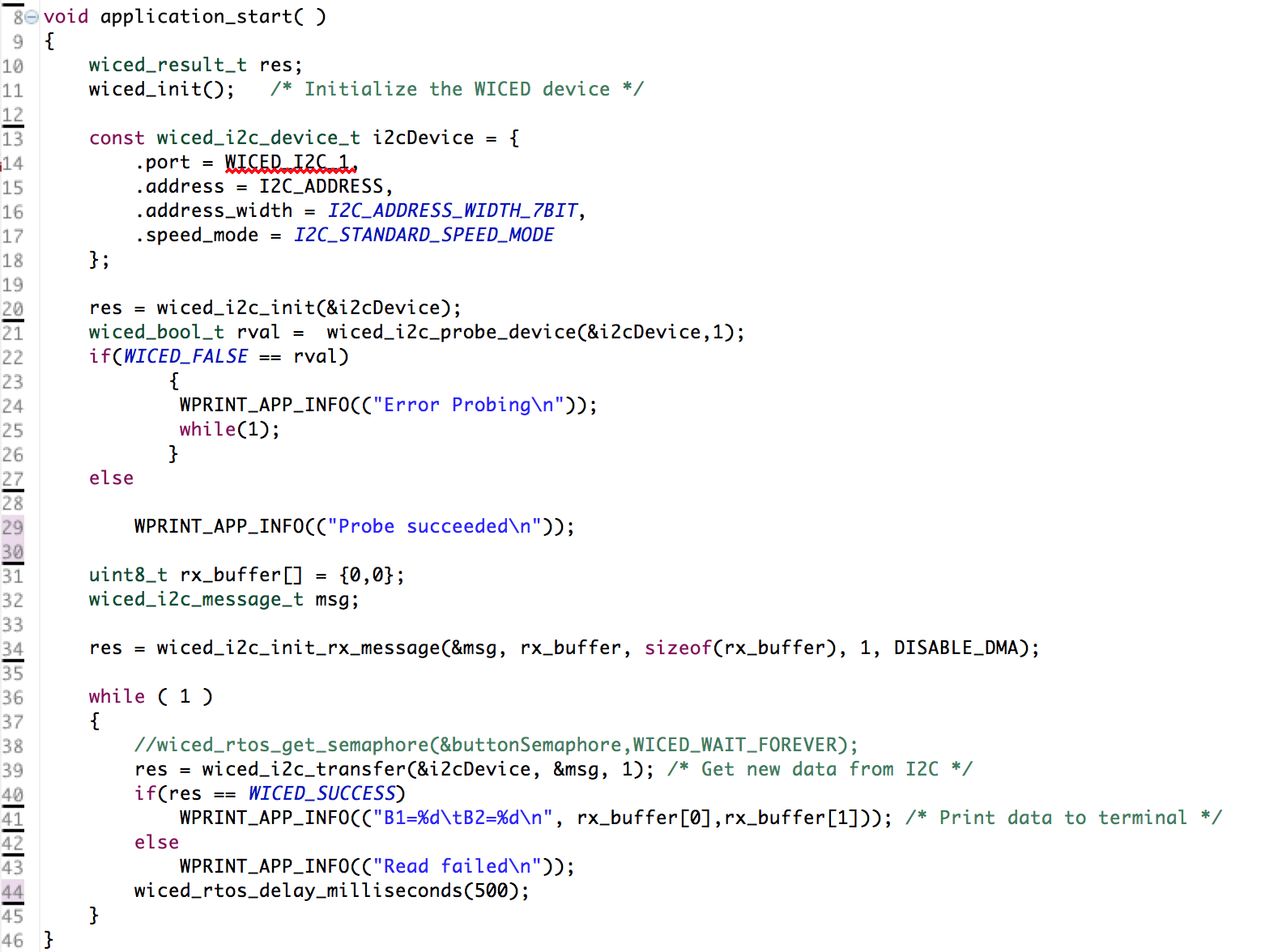
The next thing to do was make sure that the WICED devkit could read my I2C slave, so I wrote some WICED firmware to read the I2C registers every 500ms:
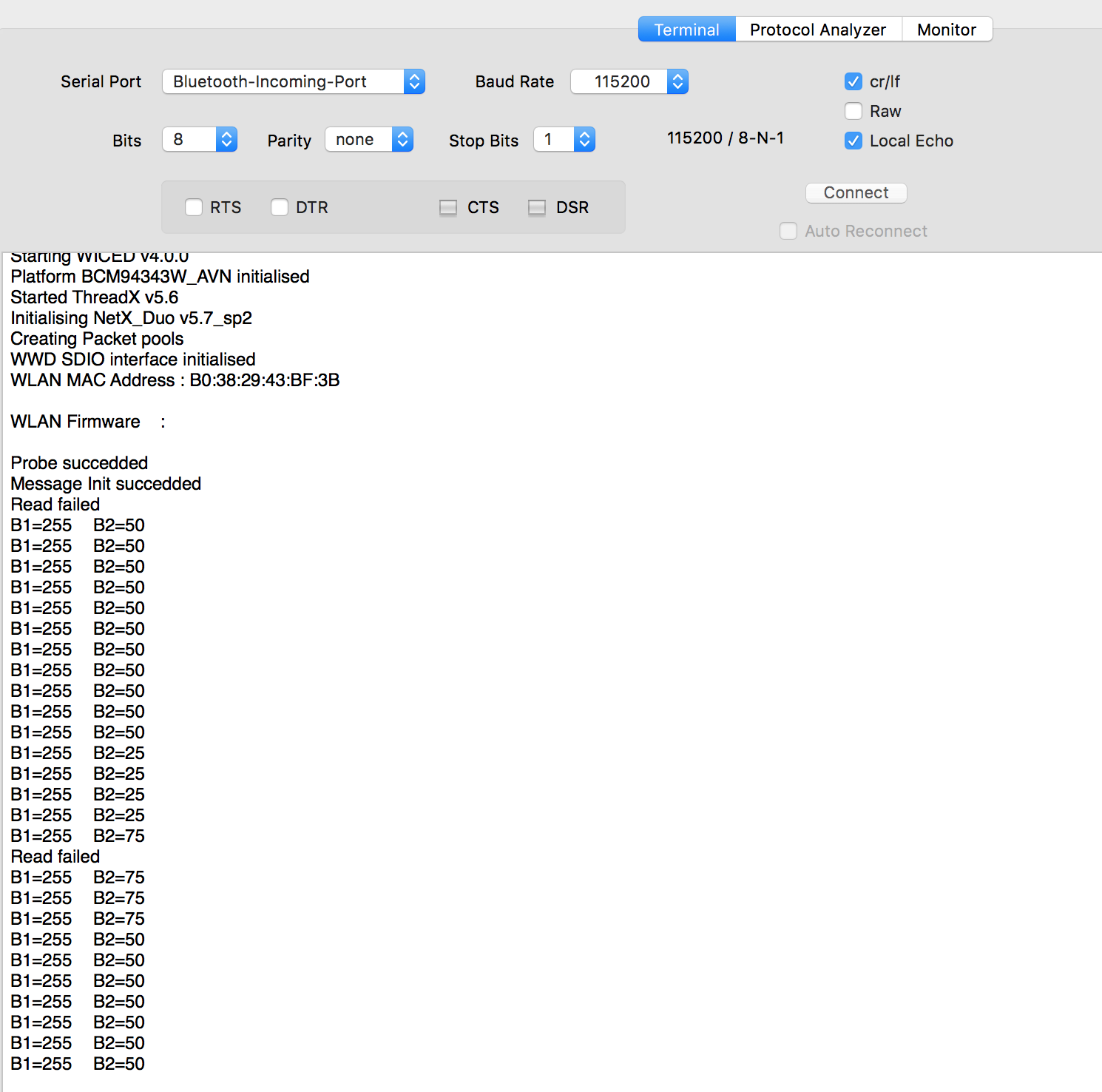
But, occasionally I was getting a “read failed”:
Last night in my sleep deprived state I was struggling like crazy to figure it out. This morning after some sleep I realized that the WICED board that I have must not like getting its I2C clock stretched. So, I changed the priority of the I2C interrupt on the PSoC and that fixed the problem:
Keep watching here for more updates on the project.


No comment yet, add your voice below!