Cypress introduced it’s first mass market microcontroller in 2001. It used a Cypress designed 8 bit CISC processor running at 24 MHz, with as little as 4 KB Flash and 256 bytes RAM. Wrapped around that was a neat array of programmable analog and digital blocks. This may not sound like much, but with a creative mindset you could get these parts to do amazing things. For instance, I once implemented a complete ultrasonic ranging sensor with full wave analog demodulation in a single PSOC1 as shown below.

With CPU resources at a premium, you had to write tight, efficient code to get the most out of PSOC1. A single C library could consume the entire Flash. Consequently, I wrote a lot of assembly code. That’s not so bad, since I actually enjoy it more than C. There’s a certain elegance to well written, fully commented machine code. In the case of PSOC1, here’s what you had to work with: 5 registers, some RAM and Flash. That’s it. Real Men Write In Assembly.
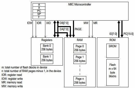
We’ll start with simple machine code instruction to make the CPU do something. You can reference the M8C assembly language user guide here for more details. To get the M8C to execute 2+3=5 we write:
mov A,2 ;Load A with 2
add A,3 ;Add 3 to A. Result=5 is in A
We can get fancy by using variables. Let’s add R=P+Q. Assume P is at RAM location 0x20 and Q is at location 0x21, and R is at 0x22
;Initialize variables
mov [0x20],2 ;Load P with 2
mov [0x21],3 ;Load Q with 3
;Add variables
mov X,[0x20] ;X <- P
mov A,[0x21] ;A <- Q
adc [X],A ;X <- P + Q
mov [0x22],X ;R <- X
The fun thing about assembly is you can always dream up cool ways of doing things in less operations based on the machine’s instruction set. For example, we can simplify the above code as follows:
;Add variables
mov [0x20],[0x22] ;R <- P
adc [0x22],[0x21] ;R <- P + Q
In my experience, a good programmer with expert knowledge of the instruction set and CPU resources can always write better code than a compiler. There’s a certain human creativity that algorithms can’t match.
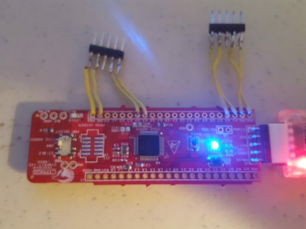
All that being said, I had not seen a good “machine code 101” tutorial for writing assembly in PSOC Creator on modern ARM M0 processors. So let’s walk through one now. We’ll use a CY8CKIT-145 and blink the LED. It’s just what happens to be laying around on the lab bench. Any PSOC4 kit will do.

We’ll start by creating a standard project in PSOC Creator, drop a Digital Output pin on the schematic and call it “LED”
Then open the .CYDWR file and drag pin LED to P2[5], since that’s where it is on the LED board. Yours may be in a different place on whatever board you are using.
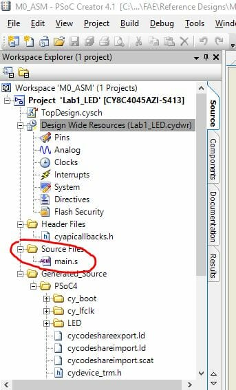
Now under “Source Files” in the workspace directory you will delete main.c and replace with main.s
Now right clock on “Source Files”, select “Add New File” and select “GNU ARM Assembly File” in the dialog. Rename the file from GNUArmAssembly01.s to main.s
Your workspace ends up looking like this:
So far, so good. Now open main.s, delete everything if it’s not empty and add the following code. This sets up the IDE for M0 assembly architecture
// ==============================================
// ARM M0 Assembly Tutorial
//
// 01 – Blink LED
// ==============================================
.syntax unified
.text
.thumb
Next we need to include register definitions for the chip we are using. These are all from the PSOC4 Technical Reference Manual (TRM)
// ==============================================
// Includes
// ==============================================
.include “cydevicegnu_trm.inc”
Then we are going to do some .equ statements, same as #define in C. This identifies the Port 2 GPIO data register plus bits for the LED pin in on and off state
// ==============================================
// Defines
// ==============================================
.equ LED_DR,CYREG_GPIO_PRT2_DR // LED data reg address
.equ LED_PIN,5 // P2.5
.equ LED_OFF,1<<led_pin // 0010 0000
.equ LED_ON,~LED_OFF // 1101 1111
Now you add the right syntax to set up main()
// ==============================================
// main
// ==============================================
.global main
.func main, main
.type main, %function
.thumb_func
Finally we add the code for main, which is pretty simple:
main:
ldr r5,=LED_DR // Load GPIO port addr to r5
loop0:
ldr r6,=LED_ON // Move led data to r6
str r6,[r5] // Write r6 data to r5 addr
ldr r0,=0xFFFFFF // Argument passed in r0
bl CyDelayCycles // Delay for N cycles
ldr r6,=LED_OFF // Move led data to r6
str r6,[r5] // Write r6 data to r5 addr
ldr r0,=0xFFFFFF // Argument passed in r0
bl CyDelayCycles // Delay for N cycles
b loop0 // Branch loop0
.endfunc // End of main
.end // End of code
One thing to note: The function CyDelayCycles is defined CyBootAsmGnu.s. Any function in assembly gets its arguments passed by the first 4 registers r0,r1,r2 and r3. Before calling the function you simply load r0 with the argument then do a bl (branch with link). This is also why I avoided the first 4 registers when messing with LED data. If you’re interested in doing more with ARM assembly, definitely read the Cortex M0+ Technical Reference Manual. It’s a great primer for the M0+ instruction set.
That’s it. End result is a blinking LED. Cool thing is you can use PSOC Creator with all it’s nice features, but sill access the power of machine code.
You can get the project ZIP file here.
Regards
Darrin Vallis




6 Comments
Many thanks for this informative and graphical tutorial.
I would like to ask about the exact nature of the ‘step-function’ decorated Op-Amp – is that by any chance a Schmitt-Trigger?
It actually seems in your diagram to convert Amplitude to width of a square signal, rather not to cap a sine wavelength.
That step function is just a comparator.
Alan
p.s. Sorry for the VERY slow response.
FYI Cypress app note AN89610 shows how to embed Cortex assembler in C source code. It also discusses other issues regarding Cortex assembler.
Mark… that is an excellent document.
“Real Men Write In Assembly” but
I have been told “Real Men Never Make Women Cry”
I think that it would be best for me not to wade into Men&Women in this forum… I like to stick to the realm of knowable stuff 🙂