PSoC 6 SDK OneWire Bus (Part 3): Remove Busy Wait & Debug

Summary

In this article I will replace the stupid busy wait implementation of OneWire write and read bit with an interrupt based implementation.

Story

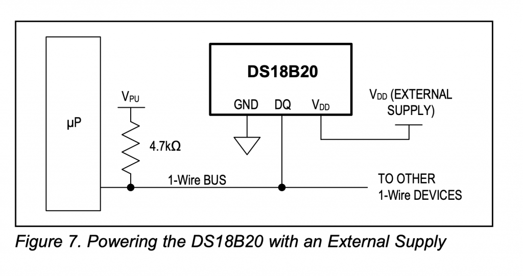
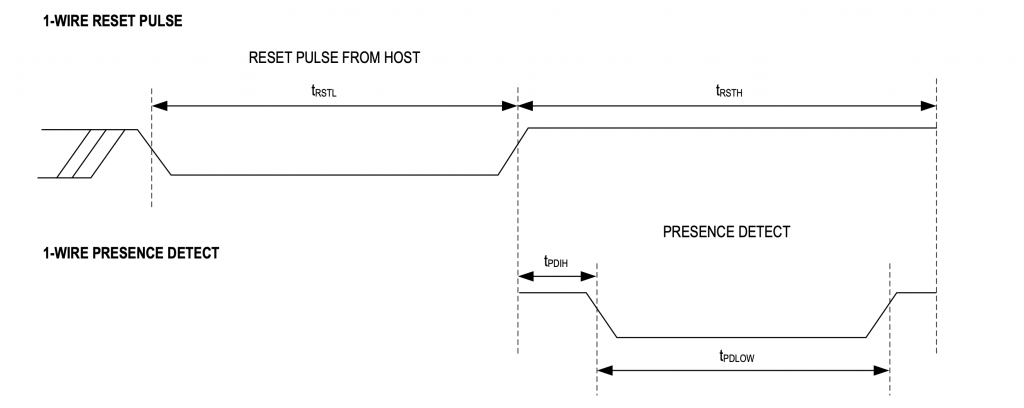
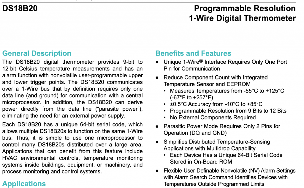
In the previous article, I implemented a OneWire bus library for PSoC 6.  Specifically, to read temperatures from the DS18B20 1-wire temperature sensor.  This implementation used the CyDelay to handle bit timing. Here is the write bit function.

owb_ret_t owb_write_bit(OneWireBus *bus,uint8_t val)
{
    owb_ret_t rval = OWB_STATUS_OK;

    cyhal_gpio_write(bus->pin,0);
    if(val == 0)
    {
        CyDelayUs(60);
        cyhal_gpio_write(bus->pin,1);
        CyDelayUs(2);
    }
    else
    {
        CyDelayUs(1);
        cyhal_gpio_write(bus->pin,1);
        CyDelayUs(60);
    }
    return rval;
}

And the read bit function.

owb_ret_t owb_read_bit( OneWireBus *bus, uint8_t *bit)
{
    owb_ret_t rval = OWB_STATUS_OK;

    cyhal_gpio_write(bus->pin,0);
    CyDelayUs(1);
    cyhal_gpio_write(bus->pin,1);
    CyDelayUs(5);

    *bit = cyhal_gpio_read(bus->pin);
    CyDelayUs(60);
    return rval;
}

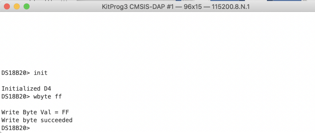
Both of these functions APPEAR to work perfectly.  Here is a write of 0xFF

However, both of these implementations are subject to fail if an interrupt from the RTOS occurs during the delay period.  You could easily end up with a delay that is too long by enough that the sensor attached to the bus won’t work.  Moreover, I have always hated busy wait loops as the processor could be doing something useful.  So let’s replace this with something better.

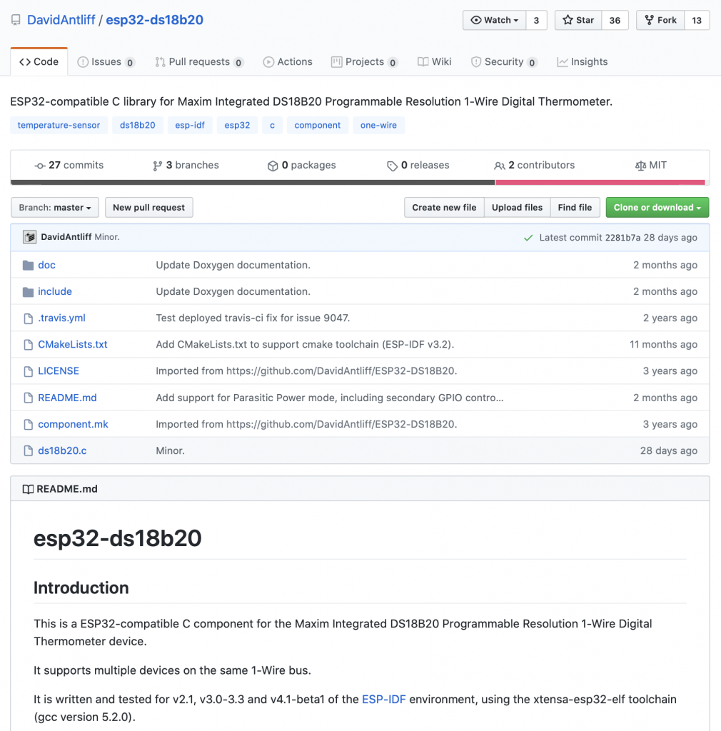
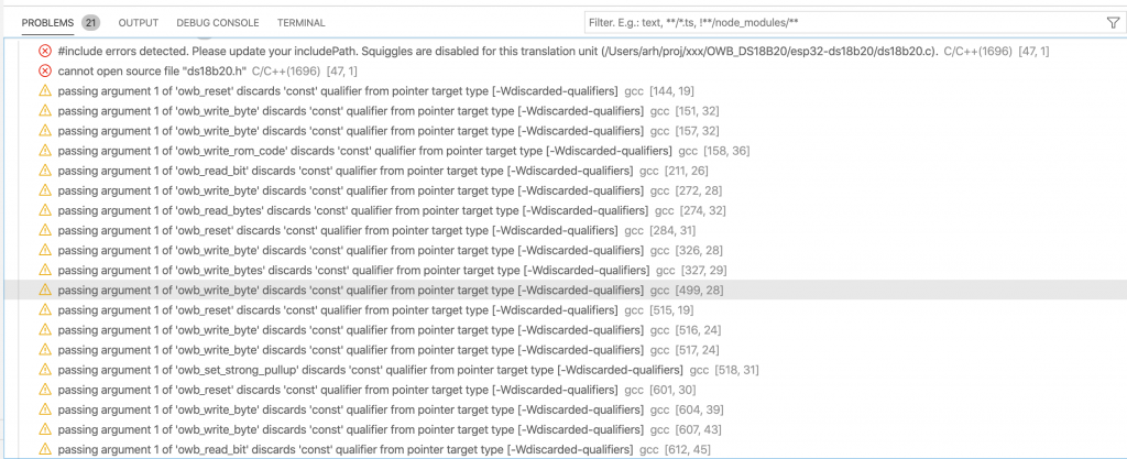
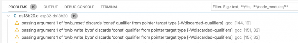
This is a late edit to the article, but as I read the documentation for the “owb” library I found this note in Dave Antliff’s documentation

Im not exactly sure what a “RMT” is in the world of ESP32, but I gotta imagine that it is a hardware timer.

Implement an HW Timer and Interrupt Scheme

Both the read and write operation require that the master

  • Write a 0
  • Wait for some time
  • Write a 1
  • Wait for some time (then optionally read)
  • Wait for some time end

The PSoC 6 TCPWM can be used to generate accurate interrupts at specific times in the future.   This hardware is abstracted using the Cypress HAL which will let you configure

  • The input frequency to the timer
  • The counter in the timer
  • A “compare” value to trigger an interrupt with event type CYHAL_TIMER_IRQ_CAPTURE_COMPARE
  • A “period” value to trigger an interrupt with the event type CYHAL_TIMER_IRQ_TERMINAL_COUNT

If you are confused about the TCPWM hardware you are not alone, it can do a mind blowing amount of different things.  However in this simple case we have it set to

  1. Input frequency 1 Mhz (aka 1uS per count)
  2. Start at 0
  3. Trigger an event CYHAL_TIMER_IRQ_CAPTURE_COMPARE at the compare value
  4. Tigger an event CYHAL_TIMER_IRQ_TERMINAL_COUNT at the period
  5. Stop counting
  6. Reset back to 0

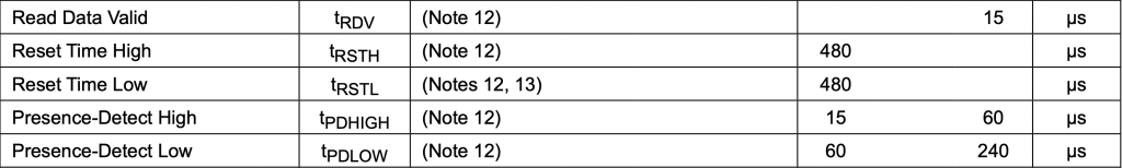
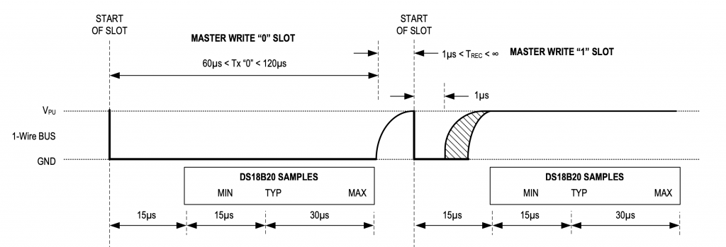
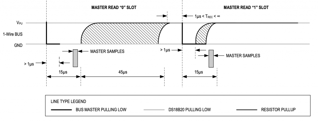
If you look the code below on lines 23-30 the configuration of the timer is set.  Remember from the data sheet that a “1” is a 1uS 0 followed by a 60uS 1 and a 0 is a 60uS 0 followed by a 1uS 1.  I use the “compare” to be the trigger from 0–>1.  Notice lines 5-9 in the code below.

On lines 40-41 I tell the HAL that I am interested in getting an event interrupt.

Line 43 initiates the write with a write of 0.  Then line 45 starts the timer going.

To “end” the operation I use a semaphore to wait until the interrupt is triggered by the Terminal Count (aka Period).

void write_bit_event_callback(void *callback_arg, cyhal_timer_event_t event)
{
    OneWireBus *bus = (OneWireBus *)callback_arg;

    if(event & CYHAL_TIMER_IRQ_CAPTURE_COMPARE)
    {
        cyhal_gpio_write(bus->pin,1);
    }
    if(event & CYHAL_TIMER_IRQ_TERMINAL_COUNT)
    {
        BaseType_t xHigherPriorityTaskWoken;
        xHigherPriorityTaskWoken = pdFALSE;
        xSemaphoreGiveFromISR(bus->signalSemaphore,&xHigherPriorityTaskWoken);
        portYIELD_FROM_ISR( xHigherPriorityTaskWoken );
    }

}

owb_ret_t owb_write_bit(OneWireBus *bus,uint8_t val)
{
    owb_ret_t rval;

    cyhal_timer_cfg_t cfgBit = {
        .is_continuous = false,
        .direction = CYHAL_TIMER_DIR_UP,
        .is_compare = true,
        .compare_value = 1,
        .period = 70,
        .value = 0,
    };

    if(val == 0)
        cfgBit.compare_value = 65;
    else
        cfgBit.compare_value = 1;
    
    cyhal_timer_configure(&bus->bitTimer,&cfgBit);
    cyhal_timer_reset(&bus->bitTimer);

    cyhal_timer_register_callback(&bus->bitTimer,write_bit_event_callback,bus);
    cyhal_timer_enable_event(&bus->bitTimer,CYHAL_TIMER_IRQ_TERMINAL_COUNT|CYHAL_TIMER_IRQ_CAPTURE_COMPARE,5,true);

    cyhal_gpio_write(bus->pin,0);

    cyhal_timer_start(&bus->bitTimer);
    
    BaseType_t rsem = xSemaphoreTake(bus->signalSemaphore,1); 

    if(rsem == pdTRUE)
        rval = OWB_STATUS_OK;
    else
        rval = OWB_STATUS_ERROR;

    return rval;
}

Fixing the Write Bug

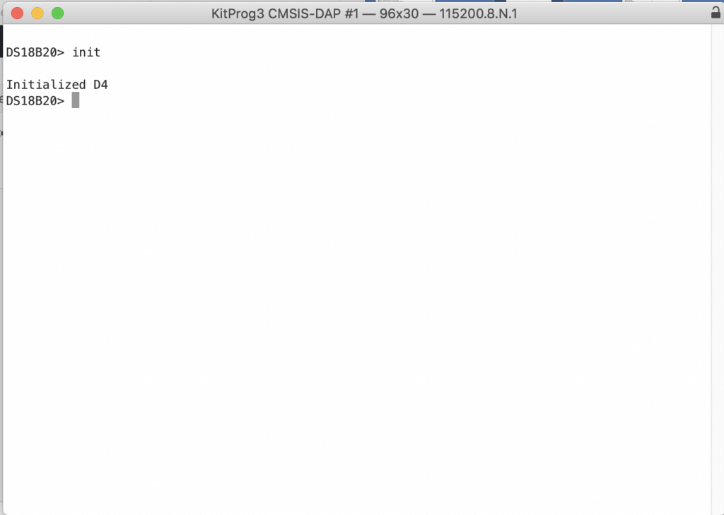
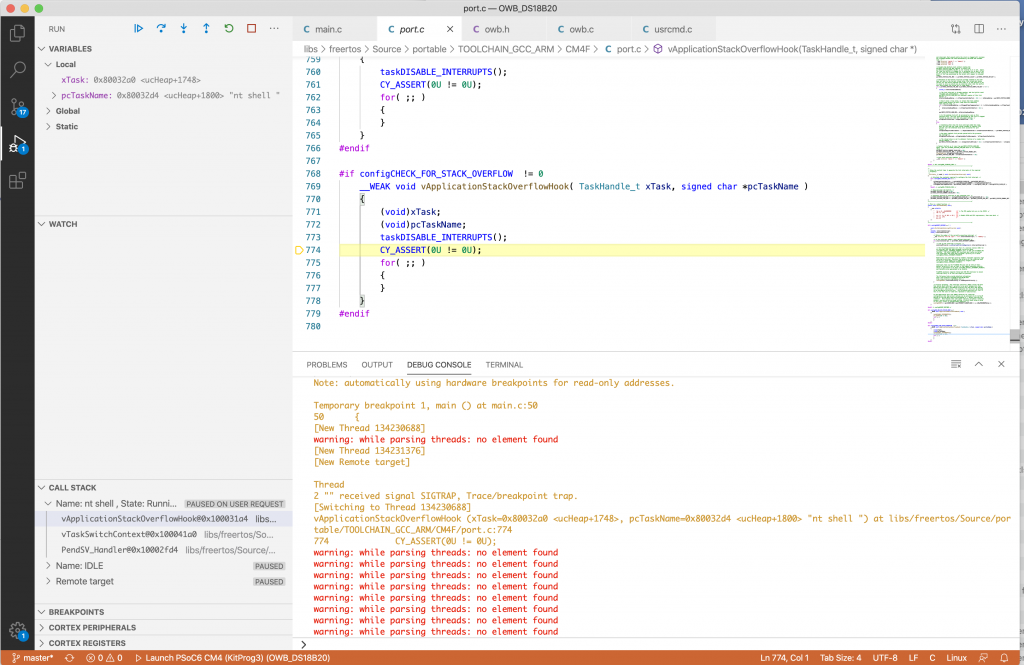
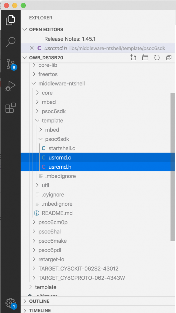
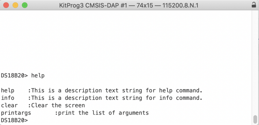
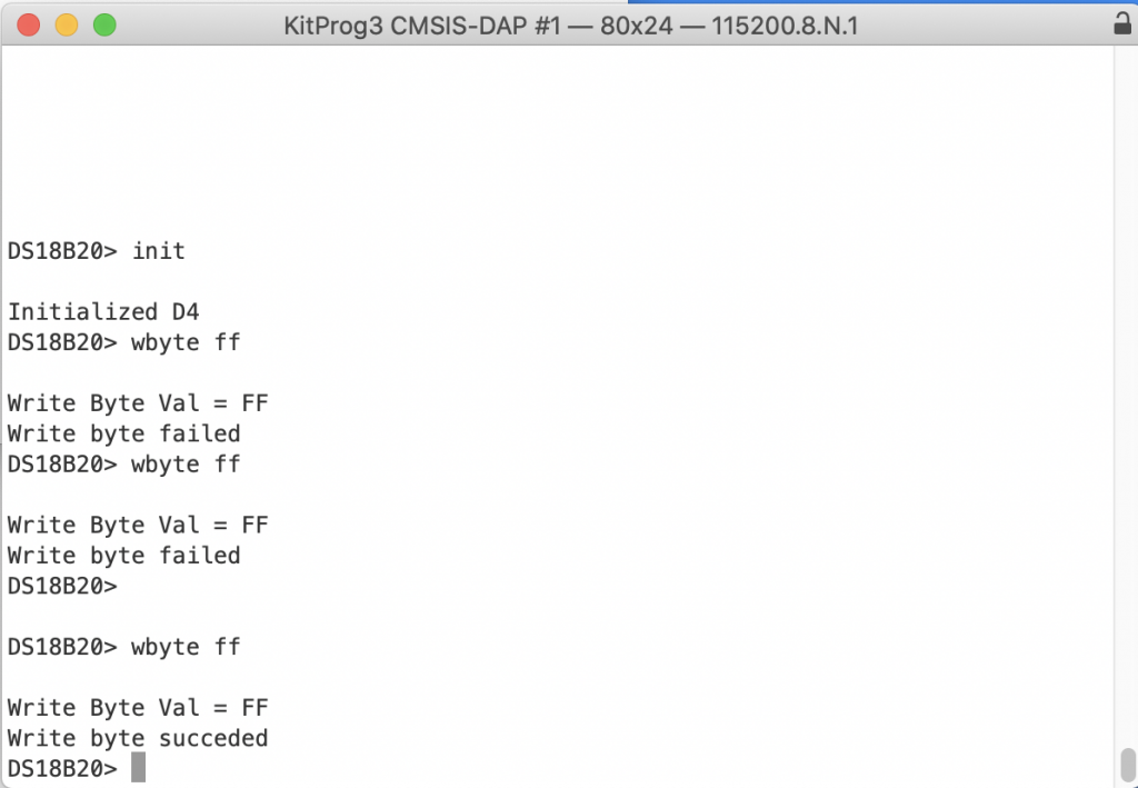
When I programmed this code I got some weird stuff.  Suck.  So to debug it, I put in a command line to let me “wbyte ff” (or whatever byte value).  At the top of usrcmd.c you need to declare the usrcmd_wbyte function and add it to the command table (notice that I chopped out everything around it)

static int usrcmd_wbyte(int argc, char **argv);

static const cmd_table_t cmdlist[] = {

    { "wbyte","write byte", usrcmd_wbyte},

};

Then make a function will will take an argument (the value you want to write).  Notice that the input is a 2 digit hex number.  Yes I known sscanf is dangerous (but in this case I use it only as a debugging tool.)

static int usrcmd_wbyte(int argc, char **argv)
{
    if(argc != 2)
    {
        printf("Invalid argument write  %d\n",argc);
        return 0;
    }

    owb_ret_t ret=OWB_STATUS_OK;

    int val;
    sscanf(argv[1],"%02x",&val);

    printf("Write Byte Val = %02X\n",val);

    ret = owb_write_byte(&bus,(uint8_t)val);

    if(ret == OWB_STATUS_OK)
        printf("Write byte succeeded\n");
    else
        printf("Write byte failed\n");


    return 0;
}

When I run the code I seem to get the write byte function working sometimes and failing sometimes.  What the hell?

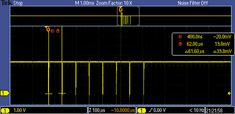
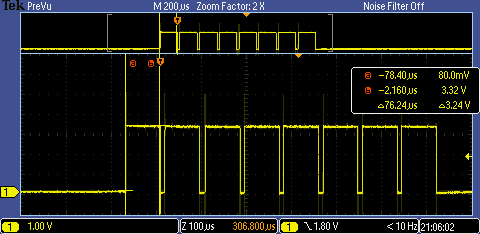
Now, the pain starts.  To debug, I get out the oscilloscope and have a look.  Here is a write of 0xFF which should be 8 short 0 pulses.  But notice that only three get written.  OK, that must mean that the semaphore is timing out. How can that be?

To try to debug that I update a pin to toggle with the semaphore (and git rid of the exit case).

    cyhal_gpio_write(CYBSP_D5,1);
    BaseType_t rsem = xSemaphoreTake(bus->signalSemaphore,1); 
    cyhal_gpio_write(CYBSP_D5,0);

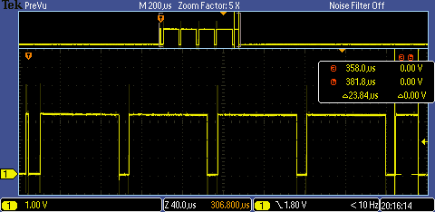
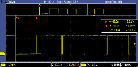
Now I get this (on the debug pin)… notice a very short timeout… then longer ones followed by another partially shorter timeout.

The problem is the semaphore timeout is set to 1.  Should be at least 1 ms right?  Why is that a problem as 1ms is way more than the 60-ish uS you need to wait?

BaseType_t rsem = xSemaphoreTake(bus->signalSemaphore,1);

Classic off by 1 error.  The 1 means expire at the NEXT SysTick, which will happen NO MORE than 1ms from now. Change it to 2.

    BaseType_t rsem = xSemaphoreTake(bus->signalSemaphore,2); 

Now, all the bits come out at a steady rate.

And it works… sometimes…

Deep Sleep

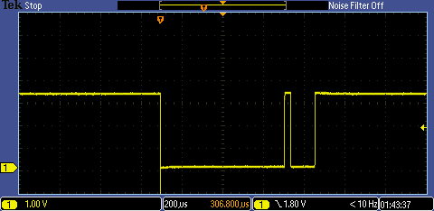
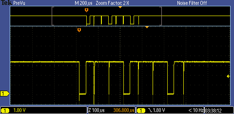
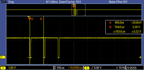
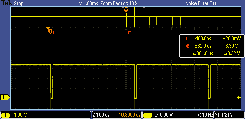
Other times I end up with this picture.  Notice that the space between the start of one bit and the start of the next bit (from a-b on the scope) is 361.6 uS (don’t forget the 0.6 uS).

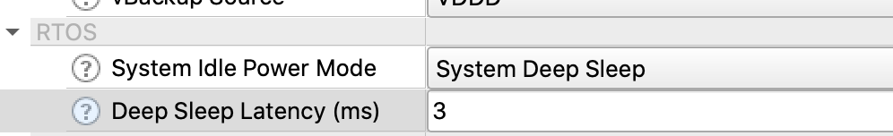
Why are the interrupts getting delayed?  The answer is the chip is in deep sleep (or going to deep sleep) when the interrupt from the timer happens.  And when the deep sleep is happening, it takes a bit of time to go to deep sleep, then to wake up.  To fix this go into the system configurator and change the Deep Sleep Latency.

Change the timeout to 3

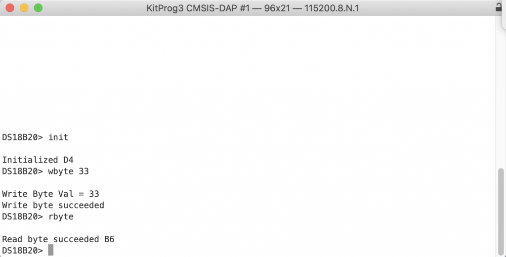
Now it works.. here is a write of 0xFE

Implement the Read Bit

Now that the write bit is working, move the read bit function to the same scheme.  Notice that I use the compare to trigger the read of the pin.  In the read code I probably should have done a critical section from the start of the 0 to the start of the timer so that an interrupt doesn’t occur before the timer gets started.

void read_bit_event_callback(void *callback_arg, cyhal_timer_event_t event)
{
    OneWireBus *bus = (OneWireBus *)callback_arg;

    if(event & CYHAL_TIMER_IRQ_CAPTURE_COMPARE)
    {
        bus->scratchBitValue = cyhal_gpio_read(bus->pin);
    }
    if(event & CYHAL_TIMER_IRQ_TERMINAL_COUNT)
    {
        BaseType_t xHigherPriorityTaskWoken;
        xHigherPriorityTaskWoken = pdFALSE;
        xSemaphoreGiveFromISR(bus->signalSemaphore,&xHigherPriorityTaskWoken);
        portYIELD_FROM_ISR( xHigherPriorityTaskWoken );
    }

}


owb_ret_t owb_read_bit( OneWireBus *bus, uint8_t *bit)
{
    owb_ret_t rval;

    cyhal_timer_cfg_t cfgBit = {
        .is_continuous = false,
        .direction = CYHAL_TIMER_DIR_UP,
        .is_compare = true,
        .compare_value = 10,
        .period = 61,
        .value = 0
    };

    cyhal_timer_configure(&bus->bitTimer,&cfgBit);

    cyhal_timer_register_callback(&bus->bitTimer,read_bit_event_callback,bus);
    cyhal_timer_enable_event(&bus->bitTimer,CYHAL_TIMER_IRQ_TERMINAL_COUNT|CYHAL_TIMER_IRQ_CAPTURE_COMPARE,5,true);

    // Pull a 0
    cyhal_gpio_write(bus->pin,0);
    CyDelayUs(1);
    cyhal_gpio_write(bus->pin,1);

    cyhal_timer_reset(&bus->bitTimer);
    cyhal_timer_start(&bus->bitTimer);

    BaseType_t rsem = xSemaphoreTake(bus->signalSemaphore,2); // Then entire write cycle is 61uS so 2ms would be a major failure
    *bit = bus->scratchBitValue;

    if(rsem == pdTRUE)
        rval = OWB_STATUS_OK;
    else
        rval = OWB_STATUS_ERROR;

    return rval;
}

In fact as I look at this code, I decide that I had better to fix the critical section.  Here is the updated read code.

    void taskENTER_CRITICAL();

    cyhal_gpio_write(bus->pin,0);     // Pull a 0
    CyDelayUs(1);
    cyhal_gpio_write(bus->pin,1);

    cyhal_timer_start(&bus->bitTimer);
    void taskEXIT_CRITICAL( );

And the updated write code

    taskENTER_CRITICAL();
    cyhal_gpio_write(bus->pin,0);

    cyhal_timer_start(&bus->bitTimer);
    taskEXIT_CRITICAL();

In the next article I’ll show you code to actually read the temperature.


PSoC 6 SDK OneWire Bus (Part 2) : Implement Read & Write

Summary

In this article I will explain how to implement (badly) the one wire bus read & write functions using the PSoC 6 SDK.  This is one of many articles that are part of a series discussing the implementation:

Story

In the previous article, I built a test framework inside of a PSoC 6 FreeRTOS project.  This includes a command line shell which will enable me to execute functions based on typed commands.  This means I can use the CLI shell to debug my interface.  To get going testing, I bought a DS18B20 temperature sensor from Mouser.

Then wired it like this:

Here is a picture of the test jig.  It looks like I used 4200 ohms instead of 4400 ohms, oh well it seems to work.

Init

Init seems like a good place to start.  To have a one wire bus you need to have a GPIO to read/drive.  So, that will be the only argument to the initialization function.  In the implementation I will use a common semaphore to handle blocking functions (line 13).  On lines 15-17 I initialize a timer to handle the requirements of reset, read and writes (more on this later).  At the end on line 20 I initialize the GPIO.

#include "owb.h"
#include <stdint.h>
#include "cyhal.h"
#include "cybsp.h"
#include "task.h"
#include <stdbool.h>
#include <stdio.h>

owb_ret_t owb_init(OneWireBus *bus)
{
    cy_rslt_t rslt;

    bus->signalSemaphore = xSemaphoreCreateBinary();

    rslt = cyhal_timer_init(&bus->bitTimer,NC,0);
    CY_ASSERT(rslt == CY_RSLT_SUCCESS);
    rslt = cyhal_timer_set_frequency(&bus->bitTimer,1000000);
    
    CY_ASSERT(rslt == CY_RSLT_SUCCESS);
    rslt = cyhal_gpio_init(bus->pin,CYHAL_GPIO_DIR_BIDIRECTIONAL,CYHAL_GPIO_DRIVE_OPENDRAINDRIVESLOW,true);
    CY_ASSERT(rslt == CY_RSLT_SUCCESS);
    return OWB_STATUS_OK;    
}

In the usrcmd.c I need to add includes for the new stuff.

#include "cybsp.h"
#include "owb.h"

The next step is to add the “init” command to usrcmd.c  This is accomplished by adding a function header for usrcmd_init and adding it to the table of legal commands.

static int usrcmd_init(int argc, char **argv);

typedef struct {
    char *cmd;
    char *desc;
    USRCMDFUNC func;
} cmd_table_t;

static const cmd_table_t cmdlist[] = {
    { "help", "This is a description text string for help command.", usrcmd_help },
    { "info", "This is a description text string for info command.", usrcmd_info },
    { "clear", "Clear the screen", usrcmd_clear },
    { "printargs","print the list of arguments", usrcmd_printargs},
    { "init","Initialize the 1-wire bus", usrcmd_init},

};

Then you need to add the usrcmd_init function to call the owb init.

static OneWireBus bus;
static int usrcmd_init(int argc, char **argv)
{
    bus.pin = CYBSP_D4;
    owb_init(&bus);
    printf("Initialized D4\n");

    return 0;
}

Now test it.  All good.

Reset

In order to reset the bus you follow this process

  1. Pull down the bus for trstl=480uS
  2. Let the bus go back to 1 (remember that it is restive pull-up)
  3. Wait another trsth=480uS
  4. If there is a slave device on the bus it will pull down the bus at some point to indicate a “presence detect”

From the data sheet you can see that the low& high times = 480uS.  At some point during the high period the slave will pull the bus down for 15->60uS

In order to implement the reset I will modify the owb.c file.  To meet the timing requirements I will use a cyhal_timer.  The cyhal_timer is implemented in the Cypress PDL at a Cy_TCPWM_Timer which is then implemented in the hardware as a timer counter.  In this configuration the timer has:

  • A Counter (an up or down counter)
  • A Compare (a register which can be compared with the counter to trigger events)
  • A Period (a register which is compared to the counter to reset the counter back to 0).   This event is also called the “terminal count”

For this implementation I will setup a timer with

  1. Input clock 1Mz (aka 1uS per count)
  2. An up counter
  3. Starts at 0
  4. Compare value = 480 (means trigger an interrupt at 480uS)
  5. Period = 960 (means trigger an interrupt at 480uS)
  6. One shot (stop counting when you get to period (aka Terminal Count))

The code will

  1. Configure the timer (line 41-52)
  2. Pull a 0 onto the bus (line 54)
  3. Start the timer (line 56)
  4. At the compare value 480uS reset the bus to 1 using the event handler (line 20) and setup the GPIO trigger a fall event interrupt (line 21-22)
  5. At the period release the semaphore (27-30)
  6. After the compare value if the GPIO pulls down, use the GPIO interrupt to record the presence of a device (line 10)
/////////////////////////////////////////////////////////////////////////////////////////////////////////////
// Reset
/////////////////////////////////////////////////////////////////////////////////////////////////////////////
static void reset_gpio_event_callback(void *callback_arg, cyhal_gpio_event_t event)
{
    OneWireBus *bus = (OneWireBus *)callback_arg;

    if(event & CYHAL_GPIO_IRQ_FALL)
    {
        bus->detect = true;
    }
}

static void reset_timer_event_callback(void *callback_arg, cyhal_timer_event_t event)
{
    OneWireBus *bus = (OneWireBus *)callback_arg;

    if(event & CYHAL_TIMER_IRQ_CAPTURE_COMPARE)
    {
        cyhal_gpio_write(bus->pin,1);
        cyhal_gpio_register_callback(bus->pin, reset_gpio_event_callback,(void *)bus);
        cyhal_gpio_enable_event(bus->pin,CYHAL_GPIO_IRQ_FALL,5,true);
    }
    if(event & CYHAL_TIMER_IRQ_TERMINAL_COUNT)
    {

        BaseType_t xHigherPriorityTaskWoken;
        xHigherPriorityTaskWoken = pdFALSE;
        xSemaphoreGiveFromISR(bus->signalSemaphore,&xHigherPriorityTaskWoken);
        portYIELD_FROM_ISR( xHigherPriorityTaskWoken );
    }
 
}

owb_ret_t owb_reset(OneWireBus *bus, bool *result)
{
    owb_ret_t rval = OWB_STATUS_OK;

    bus->detect = false;

    cyhal_timer_cfg_t cfgBit = {
        .is_continuous = false,
        .direction = CYHAL_TIMER_DIR_UP,
        .is_compare = true,
        .compare_value = 480,
        .period = 960,
        .value = 0
    };
    cyhal_timer_configure(&bus->bitTimer,&cfgBit);
    cyhal_timer_reset(&bus->bitTimer);
    cyhal_timer_register_callback(&bus->bitTimer,reset_timer_event_callback,bus); 
    cyhal_timer_enable_event(&bus->bitTimer,CYHAL_TIMER_IRQ_ALL,5,true);

    cyhal_gpio_write(bus->pin,0);

    cyhal_timer_start(&bus->bitTimer);

    xSemaphoreTake(bus->signalSemaphore,2); // worst case is really 960uS
    cyhal_gpio_enable_event(bus->pin,CYHAL_GPIO_IRQ_FALL,5,true);
    return rval;
}

Once I have the owb_init code I add the init command to usrcmd.c.

static int usrcmd_reset(int argc, char **argv)
{
    bool result;
    owb_reset(&bus,&result);
    if(bus.detect)
    {
        printf("Reset Succeeded\n");

    }
    else

        printf("Reset Failed\n");

    return 0;
}

When I run it, I get this nice picture from the oscilliscope.

Write

In the ds18b20.c file I see that the author has three functions of interest.  In the implementation owb_write_bytes will call owb_write byte and owb_write_byte will call owb_write bit.

owb_ret_t owb_write_bit( OneWireBus *bus, uint8_t val);
owb_ret_t owb_write_byte( OneWireBus *bus, uint8_t val);
owb_ret_t owb_write_bytes( OneWireBus *bus, uint8_t *buffer, uint32_t length);

The one wire protocol has the following steps.

In order to write a “0” you need to

  1. Pull down the bus (write a 0)
  2. Wait 60uS
  3. Write a 1
  4. Wait 1uS (to allow the next “slot” to start

In order to write a “1” you need to

  1. Pull down the bus (write a 0)
  2. Wait 1 uS
  3. Write a 1
  4. Wait 60uS (to allow the next “slot” to start)

Notice that the minimum write slot is 60uS and the maximum is 120uS.  Here is a picture from the data sheet.

For the first implementation of owb_write_bit I will use a simple “CyDelayUs”  to implement the delays (this is a bad idea, but is a ‘cheap’ way to get going).

owb_ret_t owb_write_bit(OneWireBus *bus,uint8_t val)
{
    owb_ret_t rval = OWB_STATUS_OK;
    cyhal_gpio_write(bus->pin,0);
    if(val == 0)
    {
        CyDelayUs(60);
        cyhal_gpio_write(bus->pin,1);
        CyDelayUs(2);

    }
    else
    {
        CyDelayUs(1);
        cyhal_gpio_write(bus->pin,1);
        CyDelayUs(60);
    }
    return rval;
}

The write byte function just loops through the 8-bit and uses the owb_write_bit function.  Notice that it is least significant bit first.

owb_ret_t owb_write_byte( OneWireBus *bus, uint8_t val)
{
    owb_ret_t ret = OWB_STATUS_OK;
    for(int i=0;i<8;i++)
    {
        ret = owb_write_bit(bus,(val>>i) & 0x01);
        if(ret != OWB_STATUS_OK)
            return ret;        
    }
    return OWB_STATUS_OK;
}

And write_bytes (multiple) just loops through the buffer calling the write_byte function.

owb_ret_t owb_write_bytes( OneWireBus *bus, uint8_t *buffer, uint32_t length)
{
    owb_ret_t ret = OWB_STATUS_OK;
    for(int i=0;i<length;i++)
    {
        ret = owb_write_byte(bus,buffer[i]);
        if(ret != OWB_STATUS_OK)
            return ret;
    }
    return OWB_STATUS_OK;
}

Now that I have the three write functions I will add a new command to usrcmd.c  This function lets the user type a command like “wbyte a1” where he/she can input a 2-character hex command.  Yes, I use the sscanf function which is unsafe… but cheap for a test rig.

static int usrcmd_wbyte(int argc, char **argv)
{
    if(argc != 2)
    {
        printf("Invalid argument write  %d\n",argc);
        return 0;
    }

    owb_ret_t ret=OWB_STATUS_OK;

    int val;
    sscanf(argv[1],"%02x",&val);

    printf("Write Byte Val = %02X\n",val);

    ret = owb_write_byte(&bus,(uint8_t)val);

    if(ret == OWB_STATUS_OK)
        printf("Write byte succeeded\n");
    else
        printf("Write byte failed\n");


    return 0;
}

When I program and launch the project I end up here.

OK that is easy enough to fix, I just ran out of stack in the ntshell thread.

    xTaskCreate(ntShellTask, "nt shell task", configMINIMAL_STACK_SIZE*3,0 /* args */ ,0 /* priority */, 0);

Now when I run it I am off to the races.

Here is an example of “wbyte ff”

What about “owb_write_rom_code”?  I don’t know what it does, but Ill figure it out as I integrate the rest of the library.

Read

When I examine the ds18b20.c file I find these three read functions, which mirror the write functions.

owb_ret_t owb_read_bit( OneWireBus *bus, uint8_t *bit);
owb_ret_t owb_read_byte( OneWireBus *bus, uint8_t *byte);
owb_ret_t owb_read_bytes( OneWireBus *bus, uint8_t *buffer, uint32_t length);

To read a bit you follow a a very similar process to the write.

  1. Write a 0 on the bus
  2. Wait 1uS
  3. Write a 1 on the bus (release the bus)
  4. Wait 5uS
  5. Read (the slave will pull a 0 or a 1 onto the bus)
  6. Wait 55uS to the end of the slot

Here is a picture

The code uses a really bad busy-wait delay (but it is a good starting place to figure out what is happening)

owb_ret_t owb_read_bit( OneWireBus *bus, uint8_t *bit)
{
    owb_ret_t rval = OWB_STATUS_OK;

    cyhal_gpio_write(bus->pin,0);
    CyDelayUs(1);
    cyhal_gpio_write(bus->pin,1);
    CyDelayUs(5);

    *bit = cyhal_gpio_read(bus->pin);
    CyDelayUs(55);
    return rval;
}

To read a byte, just read 8 bits using the owb_read_bit function

owb_ret_t owb_read_byte( OneWireBus *bus, uint8_t *byte)
{
    uint8_t bit;
    owb_ret_t ret = OWB_STATUS_OK;

    *byte = 0;
    for(int i=0;i<8;i++)
    {
        ret = owb_read_bit(bus,&bit);
        if(ret != OWB_STATUS_OK)
            return ret;
        *byte = *byte | (bit<<i);
    }
    return OWB_STATUS_OK;
}

To read an array of bytes, use a loop of read_byte

owb_ret_t owb_read_bytes( OneWireBus *bus, uint8_t *buffer, uint32_t count)
{
    owb_ret_t ret = OWB_STATUS_OK;
    for(int i=0;i<count;i++)
    {
        ret = owb_read_byte(bus,&buffer[i]);
        if(ret != OWB_STATUS_OK)
            return ret;       
    }
    return ret;
}

Now that you have a read and a write, update the usrcmd.c to add a “rbyte” command to the CLI

static int usrcmd_rbyte(int argc, char **argv)
{

    owb_ret_t ret=OWB_STATUS_OK;

    uint8_t val;
 
    ret = owb_read_byte(&bus,&val);

    if(ret == OWB_STATUS_OK)
        printf("Read byte succeeded %02x\n",val);
    else
        printf("Read byte failed\n");


    return 0;
}

When I program the kit I can send a 0x33 (which will make the sensor respond more on this later), then read the first byte of the ROM

When you look at the scope picture (from right to left) you can see 10110110 which sure enough is B6.  The thin gaps are 1’s and the wide gaps are 0’s

In the next article Ill deal with the stupid CyDelay’s

PSoC 6 SDK OneWire Bus (Part 1) : Build Basic Project

Summary

This is the first article in a series about my journey implementing PSoC 6 SDK libraries for the Maxxim One Wire Bus and the DS18B20 temperature sensor.

As you can see there will be many parts to this story:

Story

I recently got a twitter message from a gentleman named “Neeraj Dhekale”.  He asked about a library for a one wire sensor for PSoC, actually to be specific he asked about a component for a PSoC 4.

Then I asked him what sensor and responded that he wanted to use the Maxxim DS18B20 temperature sensor.

This sensor is a one wire temperature sensor, here is a bit of snapshot from the data sheet.

After reading the data sheet I decided that I really didn’t want to implement a complete library for this sensor.  So, I started looking around for a driver library.  After googling around a little bit I found a library on GitHub (https://github.com/DavidAntliff/esp32-ds18b20) which looked promising, even though it is ESP32 specific.

But, after looking at this GitHub library a bit, I decide to start from there.

Before I get started two comments.

  1. He asked for PSoC 4 … but I am going to do PSoC 6 (because I can use Modus Toolbox).  There is no reason why this wouldn’t work on PSoC 4 – but it would take a bit of work
  2. I can’t think of a good reason to use 1-wire, it sure seems like I2C would be simpler

Build a Base Project

I start this whole effort by creating a new project for the CY8CKIT-062S2-43012 (because that happens to be the kit on my desk at the moment)

I will use the IoT Expert FreeRTOS Template project

For debugging this whole thing I will use a command line shell.  To get this into the project I add the ntshell library. Run “make modlibs” to start the library manager.

In the library manager pick the “ntshell” library

To develop this project I want to use Visual Studio code.  So, I run “make vscode” (to create the configuration files) and start vscode by running “code .”

When VSCODE starts up it looks like this:

In order to use the ntshell library you need to shuffle the files around a little bit.  Move the ntshell.h/.c into the main project by doing a drag/drop in the explorer window.

It will ask you really want to move the files

Once it is done, the ntshell functions which you need to customize will be part of the project.

To use the ntshell, you need to add the task to main.c

#include "cy_pdl.h"
#include "cyhal.h"
#include "cybsp.h"
#include "cy_retarget_io.h"
#include <stdio.h>
#include "FreeRTOS.h"
#include "task.h"

#include "ntshell.h"
#include "ntlibc.h"
#include "psoc6_ntshell_port.h"

// Global variable with a handle to the shell
ntshell_t ntshell;

void ntShellTask()
{

  printf("Started ntshell\n");
  setvbuf(stdin, NULL, _IONBF, 0);
  ntshell_init(
	       &ntshell,
	       ntshell_read,
	       ntshell_write,
	       ntshell_callback,
	       (void *)&ntshell);
  ntshell_set_prompt(&ntshell, "DS18B20> ");
  vtsend_erase_display(&ntshell.vtsend);
  ntshell_execute(&ntshell);
}

And start the task

    xTaskCreate(ntShellTask, "nt shell task", configMINIMAL_STACK_SIZE*2,0 /* args */ ,0 /* priority */, 0);

Build and compile

And you should have a working project.

Run “make program” to get the board going

arh (master *) OWB_DS18B20 $ make program
Tools Directory: /Applications/ModusToolbox/tools_2.1
Prebuild operations complete
Commencing build operations...
Tools Directory: /Applications/ModusToolbox/tools_2.1
Initializing build: mtb-example-psoc6-empty-app Debug CY8CKIT-062S2-43012 GCC_ARM
Auto-discovery in progress...
-> Found 202 .c file(s)
-> Found 50 .S file(s)
-> Found 27 .s file(s)
-> Found 0 .cpp file(s)
-> Found 0 .o file(s)
-> Found 4 .a file(s)
-> Found 450 .h file(s)
-> Found 0 .hpp file(s)
-> Found 0 resource file(s)
Applying filters...
Auto-discovery complete
Constructing build rules...
Build rules construction complete
==============================================================================
= Building application =
==============================================================================
Building 181 file(s)
==============================================================================
= Build complete =
==============================================================================
Calculating memory consumption: CY8C624ABZI-D44 GCC_ARM -Og
---------------------------------------------------- 
| Section Name         |  Address      |  Size       | 
---------------------------------------------------- 
| .cy_m0p_image        |  0x10000000   |  5972       | 
| .text                |  0x10002000   |  49532      | 
| .ARM.exidx           |  0x1000e17c   |  8          | 
| .copy.table          |  0x1000e184   |  24         | 
| .zero.table          |  0x1000e19c   |  8          | 
| .data                |  0x080022e0   |  1688       | 
| .cy_sharedmem        |  0x08002978   |  8          | 
| .noinit              |  0x08002980   |  148        | 
| .bss                 |  0x08002a14   |  985176     | 
| .heap                |  0x080f3270   |  46480      | 
---------------------------------------------------- 
Total Internal Flash (Available)          2097152    
Total Internal Flash (Utilized)           59468      
Total Internal SRAM (Available)           1046528    
Total Internal SRAM (Utilized)            1033500    
Programming target device... 
Open On-Chip Debugger 0.10.0+dev-3.0.0.665 (2020-03-20-17:12)
Licensed under GNU GPL v2
For bug reports, read
http://openocd.org/doc/doxygen/bugs.html
Info : auto-selecting first available session transport "swd". To override use 'transport select <transport>'.
adapter speed: 2000 kHz
** Auto-acquire enabled, use "set ENABLE_ACQUIRE 0" to disable
cortex_m reset_config sysresetreq
Info : Using CMSIS loader 'CY8C6xxA_SMIF' for bank 'psoc6_smif0_cm0' (footprint 6485 bytes)
Warn : SFlash programming allowed for regions: USER, TOC, KEY
Info : CMSIS-DAP: SWD  Supported
Info : CMSIS-DAP: FW Version = 2.0.0
Info : CMSIS-DAP: Interface Initialised (SWD)
Info : SWCLK/TCK = 1 SWDIO/TMS = 1 TDI = 0 TDO = 0 nTRST = 0 nRESET = 1
Info : CMSIS-DAP: Interface ready
Info : KitProg3: FW version: 1.11.159
Info : KitProg3: Pipelined transfers disabled, please update the firmware
Warn : *******************************************************************************************
Warn : * KitProg firmware is out of date, please update to the latest version using fw-loader at *
Warn : * ModusToolbox/tools/fw-loader                                                            *
Warn : *******************************************************************************************
Info : VTarget = 3.263 V
Info : kitprog3: acquiring PSoC device...
Info : clock speed 2000 kHz
Info : SWD DPIDR 0x6ba02477
Info : psoc6.cpu.cm0: hardware has 4 breakpoints, 2 watchpoints
Info : psoc6.cpu.cm0: external reset detected
***************************************
** Silicon: 0xE402, Family: 0x102, Rev.: 0x11 (A0)
** Detected Device: CY8C624ABZI-S2D44A0
** Detected Main Flash size, kb: 2048
** Flash Boot version: 3.1.0.45
** Chip Protection: NORMAL
***************************************
Info : psoc6.cpu.cm4: hardware has 6 breakpoints, 4 watchpoints
Info : psoc6.cpu.cm4: external reset detected
Info : Listening on port 3333 for gdb connections
Info : Listening on port 3334 for gdb connections
Info : kitprog3: acquiring PSoC device...
target halted due to debug-request, current mode: Thread 
xPSR: 0x41000000 pc: 0x00000190 msp: 0x080ff800
** Device acquired successfully
** psoc6.cpu.cm4: Ran after reset and before halt...
target halted due to debug-request, current mode: Thread 
xPSR: 0x01000000 pc: 0x0000012a msp: 0x080ff800
** Programming Started **
auto erase enabled
Info : Flash write discontinued at 0x10001754, next section at 0x10002000
Info : Padding image section 0 at 0x10001754 with 172 bytes (bank write end alignment)
[100%] [################################] [ Erasing     ]
[100%] [################################] [ Programming ]
Info : Padding image section 1 at 0x1000e844 with 444 bytes (bank write end alignment)
[100%] [################################] [ Erasing     ]
[100%] [################################] [ Programming ]
wrote 57856 bytes from file /Users/arh/proj/xxx/OWB_DS18B20/build/CY8CKIT-062S2-43012/Debug/mtb-example-psoc6-empty-app.hex in 2.294771s (24.621 KiB/s)
** Programming Finished **
** Verify Started **
verified 57240 bytes in 0.155447s (359.598 KiB/s)
** Verified OK **
** Resetting Target **
shutdown command invoked
arh (master *) OWB_DS18B20 $

And you should have a working project (with a blinking led and a command line)

Add the DS18B20 Library

Now that I have a working project the next step is to clone the DS18B20 library into my project.  This is done using

  • git clone https://github.com/DavidAntliff/esp32-ds18b20

The next step is to establish how bad things are with the new library.  So run the compiler.

When I look at the ds18b20.c file I can see that there are some obvious problems

#include "freertos/FreeRTOS.h"
#include "freertos/task.h"
#include "driver/gpio.h"
#include "esp_system.h"
#include "esp_log.h"
#include "ds18b20.h"
#include "owb.h"

Fix those:

#include "FreeRTOS.h"
#include "task.h"
//#include "driver/gpio.h"
//#include "esp_system.h"
//#include "esp_log.h"
#include "ds18b20.h"
//#include "owb.h"

Run the compiler again.  Now I am missing owb.h which is the public header file for the one wire bus.

In file included from esp32-ds18b20/ds18b20.c:47:0:
./esp32-ds18b20/include/ds18b20.h:37:10: fatal error: owb.h: No such file or directory
#include "owb.h"

I now make a directory to hold the new owb files called “p6sdk-onewire”.  Then I add a file “owb.h” (as a blank file)

When I run the compiler again, there are now two classes or error … owb and esp32 logging function. Here is an example of the ESP_ problems.

esp32-ds18b20/ds18b20.c:249:17: warning: implicit declaration of function 'ESP_LOG_BUFFER_HEX_LEVEL' [-Wimplicit-function-declaration]
ESP_LOG_BUFFER_HEX_LEVEL(TAG, scratchpad, count, ESP_LOG_DEBUG);
^~~~~~~~~~~~~~~~~~~~~~~~
esp32-ds18b20/ds18b20.c:249:66: error: 'ESP_LOG_DEBUG' undeclared (first use in this function)
ESP_LOG_BUFFER_HEX_LEVEL(TAG, scratchpad, count, ESP_LOG_DEBUG);

And here is an example of the owb problems.

esp32-ds18b20/ds18b20.c: In function 'ds18b20_wait_for_conversion':
esp32-ds18b20/ds18b20.c:504:30: error: request for member 'use_parasitic_power' in something not a structure or union
if (ds18b20_info->bus->use_parasitic_power)
^~
esp32-ds18b20/ds18b20.c: At top level:
esp32-ds18b20/ds18b20.c:568:54: error: unknown type name 'OneWireBus'
DS18B20_ERROR ds18b20_check_for_parasite_power(const OneWireBus * bus, bool * present)
^~~~~~~~~~
esp32-ds18b20/ds18b20.c: In function 'ds18b20_check_for_parasite_power':
esp32-ds18b20/ds18b20.c:577:44: error: 'OWB_ROM_SKIP' undeclared (first use in this function); did you mean 'CY_ROM_SIZE'?
if ((err = owb_write_byte(bus, OWB_ROM_SKIP)) == DS18B20_OK)
^~~~~~~~~~~~
CY_ROM_SIZE
make[1]: *** [/Users/arh/proj/xxx/OWB_DS18B20/build/CY8CKIT-062S2-4301

To make this thing go, I edit ds18b20.c file and add logging templates (just stub functions that don’t do anything)

void ESP_LOGD(const char * code, char *val,...)
{
}
void ESP_LOGE(const char * code, ...)
{
}
void ESP_LOGW(const char *code,...)
{
}
#define ESP_LOG_DEBUG 0
void ESP_LOG_BUFFER_HEX_LEVEL(const char *code,...)
{
}
uint64_t esp_timer_get_time()
{
return 0;
}

Create owb.h

If I was smart, I would have started with David Antliff “owb” library.  But I don’t.  What I do is search through “ds18b20.c” and find every function call to owb_ and then copy those function calls into owb.h (my new file).  Then I fix the function calls to have correct prototypes based on what I see in the ds18b20 library.  Here is what my owb.h file looks like after that process.

#ifndef OWB_H
#define OWB_H
#ifdef __cplusplus
extern "C" {
#endif
#define OWB_ROM_MATCH 0
#define OWB_ROM_SKIP 0
#include <stdint.h>
#include "cyhal.h"
#include "FreeRTOS.h"
#include "semphr.h"
typedef struct  
{
cyhal_gpio_t  pin;
bool use_parasitic_power;
SemaphoreHandle_t signalSemaphore;
cyhal_timer_t bitTimer;
bool detect;
SemaphoreHandle_t owb_num_active;
} OneWireBus;        
typedef struct {
uint8_t romAddr[8];
} OneWireBus_ROMCode;
typedef enum {
OWB_STATUS_OK,
OWB_STATUS_ERROR,
} owb_ret_t ;
owb_ret_t owb_init(OneWireBus *bus);
owb_ret_t owb_reset(OneWireBus *bus, bool *result);
owb_ret_t owb_write_bit( OneWireBus *bus, uint8_t val);
owb_ret_t owb_write_byte( OneWireBus *bus, uint8_t val);
owb_ret_t owb_write_bytes( OneWireBus *bus, uint8_t *buffer, uint32_t length);
owb_ret_t owb_write_rom_code(OneWireBus *bus, OneWireBus_ROMCode romcode);
owb_ret_t owb_read_bit( OneWireBus *bus, uint8_t *bit);
owb_ret_t owb_read_byte( OneWireBus *bus, uint8_t *byte);
owb_ret_t owb_read_bytes( OneWireBus *bus, uint8_t *buffer, uint32_t length);
owb_ret_t owb_crc8_bytes(uint32_t val, uint8_t *buffer, uint32_t length);
void   owb_set_strong_pullup( OneWireBus *bus, bool val);
#endif
#ifdef __cplusplus
}
#endif

When I run the compiler again things look way better (just some complaining about const datatypes) and a complaint about the include path.  The include path thing is visual studio code not knowing that I added a new directory called p6sdk-onewire.

To fix the include path I run “make vscode” which tells VSCODE about the new directory.

That is a good place to split this article.  In the next article I will add functions to read and write the bus.

Keithley DAQ6510 & 7700

Summary

This article walks you through the first use of a Keithley 7700 20-channel multiplexer module attached to a Keithley DAQ6510.

Keithley describes the module in the data sheet as “The 7700 plug-in module offers 20 channels of 2-pole or 10 channels of 4-pole multiplexer switching that can be configured as two independent banks of multiplexers. There are two additional protected channels for current measurements. Automatic CJC
is provided so that no other accessories are required to make thermocouple temperature measurements. In addition, the 7700 contains latching electromechanical relays that enable signal bandwidths of up to 50 MHz. The 7700 is ideal for RTD, thermistor, and thermocouple temperature applications.”  And they give a nice picture:

And a “schematic”:

The Story

When I bought my original DAQ6510 from Mouser, they did not have a 7700 multiplexer module in stock.  So, I decided to buy one on eBay, which I was really hoping would work.  The module was salvaged out of some installation somewhere in California by a company called “Silicon Salvage”  I was a little bit worried about it because the multiplexor uses actual mechanical relays which wear out in somewhere between 100K and 100M switches.  That seemed like a lot, but who knows.

Assemble

When the unit arrived it seemed OK.  So I put my lab assistant to assembling and testing it.  To test it I bought a bunch of really inexpensive alligator to banana plug wires from China.

Then Nicholas clipped off the alligator ends and tinned the wires.  How about that classic soldering vice?  That was bought at an antique sale in Georgetown Kentucky a few years ago and works great for this kind of thing.  It is also heavy enough to kill Zombies with.

Then he installed the jumper wires onto the board.

Try it out

When everything was button up it was time to test.  Start with turning on the meter and pressing the rear button.

Then press “Build Scan”

Press the “Plus” symbol (to create a new list of channel and settings) to scan

Select some channels and press OK.  It turned out that we tested 3-wires at a time because I used a 3-channel power to supply to setup the voltages to test.

Then pick out DC Voltage

Press the Start Button to launch the meter to scan through the channels and save the values.

And the screen will look like this.

If you press the view scan status you will end on a screen like this.  Notice that you can only see channel 120.  To fix this press the “120”

Then select the other two channels

And you will now see all of the voltages

Here is a picture of the whole thing

Channel Grid App

The DAQ also have a function to display a grid of the channel values.  To get there Press the Apps button

Press “Channel Grid” then Run

It will then ask you to start the Scan

And when it is done you will have the voltages.

It would be really nice if this App had button to re-scan.  Or potentially a way to run the scans in a loop.  I am pretty sure that they give you a way to create Apps to run on this meter… so I suppose I’ll need to fix their App.

Reading Table

You can also view the scan data in a table.  To do this, press “Menu”

Press the “Reading Table”

Which will take you to see a table of the previous scan values.

Step Scan

You can also manually scan the channels by running a “Step Scan”.  Press the “Step Scan” button.

Which will read and display the first channel.

Then you can repeatedly click to work your way through all of the channels.

Stupid Python Tricks: VSCODE c_cpp_properties.json for Linux Kernel Development

Summary

This article shows you how to create a Python program that creates a Visual Studio Code c_cpp_properties.json which will enable intellisense when editing Linux Kernel Modules for Device Drivers.

Story

I am working my way through understanding, or at least trying to understand, Linux Kernel Modules – specifically Linux Device Drivers.  I have been following through the book Linux Device Drivers Development by John Madieu

There are a bunch of example codes in the book which you can “git”

$ git remote -v
origin  https://github.com/PacktPublishing/Linux-Device-Drivers-Development (fetch)
origin  https://github.com/PacktPublishing/Linux-Device-Drivers-Development (push)
$

When I started looking at the Chapter02 example I first opened it up in Visual Studio Code.  Where I was immediately given a warning about Visual Studio Code not knowing where to find <linux/init.h>

And, when you try to click on the “KERN_INFO” symboled you get this nice message.

In order to fix this you need to setup the “c_cpp_propertiese.json” to tell Visual Studio Code how to make intellisense work correctly. But, what is c_cpp_properties.json?

C_CPP_PROPERTIES.JSON

On the Visual Studio Code website they give you a nice description of the schema.  Here is a screenshot from their website.

The “stuff” that seems to matter from this list is the “includePath” which tells intellisense the #includes and #defines.  OK.  How do I figure out where to find all of the files and paths for that?

make –dry-run

When you look at the Makefile it doesn’t appear to help very much.  I don’t know about you guys, but I actually dislike “Make” way more than I dislike Python :-).  What the hell is this Makefile telling you to do?

On line 3 the Makefile creates a variable called “KERNELDIR” and sets the value to the result of the shell command “uname -r” plus “/lib/modules” at the first and “/build” at the end.  If I run the command “uname -r” on my system I get “4.15.0-99-generic”

Then on line 9 it calls make with a “-C” option

obj-m := helloworld-params.o helloworld.o
KERNELDIR ?= /lib/modules/$(shell uname -r)/build
all default: modules
install: modules_install
modules modules_install help clean:
$(MAKE) -C $(KERNELDIR) M=$(shell pwd) $@

Which tells Make to “change directory”

$ make --help
Usage: make [options] [target] ...
Options:
-b, -m                      Ignored for compatibility.
-B, --always-make           Unconditionally make all targets.
-C DIRECTORY, --directory=DIRECTORY
Change to DIRECTORY before doing anything

OK when I look in that directory I see a bunch of stuff.  Most importantly a Makefile.

$ cd /lib/modules/4.15.0-99-generic/build
$ ls
arch   crypto         firmware  init    Kconfig  Makefile        net      security  ubuntu
block  Documentation  fs        ipc     kernel   mm              samples  sound     usr
certs  drivers        include   Kbuild  lib      Module.symvers  scripts  tools     virt
$

When I look in that Makefile I start to sweat because it is pages and pages of Make incantations.  Now what?

# SPDX-License-Identifier: GPL-2.0
VERSION = 4
PATCHLEVEL = 15
SUBLEVEL = 18
EXTRAVERSION =
NAME = Fearless Coyote
# *DOCUMENTATION*
# To see a list of typical targets execute "make help"
# More info can be located in ./README
# Comments in this file are targeted only to the developer, do not
# expect to learn how to build the kernel reading this file.
# That's our default target when none is given on the command line
PHONY := _all
_all:
# o Do not use make's built-in rules and variables
#   (this increases performance and avoids hard-to-debug behaviour);
# o Look for make include files relative to root of kernel src
MAKEFLAGS += -rR --include-dir=$(CURDIR)
# Avoid funny character set dependencies
unexport LC_ALL
LC_COLLATE=C
LC_NUMERIC=C
export LC_COLLATE LC_NUMERIC

All hope is not lost.  I turns out that you can have make do a “dry run” which will tell you what are the commands that it is going to execute.  Here is part of the output for the Chapter02 example.  Unfortunately, that is some ugly ugly stuff right there.  What am I going to do with that?

The answer is that I am going to do something evil – really evil.  Which you already knew since this is an article about Python and Make you knew coming in that it was going to be evil.  If you notice above there is a line that contains “…. CC [M] …”  That is one of the lines where the compiler is actually being called.  And you might notice that on the command line there are an absolute boatload of “-I” which is the gcc compiler option to add an include path.

The Python Program

What we are going to do here is write a Python program that does this:

  1. Runs make –dry-run
  2. Looks for lines with “CC”
  3. Splits the line up at the spaces
  4. Searches for “-I”s and adds them to a list of include paths
  5. Searches for “-D”s and adds them to a list of #defines
  6. Spits the whole mess out into a json file with the right format (from the Microsoft website)

I completely understand that this program is far far from a robust production worthy program.  But, as it is written in Python, you should not be too surprised.

To start this program off I am going to use several Python libraries

  1. JSON
  2. OS (Operation System so that I can execute make and uname)
  3. RE (Regular expressions)
import json
import os
import re

The next thing to do is declare some global variables.  The first three are Python Sets to hold one copy each of the includes, defines, other options and double dash options.  The Python Set class allows you to add objects to a set that are guaranteed to be unique (if you attempt to add a duplicate it will be dropped)

includePath = set()
defines = set()
otherOptions = set()
doubleDash = set()
outputJson = dict()

The next block of code is a function that:

  1. Takes as an input a line from the makefile output
  2. Splits the line up into tokens by using white space.  The split function take a string and divides it into a list.
  3. Then I iterate over the list (line 27)
  4. I use the Python string slicer syntax – the [] to grab part of the string.  The syntax [:2] means give me the first two characters of the string
  5. I use 4 if statements to look to see if it is a “-I”, “-D”, “–” or “-” in which case I add it to the appropriate global variable.

Obviously this method is deeply hardcoded the output of this version of make on this operating system… but if you are developing Linux Device Drivers you are probably running Linux… so hopefully it is OK.

#
# Function: processLine
#
# Take a line from the make output
# split the line into a list by using whitespace
# search the list for tokens of
# -I (gcc include)
# -D (gcc #define)
# -- (I actually ignore these but I was curious what they all were)
# - (other - options which I keep track of ... but then ignore)
def processLine(lineData):
linelist = lineData.split()
for i in linelist:
if(i[:2] == "-I"):
if(i[2:2] == '/'):
includePath.add(i[2:])
else:
includePath.add(f"/usr/src/linux-headers-{kernelVersion}/{i[2:]}")
elif (i[:2] == "-D"):
defines.add(i[2:])
elif (i[:2] == "--"):
doubleDash.add(i)
elif (i[:1] == '-'):
otherOptions.add(i)

The next block of code runs two Linux commands (uname and make –dryrun)  and puts the output into a string.  On line 51 I split the make output into a list of strings one per line.

# figure out which version of the kernel we are using
stream = os.popen('uname -r')
kernelVersion = stream.read()
# get rid of the \n from the uname command
kernelVersion = kernelVersion[:-1]
# run make to find #defines and -I includes
stream = os.popen('make --dry-run')
outstring = stream.read()
lines = outstring.split('\n')

In the next block of code I iterate through the makefile output looking for lines that have the “CC” in them.  I try to protect myself by requiring that the CC have white space before and after.  Notice one line 56 that I use a regular expression to look for the “CC”.

for i in lines:
# look for a line with " CC "... this is a super ghetto method
val = re.compile(r'\s+CC\s+').search(i)
if val:
processLine(i)

The last block of code actually create the JSON and writes it to the output file c_cpp_properties.json.

# Create the JSON 
outputJson["configurations"] = []
configDict = {"name" : "Linux"}
configDict["includePath"] = list(includePath)
configDict["defines"] = list(defines)
configDict["intelliSenseMode"] = "gcc-x64"
configDict["compilerPath"]= "/usr/bin/gcc"
configDict["cStandard"]= "c11"
configDict["cppStandard"] = "c++17"
outputJson["configurations"].append(configDict)
outputJson["version"] = 4
# Convert the Dictonary to a string of JSON
jsonMsg = json.dumps(outputJson)
# Save the JSON to the files
outF = open("c_cpp_properties.json", "w")
outF.write(jsonMsg)
outF.close()

Thats it.  You can then:

  1. Run the program
  2. move the file c_cpp_properties.json in the .vscode directory

And now everything is more better 🙂  When I hover over the “KERN_INFO” I find that it is #define to “6”

I will say that I am not a fan of having the compiler automatically concatenate two strings, but given that this article is written about a Python program who am I to judge?

What could go wrong?

There are quite a few things that could go wrong with this program.

  1. The make output format could change
  2. There could be multiple compiles that have conflicting options
  3. I could spontaneously combust from writing Python programs
  4. The hardcoded cVersion, cStandard, compilerPath, intelliSenseMode could change enough to cause problems

All of these things could be fixed, or at least somewhat mitigated.  But I already spent more time down this rabbit hole that I really wanted.

The Final Program

# This program runs "make --dry-run" then processes the output to create a visual studio code
# c_cpp_properties.json file
import json
import os
import re
includePath = set()
defines = set()
otherOptions = set()
doubleDash = set()
outputJson = dict()
# Take a line from the make output
# split the line into a list by using whitespace
# search the list for tokens of
# -I (gcc include)
# -D (gcc #define)
# -- (I actually ignore these but I was curious what they all were)
# - (other - options which I keep track of ... but then ignore)
def processLine(lineData):
linelist = lineData.split()
for i in linelist:
if(i[:2] == "-I"):
if(i[2:2] == '/'):
includePath.add(i[2:])
else:
includePath.add(f"/usr/src/linux-headers-{kernelVersion}/{i[2:]}")
elif (i[:2] == "-D"):
defines.add(i[2:])
elif (i[:2] == "--"):
doubleDash.add(i)
elif (i[:1] == '-'):
otherOptions.add(i)
# figure out which version of the kernel we are using
stream = os.popen('uname -r')
kernelVersion = stream.read()
# get rid of the \n from the uname command
kernelVersion = kernelVersion[:-1]
# run make to find #defines and -I includes
stream = os.popen('make --dry-run')
outstring = stream.read()
lines = outstring.split('\n')
for i in lines:
# look for a line with " CC "... this is a super ghetto method
val = re.compile(r'\s+CC\s+').search(i)
if val:
processLine(i)
# Create the JSON 
outputJson["configurations"] = []
configDict = {"name" : "Linux"}
configDict["includePath"] = list(includePath)
configDict["defines"] = list(defines)
configDict["intelliSenseMode"] = "gcc-x64"
configDict["compilerPath"]= "/usr/bin/gcc"
configDict["cStandard"]= "c11"
configDict["cppStandard"] = "c++17"
outputJson["configurations"].append(configDict)
outputJson["version"] = 4
# Convert the Dictonary to a string of JSON
jsonMsg = json.dumps(outputJson)
# Save the JSON to the files
outF = open("c_cpp_properties.json", "w")
outF.write(jsonMsg)
outF.close()