Summary
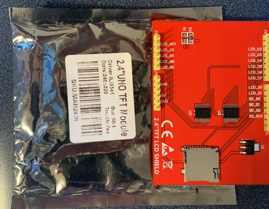
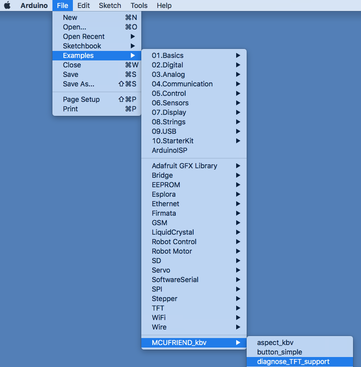
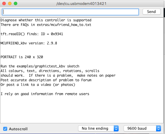
In the previous Article (Part 1), I used an Arduino and two open source libraries to figure out the startup configuration sequence for a low cost 2.4″ TFT from MCUFriend. In Part 2, I will show you how to use that information to make a driver for a PSoC 6 running the Segger emWin graphics library.
The steps that I will follow are:
- Create an Example project for the CY8CKIT-028-TFT from CE223726 and test (make sure the emWin library works)
- Copy the Example and Update Schematic and Pin Out for the MCUFriend Shield.
- Modify the project and initialization code for the ILI9341
- Test
Create an Example Project from CE223726 and Test
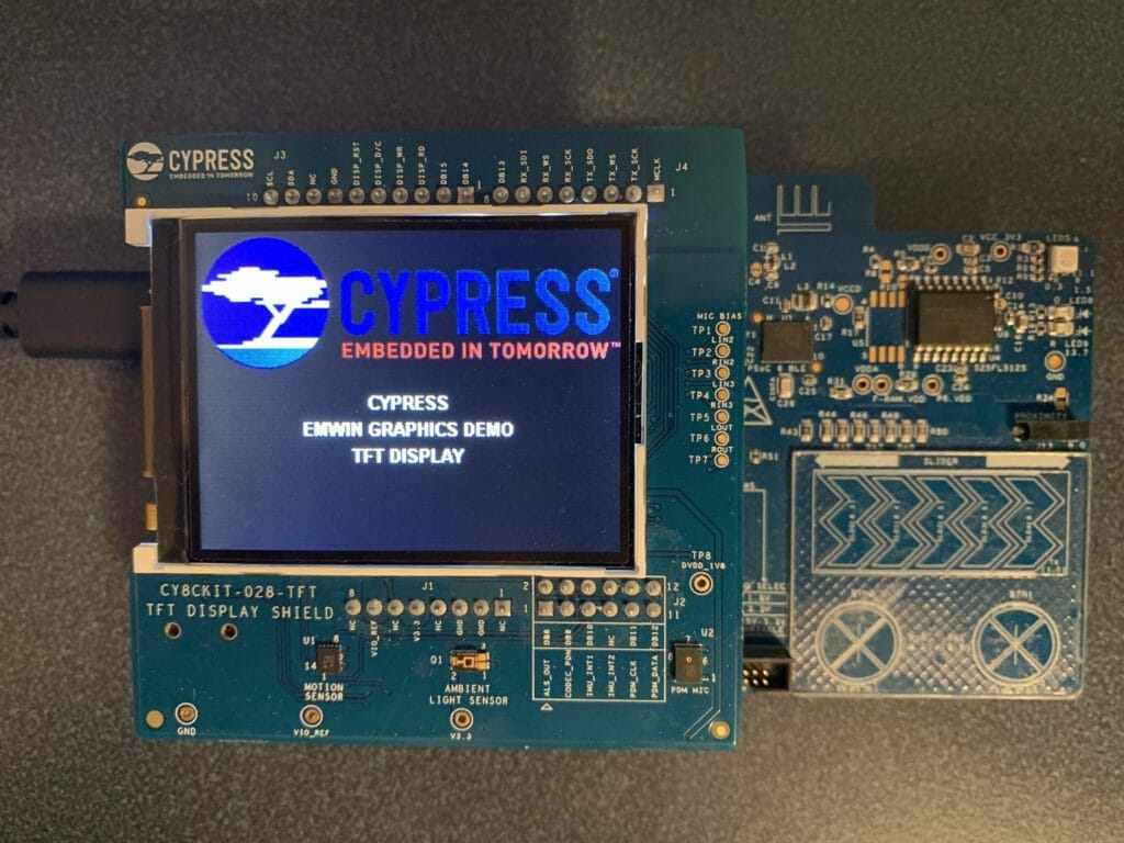
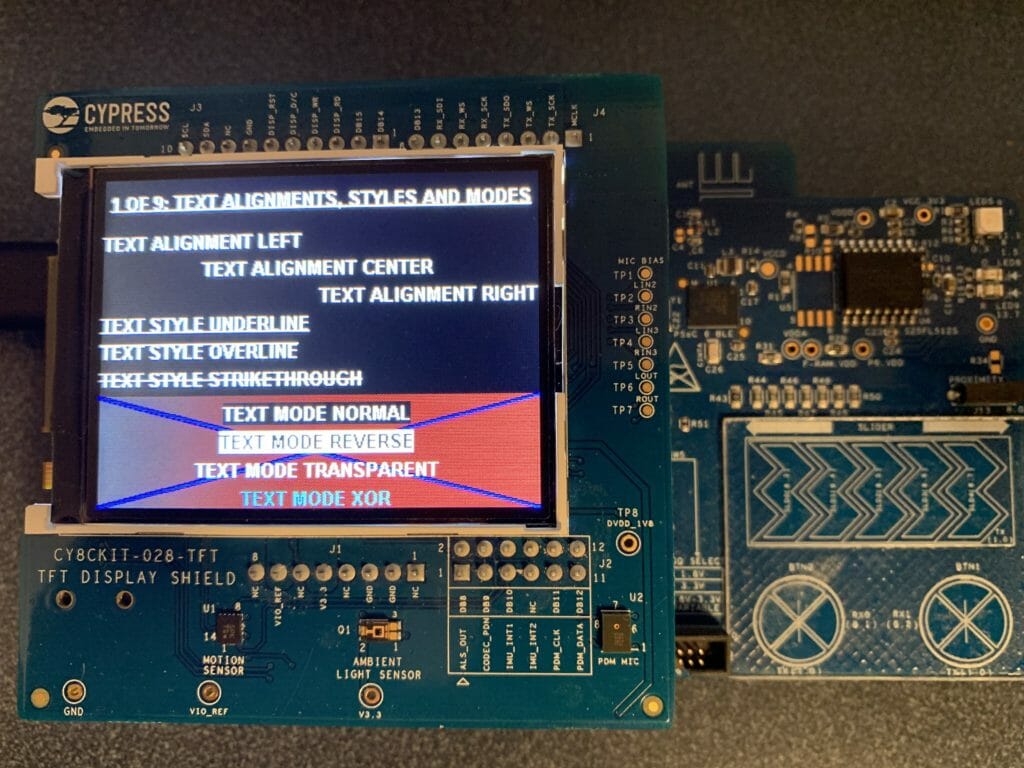
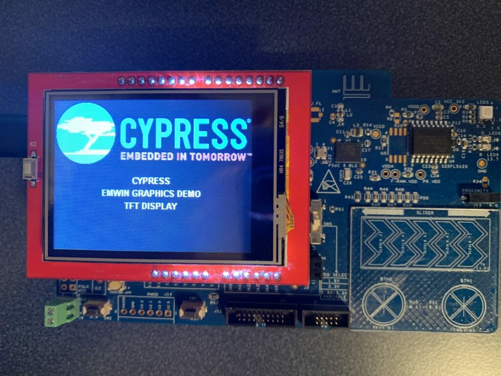
Cypress has delivered a code example for the CY8CKIT-028-TFT shield called CE223726. This CE has all of the hardware connection setup for that shield, plus the integrated emWin middleware and a simple main that just displays 9 different screens.
The shield has a Newhaven 2.4″ 320×240 TFT with a Sitronix ST7789 driver. This display uses the “8080” interface for the display, the same parallel interface as my MCUFriend shield.
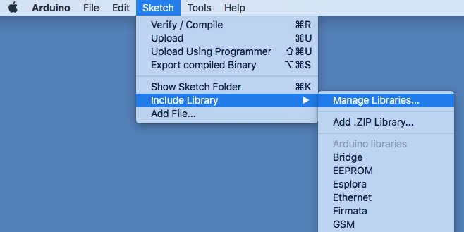
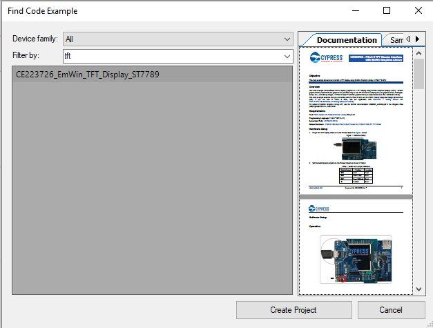
To run the code example, first create a new project from the File->Code Example menu.
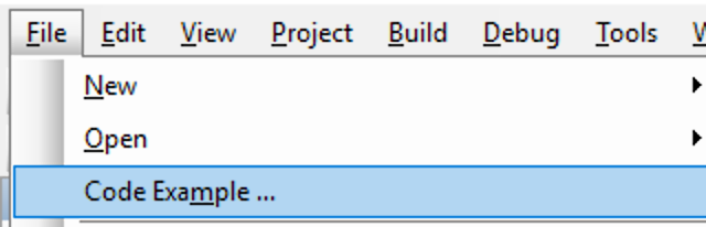
When you filter the list to “tft” by typing in the “Filter by” box you will see CE223726…. select it, then press “Create Project”. If it is not on your computer you need to press the little world symbol to download it.
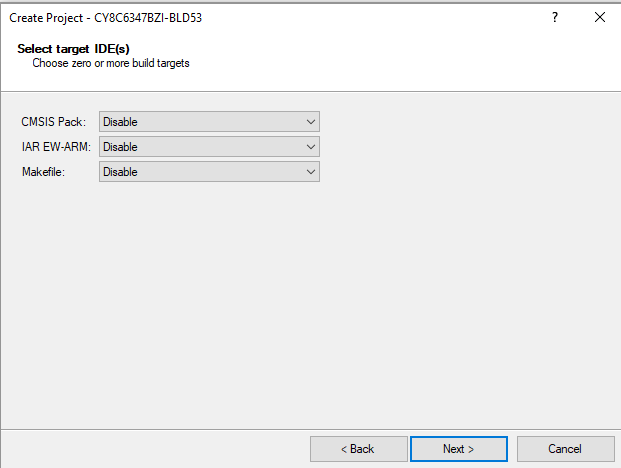
Accept the defaults for the Target IDE by pressing Next.
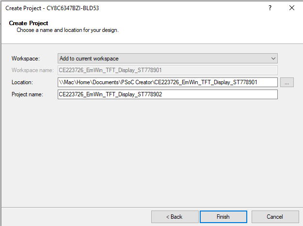
Give the project a sensible name, or accept the default name.
Once you have the project. Program it to make sure that it works.
Copy the Example and Update Schematic and Pin Out
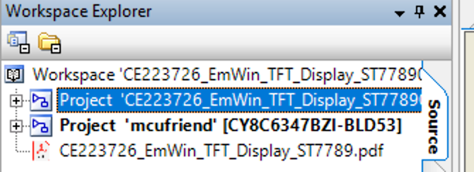
Now that I have the code example project tested, I will make a copy of it to serve as a base for the mcufriend version. In the workspace explorer, select the project then Copy it with ctrl-c. Next, click on the workspace and Paste with ctrl-v. Then, rename the project to “mcufriend”. Here is the workspace explorer after the copy/paste/rename.
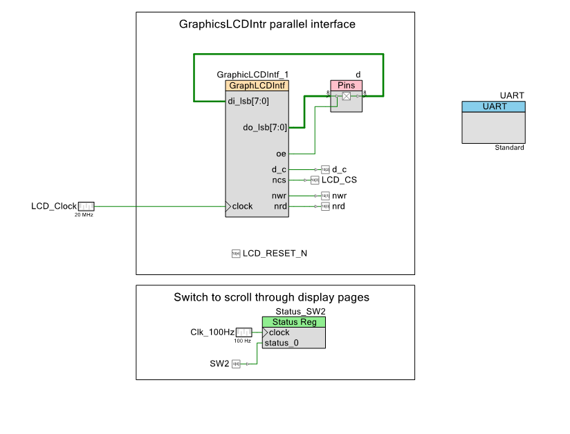
The schematic for this project is interesting. These LCDs use what is called the 8080 interface. It was named 8080 because it is the same 8-bit interface that the old 8080 CPUs used. Instead of using a “bit-banged” interface (like the Arduino implementation) Cypress created a digital component that knows how to write to the screen. Actually this is bad-ass. You can see that the component has D0-D7, Data/Command (D/C), Chip Select, Write (nwr) and Read (NRD). Inside of the block there is a FIFO and a timing circuit that will let you write 8-bits at a time to the screen.
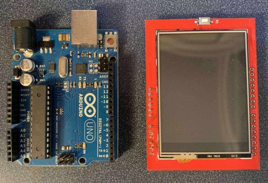
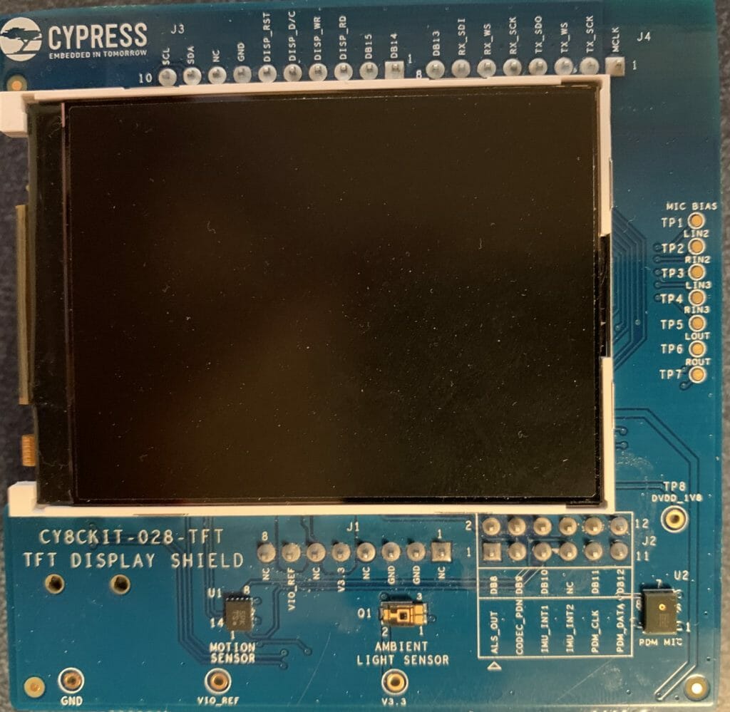
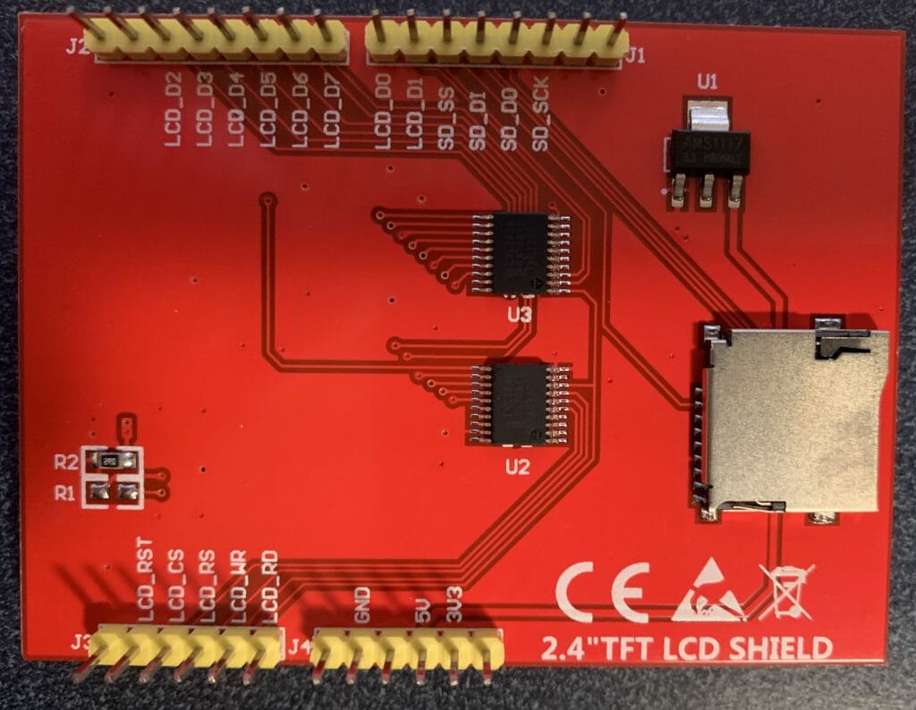
Now on with modifying the project. First, you notice that the 2.4″ TFT shield has a different pin out than the CY8CKIT-028-TFT. Here is a picture of the back of the shield:
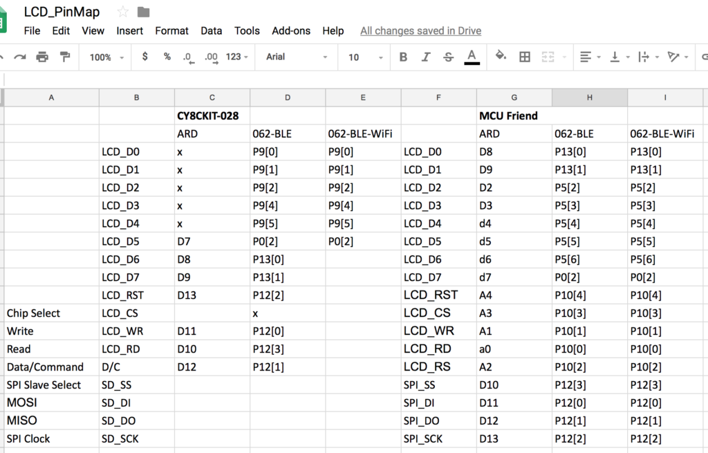
To sort this out I created this pin map. The other thing to notice is that the pin called “LCD_RS” is really the “LCD_C/D” pin. I am not sure why they called it “RS” (well my friend Rajesh figured it out… RS means Register Select). Anyway, here is a picture of the spreadsheet. Another interesting thing to notice is that Cypress choose not to include the Chip Select on the pinout of the shield and in fact it is always selected.
All right, you can see that the pins are different, so, the first step in fixing this project is to remap the pins to match the shield. Open up the Design Wide Resource pin configuration screen from the Workspace Explorer. And assign the Shield Pins to the correct PSoC 6 pins. Notice that I added a UART (which you can ignore)

The next thing that I need to do is update the schematic to reflect the ILI9341 speed. On page 226 of the ILI9341 datasheet you can see that during a write cycle the write pulse needs to be low twrl=15ns and high twrh=15ns and the whole cycle needs to be at least 66ns. For the read cycle the read pulse low trdl=45ns and the trdh=90ns. Unfortunately, I dont know what an “FM” read is versus a “ID” read… so I am going to assume we only do “ID” reads.
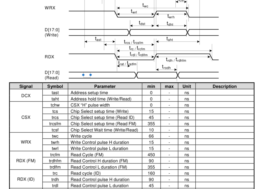
The input clock to the LCD Interface component sets the width of the output write pulse. Specifically, the write output is always low for 1 clock cycle and high for 1 clock cycle. For instance, if your clock is set to 10MHz (also known as a period 100ns) then your write output pulse will be 100ns (low) + 100ns(high). For the read pulse you are given the ability to set the number of clocks for low and high. In the above case of a 10MHz input clock if you set the low to 3 and the high to 5 you would end up with 3*100ns (low) + 5*100ns (high) = 800ns total.
Armed with all of that information, we need to pick 3 numbers. An input clock, the # of read low pulse and the # of read high pulses. The write cycle needs to be at least 66ns so we need a minimum clock frequency of 30MHz which will have a period of 33ns. For the read we need 45ns low and 90ns high and a total of 160ns. This means the whole read cycle needs to be 160ns/33ns=4.8 clock cycles. To achieve this ill select 2 low (for 66ns) and 3 high (99 ns) total 165ns.
Open the schematic, then double click the clock and change its frequency to 30MHz. (notice that I renamed it to LCD_Clock)

Double click the GraphicLCDIntf to update the read transaction low pulse to have 2-clocks and the read transaction high pulse width to be 3-clocks.
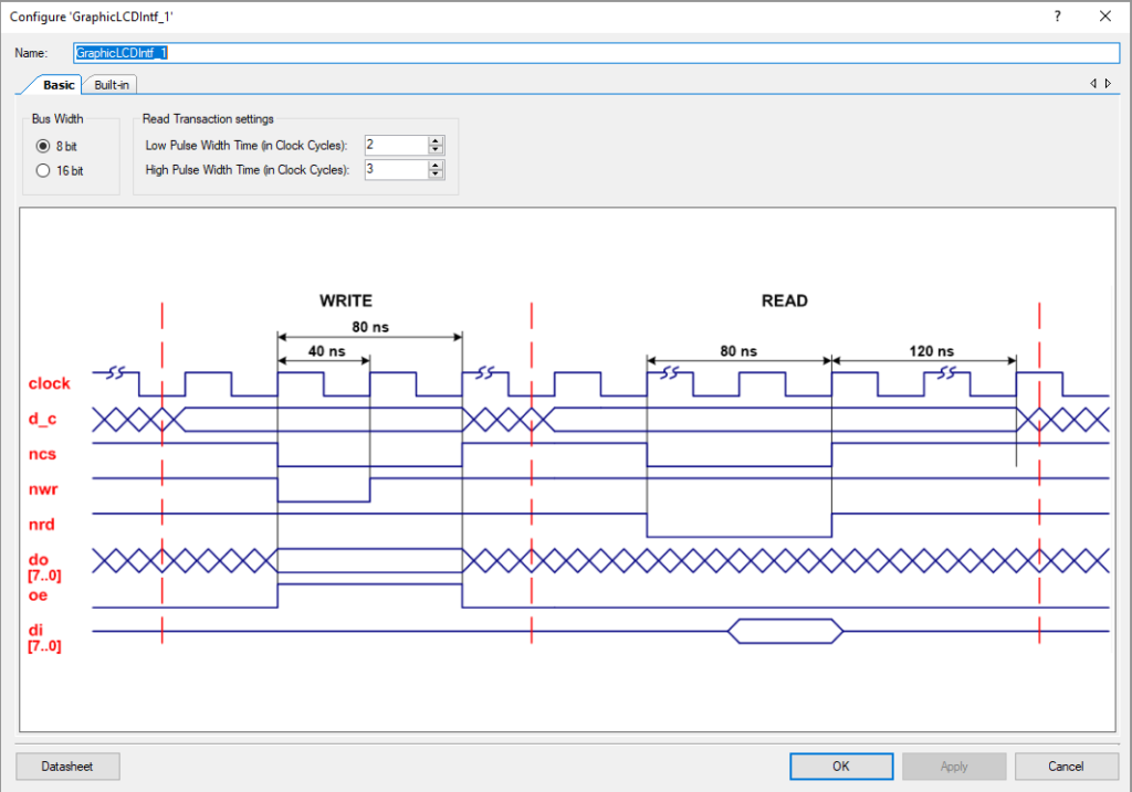
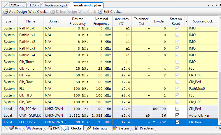
But wait. Why is the pulse width 40ns and 80ns? That means that the input clock is set to 25MHz (40ns period). Well it turns out that is exactly right. But if we typed in 30MHz how did we end up with 25MHz? If you look on the clocks tab of the design wide resources you will find that the source of the LCD_Clock is the Clk_Peri and it is running at 50MHz. When PSoC Creator figures out a clock, it can only choose a whole number divider, also known a 2 to synthesize the LCD_Clk, which means that the output frequency will actually be 25MHz. I am pretty sure that I could move things around and figure out a combination of dividers and clock frequencies to make it work, but that isnt the point today so Ill just move forward.
Modify the Initialization Code
With the schematic and pin out modified, we will turn our attention to the code. There are several changes that need to be made to LCDConf.c
- Create a function called “_InitController_9341” to startup the screen (based on the learning from Part 1)
- Change the name of function “_InitController” to be “_InitController_st7789”
- Update the LCD_X_Config function with the correct orientation and color format
- Update the function “LCD_X_DisplayDriver” to call the correct Initialization function
In order to get the screen going, you need to send the commands/data that we discovered in Part 1. The author of that code had a structure which I like for holding that data. Specifically it is an array of uint8_ts with Command, Length of Data , Data 0-N and on and on. This is exactly the format that I spit out from the Arduino code in the Part 1. Here is the screenshot:
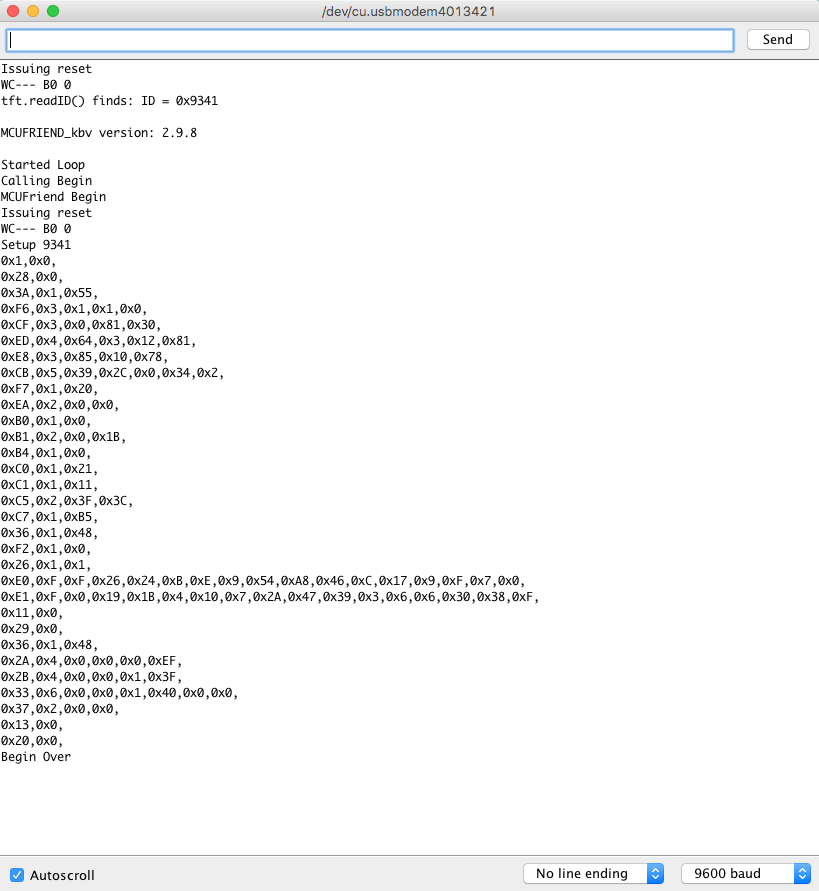
To use this data I create an array (called ILI9341_regValues_2_4 … the same name from the original library.
static const uint8_t ILI9341_regValues_2_4[]  = {        // BOE 2.4"
0x1,0x0,                                  // Software Reset
0x28,0x0,                                 // Display Off
0x3A,0x1,0x55,                            // Pixel Format RGB=16-bits/pixel MCU=16-bits/Pixel
0xF6,0x3,0x1,0x1,0x0,                     // Interface control .. I have no idea
#if 0
0xCF,0x3,0x0,0x81,0x30,                   // Not defined
0xED,0x4,0x64,0x3,0x12,0x81,              // Not defined
0xE8,0x3,0x85,0x10,0x78,                  // Not defined
0xCB,0x5,0x39,0x2C,0x0,0x34,0x2,          // Not defined
0xF7,0x1,0x20,                            // Not defined
0xEA,0x2,0x0,0x0,                         // Not defined
    #endif
0xB0,0x1,0x0,                             // RGB Interface Control
0xB1,0x2,0x0,0x1B,                        // Frame Rate Control
0xB4,0x1,0x0,                             // Display Inversion Control
0xC0,0x1,0x21,                            // Power Control 1
0xC1,0x1,0x11,                            // Power Control 2
0xC5,0x2,0x3F,0x3C,                       // VCOM Control 1
0xC7,0x1,0xB5,                            // VCOM Control 2
0x36,0x1,0x48,                            // Memory Access Control

#if 0
0xF2,0x1,0x0,                             // Not defined
#endif

0x26,0x1,0x1,                             // Gamma Set
0xE0,0xF,0xF,0x26,0x24,0xB,0xE,0x9,0x54,0xA8,0x46,0xC,0x17,0x9,0xF,0x7,0x0,    // Positive Gamma Correction
0xE1,0xF,0x0,0x19,0x1B,0x4,0x10,0x7,0x2A,0x47,0x39,0x3,0x6,0x6,0x30,0x38,0xF,  // Negative Gamme Correction
0x11,0x0,                                 // Sleep Out
0x29,0x0,                                 // Display On
0x36,0x1,0x48,                            // Memory Access Control
0x2A,0x4,0x0,0x0,0x0,0xEF,                // Column Address Set = 239
0x2B,0x4,0x0,0x0,0x1,0x3F,                // Row Address Set  = 319
0x33,0x6,0x0,0x0,0x1,0x40,0x0,0x0,        // Vertical Scrolling Definition
0x37,0x2,0x0,0x0,                         // Vertical Scrolling Start Address
0x13,0x0,                                 // Normal Display ON
0x20,0x0,                                 // Display Inversion OFF
};
Notice that I have ifdef’d out the values that dont do anything. In order to use the array, I create a function called _InitController_9341. It
- Starts the component
- Sends a reset
- Then loops through the datastrcture from above sending Write Commands (GraphicLCDIntf_1_Write8_A0) and Write Data (GraphicLCDIntf_1_Write8_A1)
static void _InitController_9341(void)
{
    /* Start the parallel interface */
    GraphicLCDIntf_1_Start();

    /* Reset - High, Low (reset), High */
    Cy_GPIO_Set(LCD_RESET_N_0_PORT, LCD_RESET_N_0_NUM);
    GUI_Delay(20);
    Cy_GPIO_Clr(LCD_RESET_N_0_PORT, LCD_RESET_N_0_NUM);
    GUI_Delay(100);
    Cy_GPIO_Set(LCD_RESET_N_0_PORT, LCD_RESET_N_0_NUM);
    GUI_Delay(100);

    for(unsigned int i=0;i<sizeof(ILI9341_regValues_2_4);i++)
    {
        GraphicLCDIntf_1_Write8_A0(ILI9341_regValues_2_4[i]);
        printf("Command %02X\r\n",ILI9341_regValues_2_4[i]);
        i=i+1;
        unsigned int count;
        count = ILI9341_regValues_2_4[i];
        for(unsigned int j=0;j<count;j++)
        {
            i=i+1;
            printf("Data %02X\r\n",ILI9341_regValues_2_4[i]);
            GraphicLCDIntf_1_Write8_A1(ILI9341_regValues_2_4[i]);
        }

    }

}
Now we move onto the configuration function. There are several changes that need to be made to it.
- What driver chip you are using?
- What is the bus interface you are going to use?
- What is the format of the RGB Data?
- How do you want the screen setup?
The function call on line 319 configures the driver and the bus interface.
GUIDRV_FlexColor_SetFunc(pDevice, &PortAPI, GUIDRV_FLEXCOLOR_F66709, GUIDRV_FLEXCOLOR_M16C0B8);
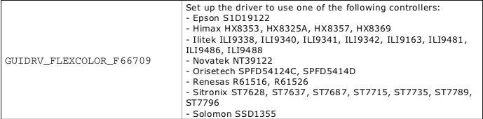
The driver is specified from table 33.42 on page 1193 of the emWin manual. Specifically, you tell it to use GUIDRV_FLEXCOLOR_F66709 which you can see support ILI9341 amongst others.
Then you need to tell what bus interface to use. When we setup the display, we told it that we wanted 16-bit color by sending 0x3A, 0x55. Here is a screen shot from the ILI9341 datasheet.
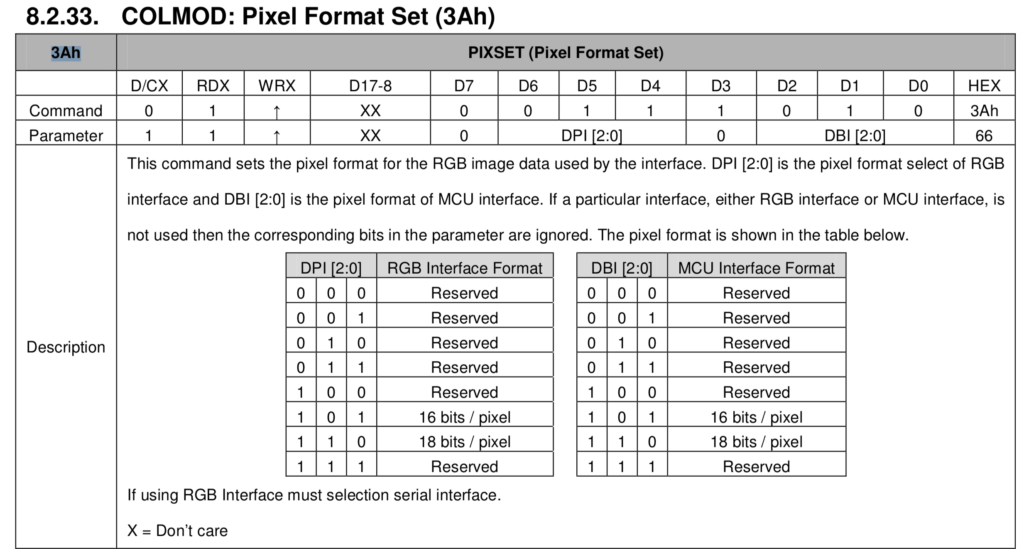
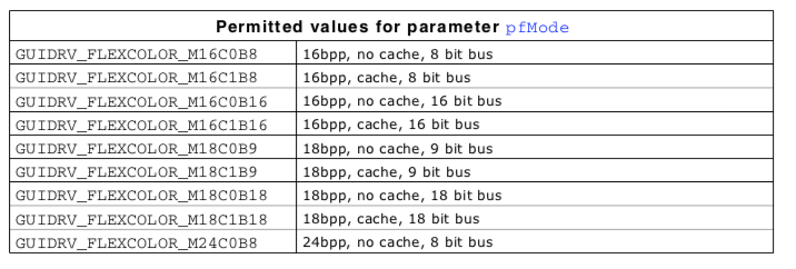
Given that, the last parameter of the driver call is the bus format. So, set the bus width to 16 bits per pixel, 8-bit bus.
GUIDRV_FlexColor_SetFunc(pDevice, &PortAPI, GUIDRV_FLEXCOLOR_F66709, GUIDRV_FLEXCOLOR_M16C0B8);
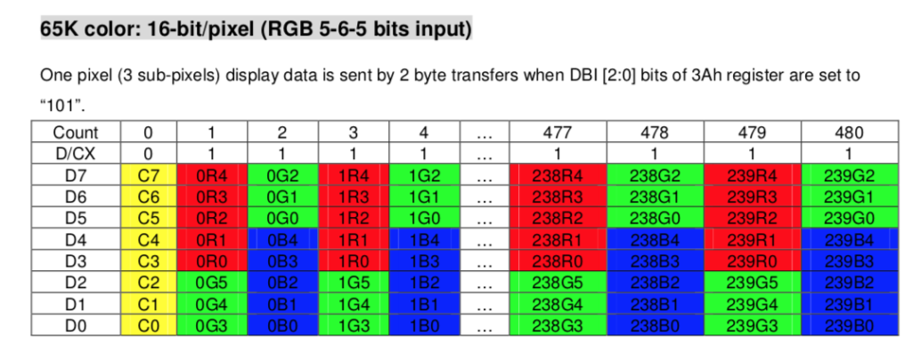
Now you need to tell it what bits mean what color. For this display 16-bit color is encoded at 5-bits of Red, 6-bits of Green and 5-bits of Blue. On Page 65 of the ILI9341 datasheet you can see that we should send 8-bits of command, 5 bits of red, 6-bits of green, 5-bits of blue, then the next pixel.
To tell emWin that, you need to pick GUICC_M565 (see the screen shot below from the Segger emWin documentation)

But it turns out that doesnt work? The blue and green are FLIPPED. How is that possible? As I tried to figure this out I googled a bunch of things… read on the Segger forums etc. All of the normal things. Finally I sent a note to some of my friends at Cypress that went like this:
“There are several possibilities
- There is a bug in emWin
- There is a bug in the ILI9341
- There is a bug in the emWin documentation
- There is a bug in the ILI9341 documentation
- There is a bug in my firmware
- There is a bug in my brain.
- There is a bug in my understanding of the documentation
Personally I bet on #7″
Well it turned out that I was right. It was #7. The Red-Green-Blue order is set by register 36h
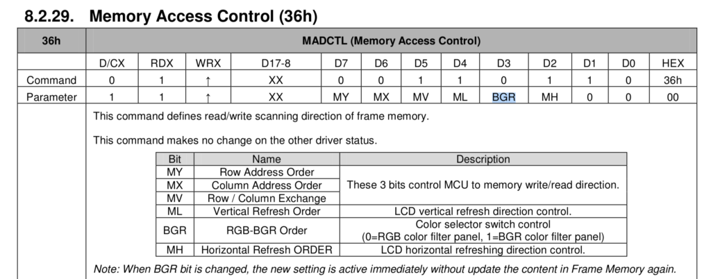
If you recall I copied setup from the Arduino code in Part 1. When I called the setup I wrote 0x48 into that register… that is also known as BGR = 1 or “1=BGR color filter panel”. It turns out that the example of the byte writing order above is just that… and example. How did I figure this out? Simple answer, thank you to Oleksandr in Ukraine for sorting that out for me because I was going out of my mind last night.
Now, the other little nasty part of things is that if I had written BGR=0 it still would not have worked. It turns out that emWin overwrites that bit when it rotates the screen. Why? Who the hell knows. Anyway, here is what Oleksandr says, “In your code in the initialization sequence you set 0x36 register to 0x48 so, BRG mode must be active and GUICC_565 palette must be correct. But FlexColor driver itself writes to the 0x36 register in order to setup display orientation. By default, driver set the BRG bit to zero, activating RGB mode.” Here is a rather vague description of what happens from the emWin documentation. [There is still an error here]
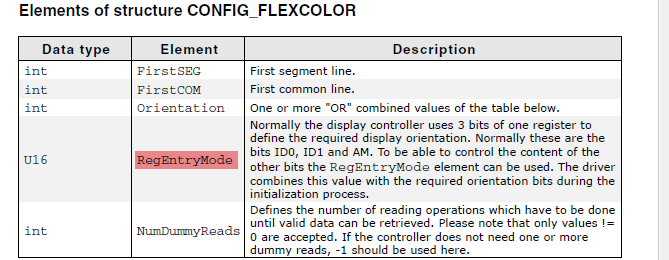
With the color order sorted out, the last thing that I change is the orientation of the display on line 309. Here is the entire configuration function:
void LCD_X_Config(void) {
    GUI_DEVICE * pDevice;
    CONFIG_FLEXCOLOR Config = {0};
    GUI_PORT_API PortAPI = {0};
    //
    // Set the display driver and color conversion
    //
    // GUICC_565
    // GUICC_M565
    pDevice = GUI_DEVICE_CreateAndLink(DISPLAY_DRIVER, GUICC_565, 0, 0);
    //
    // Display driver configuration
    //
    LCD_SetSizeEx    (0, XSIZE_PHYS,   YSIZE_PHYS);
    LCD_SetVSizeEx   (0, VXSIZE_PHYS,  VYSIZE_PHYS);
    //
    // Orientation
    //
    //Config.Orientation   = GUI_MIRROR_Y | GUI_SWAP_XY;
    Config.Orientation   = GUI_SWAP_XY;
    GUIDRV_FlexColor_Config(pDevice, &Config);
    //
    // Set controller and operation mode
    //
    PortAPI.pfWrite8_A0  = GraphicLCDIntf_1_Write8_A0;
    PortAPI.pfWrite8_A1  = GraphicLCDIntf_1_Write8_A1;
    PortAPI.pfWriteM8_A1 = GraphicLCDIntf_1_WriteM8_A1;
    PortAPI.pfRead8_A1  = GraphicLCDIntf_1_Read8_A1;
    PortAPI.pfReadM8_A1  = GraphicLCDIntf_1_ReadM8_A1;
    GUIDRV_FlexColor_SetFunc(pDevice, &PortAPI, GUIDRV_FLEXCOLOR_F66709, GUIDRV_FLEXCOLOR_M16C0B8);
}
In the LCD_X_DisplayDriver function I will simply call the correct initialization function… the one we just created … called _InitController_9341
int LCD_X_DisplayDriver(unsigned LayerIndex, unsigned Cmd, void * pData) {
    int r;

    GUI_USE_PARA(LayerIndex);
    GUI_USE_PARA(pData);

    switch (Cmd) {
        case LCD_X_INITCONTROLLER: {
            //
            // Called during the initialization process in order to set up the
            // display controller and put it into operation. If the display
            // controller is not initialized by any external routine, this needs
            // to be adapted by the customer...
            //
            // ...
            _InitController_9341();
            return 0;
        }
        default:
            r = -1;
    }
    return r;
}
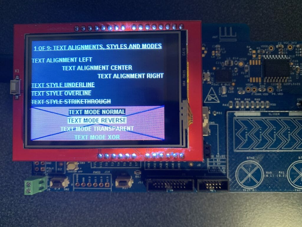
Test
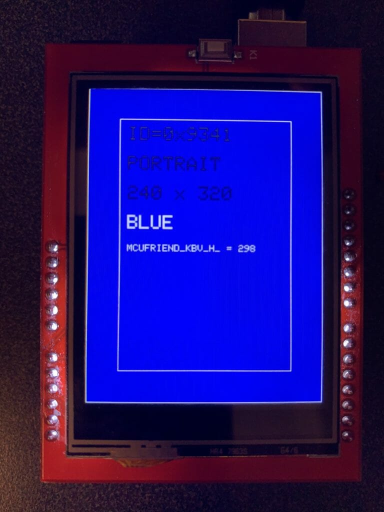
Finally a program and test… and lookey here… it works:
You can find all of these projects on my github site: https://github.com/iotexpert/MCUFriend or clone it with git clone git@github.com:iotexpert/MCUFriend.git
Embedded Graphics Index
Embedded Graphics
Embedded Graphics Overview
TFT Displays & Drivers
TFT Controllers
PSoC 6 + Segger EmWin + MCUFriend 2.4" TFT - Part 1
PSoC 6 + Segger EmWin + MCUFriend 2.4" TFT - Part 2
MCU Friend 3.5" Identification