FreeRTOS Command Line Interface (CLI)

Summary

In a previous article, I gnashed my teeth about my implementation of the FreeRTOS FAT SL.  Specifically, I wasn’t very happy about my command line interface.  What I did was cheap and easy, which sometimes is a good thing, but given that the FreeRTOS Command Line Interface comes as part of the FreeRTOS installation, it sure seemed like that would have been a better way to go.  Now that I have finished the FreeRTOS Command Line Interface implementation, I am not totally in love with how it works.  But, it was worth the time to figure it out. In this article In this article I will make a copy of the PSoC Real Time Clock Project, add the FreeRTOS Command Line Interface and explain how the CLI works.  In the next article I will give the project the ability to set and read the time from the RTC component in the PSoC.

While I was working on the implementation I discovered that the example code used FreeRTOS_write and FreeRTOS_read which depend on a Peripheral Driver Library (don’t confuse that with the Cypress Peripheral Driver Library) and are part of FreeRTOS+IO.  I did very a very simple implementation of those commands to make the FreeRTOS Command Line Interface work, and I will talk more about the FreeRTOS+IO in a future article.

FreeRTOS Command Line Interface

The FreeRTOS Command Line Interface is pretty straightforward to use.  Basically you:

  1. Integrate FreeRTOS_CLI.h and .c into your project
  2. Create one or more command functions and register them for use by the CLI by calling FreeRTOS_CLIRegisterCommand
  3. Read input from the terminal UART into a buffer
  4. Call the CLI (when the users presses enter) and display the output

Integrate FreeRTOS Command Line Interface C Files

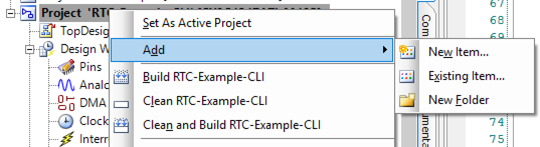
I start this whole thing by copying the project “RTC-Example” from the previous article into a new project called “RTC-Example-CLI”.  Inside of the directory FreeRTOSv9.0.0/FreeRTOS-Plus/Source/FreeRTOS-Plus-CLI you will find FreeRTOS_CLI.h and FreeRTOS_CLI.c.  These two files have all of the FreeRTOS Command Line implementation.  To make this work I copied them into my project, and then did “Add –> Existing Item” to get PSoC Creator to make them part of the project.

Integrate FreeRTOS Command Line Interface C Files

Create a Command

To use the FreeRTOS Command Line Interface you need to create one or more functions which the CLI will then callback when it detects that the user has typed that command.   Each command takes three input parameters

  1. A pointer to a character buffer where the command can store text to be printed on the screen
  2. The size of that buffer
  3. A pointer to a character buffer that holds the whole string that the user typed

The function is then responsible for

  1. Doing the command
  2. Writing some output into the output buffer (up to the length of the buffer)
  3. Returning pdFALSE (if the command has completed writing the output) or pdTRUE (if it needs to do some more processing or more output)

For example if you want to create a command to clear the screen you would create a function called “clearCommand”  That command would

  1. Ignore the pcCommandString (there are no parameters)
  2. Keep track of the number of characters written into the buffer using a static int
  3. Copy the VT100 Clear String (AKA “\033[2J\033[H”) into the output buffer
  4. Null terminate the output string
  5. If you wrote less characters than the string then return pdTrue
  6. Otherwise return false
/*****************************************************************************\
 * Function:    clearCommand
 * Input:       char *pcWriteBufer,size_t xWriteBufferLen,const char *pcCommandString
 * Returns:     BaseType_t
 * Description: 
 *     This function clears the screen. It is run by the CLI interpreter
\*****************************************************************************/

BaseType_t clearCommand( char *pcWriteBuffer,size_t xWriteBufferLen, const char *pcCommandString )
{
    (void)pcCommandString;
    static int processed = 0;
    
    char *clearScreen = VT100_CLEARSCREEN;
    // Only allowed to write up top xWriteBufferLen bytes ... 
    strncpy(pcWriteBuffer,&clearScreen[processed],xWriteBufferLen-1);
    pcWriteBuffer[xWriteBufferLen-1]=0;

    processed = processed + xWriteBufferLen-1;
    if(processed < (int)strlen(clearScreen))
        return pdTRUE;
    
    processed = 0;
    return pdFALSE;
}

Once you have created the command function you then need to register it with the FreeRTOS Command Line Interface.  To do that you create a structure of type “CLI_Command_Definition_t” which has 4 members.

  1. The ascii string which the user can type to trigger the command
  2. The help message
  3. A function pointer to the command function
  4. The number of arguments that the CLI should accept
    static const CLI_Command_Definition_t clearCommandStruct =
    {
        "clear",
        "clear: Clear Screen by sending VT100 Escape Code\n",
        clearCommand,
        0
    };

Finally you need to register the command.  You should be aware that this function uses malloc.

FreeRTOS_CLIRegisterCommand( &clearCommandStruct );

Call the CLI and Display

On the FreeRTOS Command Line Interface webpage they provided a sample task to handle the command line interpreter.  I copied this task into my project and then made a few little changes.

  1. My Mac sends a ‘\r’ when you press the return key so I changed line 164 to reflect that
  2. My Mac sends 0x7F when you press the “Delete” key.  So I changed the ‘\b’ (aka backspace) to be 0x7F aka “del”
  3. I fixed the stupid ‘\r\n’ stuff

One of the great annoyances in the world is the way that line breaks in text files and terminals are handled.  It is typical in “unix” to use just a newline “\n”.  However, in “DOS” it is typical to use a carriage return/newline “\r\n”.  All over FreeRTOS it uses DOS mode.  I typically like to use unix mode… so you will find that I made that changes in the FreeRTOS CLI code.

The cliTask function does a number of things.

  1. Initializes the IO System, RTC and Command Line Interface (lines 154-163)
  2. Gets 1 character from the UART using FreeRTOS_read
  3. If the character is a carriage return (\r) then it calls the CLI until there is no more output (lines 167-196).   Remember that when you implement a command function for the CLI, if you return pdFALSE it means that you have no more output, and if you return pdTRUE then you have more output.
  4. If the character is the delete key (0x7F) then erase the character from the input buffer)
  5. Otherwise add it to the input buffer… assuming that you still have room.  (lines 227-232)
/*****************************************************************************\
* Function:    cliTask
* Input:       void *arg  ... unused
* Returns:     void
* Description: 
*     This function is the inifite loop for the command line intepreter.. it
*     reads characters using the FreeRTOS_read function then sends them to the
*     cli when there is a \r 
\*****************************************************************************/
void cliTask(void *arg)
{
(void)arg;
char pcOutputString[ MAX_OUTPUT_LENGTH ], pcInputString[ MAX_INPUT_LENGTH ];
int8_t cRxedChar, cInputIndex = 0;
BaseType_t xMoreDataToFollow;    
FreeRTOS_open( (const int8_t *)"/uart",0 );
clearScreen();
#define INTRO_STRING "Command Line & RTC Demo\n"
FreeRTOS_write(0,INTRO_STRING,strlen(INTRO_STRING));
RTC_Start();
FreeRTOS_CLIRegisterCommand( &clearCommandStruct );	
FreeRTOS_CLIRegisterCommand( &setTimeCommandStruct );	
FreeRTOS_CLIRegisterCommand( &timeCommandStruct );	
while(1)
{
FreeRTOS_read( 0, &cRxedChar, sizeof( cRxedChar ) );
if( cRxedChar == '\r' )
{
/* A newline character was received, so the input command string is
complete and can be processed.  Transmit a line separator, just to
make the output easier to read. */
FreeRTOS_write(0,&cRxedChar,1);
/* The command interpreter is called repeatedly until it returns
pdFALSE.  See the "Implementing a command" documentation for an
exaplanation of why this is. */
do
{
/* Send the command string to the command interpreter.  Any
output generated by the command interpreter will be placed in the
pcOutputString buffer. */
xMoreDataToFollow = FreeRTOS_CLIProcessCommand
(
pcInputString,   /* The command string.*/
pcOutputString,  /* The output buffer. */
MAX_OUTPUT_LENGTH/* The size of the output buffer. */
);
/* Write the output generated by the command interpreter to the
console. */
FreeRTOS_write( 0, pcOutputString, strlen( pcOutputString ) );
} while( xMoreDataToFollow != pdFALSE );
/* All the strings generated by the input command have been sent.
Processing of the command is complete.  Clear the input string ready
to receive the next command. */
cInputIndex = 0;
memset( pcInputString, 0x00, MAX_INPUT_LENGTH );
}
else
{
/* The if() clause performs the processing after a newline character
is received.  This else clause performs the processing if any other
character is received. */
if( cRxedChar == 127 ) // delete character
{
FreeRTOS_write(0,&cRxedChar,1);
/* Backspace was pressed.  Erase the last character in the input
buffer - if there are any. */
if( cInputIndex > 0 )
{
cInputIndex--;
pcInputString[ cInputIndex ] = '\0';
}
}
else
{
/* A character was entered.  It was not a new line, backspace
or carriage return, so it is accepted as part of the input and
placed into the input buffer.  When a \n is entered the complete
string will be passed to the command interpreter. */
if( cInputIndex < MAX_INPUT_LENGTH )
{
FreeRTOS_write(0,&cRxedChar,1);
pcInputString[ cInputIndex ] = cRxedChar;
cInputIndex++;
}
}
}
}
}

As always you can find all of this code on the IoT Expert GitHub website or your can git clone git@github.com:iotexpert/PSoC-FileSystem.git

JST Connector Crimping Insanity

[Edit] Since I published this article, Tom Nardi at Hackaday wrote an article entitled “The unnecessary? Art of Connector Crimping” about my article where he pointed out that I am not the first person to come to that conclusion.  He made reference to several useful things

  1. JST is not a Connector
  2. BRADLEY GAWTHROP: WHAT YOU NEED TO KNOW ABOUT WIRING

[Edit] The Wikipedia article on JST has a nice table.

Summary

Last week I was using a CY8CKIT-062-BLE PSoC 6 development kit with a Digilent PMOD-HB5 connected to the PMOD port.  Specifically, I was using the PMOD HB5 as a solid state switch to drive a higher voltage, higher current than the GPIO on the PSoC 6 can drive.  In order to do this I needed to connect to the “6-pin JST connector for direct connection” which is on the right side of the board in the picture below.

Digilent PMOD HB5

But, what I might ask, is a JST Connector?  And, how might you make a connection to it.  Well, this where the insanity starts.  The first thing that you will discover is that “JST” stands for Japan Solderless Technology and that they make about 50,000 different types of connectors.  The next thing that you will discover is that all around the internet on the maker websites you will find people referring to connections as “JST” and acting like there is only one type of JST connector.  Then you will discover that there are tons of youtube videos that “show” you how to crimp JST connectors, and that most of them are absolute crap, particularly if you are 50 years old can barely see the freaking crimp connectors.  Finally, you will discover that there are a boatload of crimping tools that range in price from $10 (for a crap pair of pliers) to $500 (for the OEM JST Crimpers)

For this article I am going:

  1. Tour the common version of the JST connectors, where they are used.
  2. Consider not crimping
  3. Show pictures of a proper crimp
  4. Show some JST crimping tools
  5. Take you through my crimping procedure – which seems to work
  6. Some other videos/resources

Honestly the whole thing is pretty annoying.  The crimps are a bit hard to make and there is this inherent assumption everywhere that you should have just “known” how to do this.

I will also observe that the “JST” problem extends to some other crimp connectors including “Molex” and “Dupont” (which has a crazy history).  I will write about these other two types later on.

The JST Connector Series

Series Pitch Wire Connector Use
PH 2.0 24 JST PH Connector Digilent PMOD HB5
SM 2.5 28 JST SM Connector Adafruit Adafruit NEOLED
SH 1.0 28 JST SH Connector Spark Fun QWIIC 
XH 2.5 22 JST XH Connector Some batteries
ZH 1.5 26 JST ZH

Consider not Crimping

The first thing that I will say about the crimping process is that you should consider not doing it.  It is possible that purchase pre-crimped wires which will then easily slip inside of the connector housing to create almost any combination you might want.  Here is a pile of the the raw wires with crimps on one end:

JST PH Connector

And here are some that are pre-made into 6-pin connections.

JST Connector

A Good Crimp

So… you really want to make your own crimps?  OK.  Before I tell you HOW to do a good crimp, I want to show you what you are trying to do.  When you buy the crimp connectors, they will come on a metal strips which are meant to go through a machine that automatically crimps wires in China (obviously we are going to do it manually).

JST Connector

Each crimp connector has two sets of wings, which you will bend during the process.  One set holds the wire and the other holds the insulation.  Here is a zoom of some of the connectors where you can see the wings.

JST Connector

In the picture below you can see that there are two sets of wings.  The set in the middle crimps the raw wire.  The set that is near the strip is for the insulation.

JST Connector

Here is a picture of what we are trying to achieve with the crimp.  You can see that the inner crimp grabs all of the wires and the outer crimp grabs the insulation on the wire.

JST Connector

Once you have the wires crimped they will snap into a plastic housing that gangs them together.  In the picture below you can see that on the backside of the crimp connector there is a little piece that is bent up.  That will snap under the little plastic tab on the housing.  (it is a 2-pin housing)

JST Connector

In this picture you can see another view of the piece of metal that is bent up to grab the plastic.

JST Connector

Once you stick the crimp connector into the housing it will look something like this.  When you push the wire into the housing you will get a very satisfying little click (assuming you haven’t destroyed the crimp connector metal too much)

JST Connector

Crimping Tools

I bought a range of tools, but these tools from a Japanese company called “Engineer” seemed to be the best.  These tools are less “efficient” because you have to crimp twice, once for the wires and once for the insulation, but they seem to be easier not to screw up with.  The difference between PA-09 and PA-20 is the range of crimp sizes that you can do.

Engineer PA-20 & PA-09

I bought these two tools from Amazon for about $20… and they crimp both sets of wings at one time… but I have not had good luck with them.

IWISS Crimper

The actual JST crimper is really cool, but it had better be for $470.  I haven’t tried it because the Engineer PA-09 worked so well.  It can crimp both sets of wings at the same time and automatically positions the crimp connector to the exact right place.  But it also only works for one type of connector, in this case the JST-PH

JST WC-240

JST Connector Crimping Procedure

I would not say that my process is canonical, but it works.

(1) Start by stripping the end of your wire, then giving it a little twist.  I use a stripping tool called a “Knipex 12 42 195”.  The strip should be about 2-3mm

Knipex Stripper

(2) Then break off a crimp connector from the strand.  Hold it in your left hand and stick the wire wings into the 1.6mm section of the tool.  The wings should point into the crimper (look at the picture) so that when you crimp, that they bend back on themselves.  You want to make sure that the outer insulation wings are not in the crimper, meaning we are only going to crimp the inside wings on the first crimp.

JST Connector

Here is a picture where you can see that things are all lined up.

JST Connector

Dont crimp yet, but push down a little bit to hold the crimp connection in place while you use your left hand to pick up the wire.

JST Connector

(3) Insert the wire into the crimp connection.  The plastic insulation should end at the edge of the crimper (it should not stick into the connection).  In my experience, the insulation is too big to go into the connection and the side of the crimp tool keeps it from going in.

  JST Connector

(4) Then crimp it… and you will have something that looks like this.  You can see that the strands of the wire are under the newly folded wings… and the outer wings are still open.

JST Connector

(5) Use the end of the crimper to bend the out wings in just a little bit so that it can fit into the crimp tool.  Just make them so that they are parallel.

JST Connector

(6) Next put it in the crimp connection into the 1.9mm slot (from the other side) & crimp.

JST Connector

Now you should have a crimped connection

And here is a short video of me completing a JST Connector crimp

In my experience the thing that go wrong when crimping a JST Connector are

  1. I over crimp and bend the crap out of the connection
  2. I strip either too much or not enough wire
  3. I dont push the wire in far enough, which ends up with me not crimping insulation.


IOT Expert 2017 Year in Review and 2018 Goals

Summary

I have been struggling a little bit to write the 2017 year end review.  The basic reason is that although I made a boatload of progress on the website, it has been feeling a little bit like a job.  That being said, I made significant progress on posts, visits, unique visitors and page views.  Also, with the help of Yakob we released a major facelift to the look and feel of the website.

Here is a summary of the data.

Metric 2016 2017 Multiple
Visitors 16156 64493 4.0
Visits 54582 262299 4.8
Page Views 207551 595179 2.9
Posts 76 90 1.2

However, you might notice that I don’t have the goals for those metrics in the table, which as you might guess, means that I was far away from where I was hoping to get.

2017 Data

The data from the web server looks really good with generally increasing numbers of visits and visitors.  For the next year I want to get google analytics going again.

2017 Goals

I copied the following text directly from my article last year called IoT Expert Year in Review 2016 and 2017 Goals

For 2017 my goals fall into three broad categories.  First, I want to continue creating (hopefully) interesting, high-quality IOT engineering content [I think I did pretty well here].  To that end I would like to:

  1. Achieve 2x/week posts and hit 104 posts for the year. [I completed 90 posts… which in hindsight is pretty good, but didn’t meet my goal]
  2. Create a new video series and post 12 videos [I did not make any progress on this idea]

In addition to the new content, I would like to improve the accessibility of my website by

  1. Deploying a mailing list [Not Done]
  2. Automatically connecting to Twitter [Not Done]
  3. Automatically connecting to Facebook [Not Done]
  4. Developing a Linked-In strategy [Not Done]
  5. Fixing my release process to use best practices for all meta-data [Done]

such that I achieve

  1. 10x User Traffic (15,594 –> 69,493)
  2. 10x Twitter followers on @askiotexpert (50–>146)
  3. 10 Google keywords where www.iotexpert.com is a first page hit

Lastly, I want to update and deploy a new brand for iotexpert including logo’s, web page headers, Facebook covers, etc. [Done]

2018 Goals

For 2018, I think that I will strive to make it more fun for myself, with the goal of publishing 1/week.  I hope to create articles on:

  • WICED WiFi
  • WICED Bluetooth
  • PSoC 6
  • RTOS (Linaro, MBEDOS, Apache Newt)
  • FileSystem

I do not think that I will set specific goals for the rest of the data and we will just have to see what happens.