PSoC 6 Low Power MCWDT

Summary

In the last article I wrote about using the PSoC 4 Watch Dog Counter as a deep sleep timer.  It seems kind of obvious that I should probably mostly do PSoC 6 articles.  So, in this article, Ill show you how to use the PSoC 6 Low Power MCWDT as a deep sleep timer.  What is a “MCWDT?”, well, the MC stands for Multi-Counter.  And as best I can tell, is exactly the same as the PSoC 4 WDT, except there are two of them in the PSoC 63 instead of the 1 in the PSoC 4.  There is also a dedicated 16-bit WDT (which I will write about in a few days).

Specifically in this article I will show you:

  • The PSoC 6 Low Power MCWDT Multi-Counter WatchDog Timer
  • How to configure the Low Frequency Clock Sources
  • Configuring the Clk_LF Source in Firmware
  • Overall Project Schematic Configuration for the PSoC 6 Low Power MCWDT
  • Configuring the Interrupts
  • Configuring the PSoC 6 Low Power MCWDT
  • The PSoC 6 Low Power MCWDT Firmware

The Multi-Counter WatchDog Timer (MCWDT)

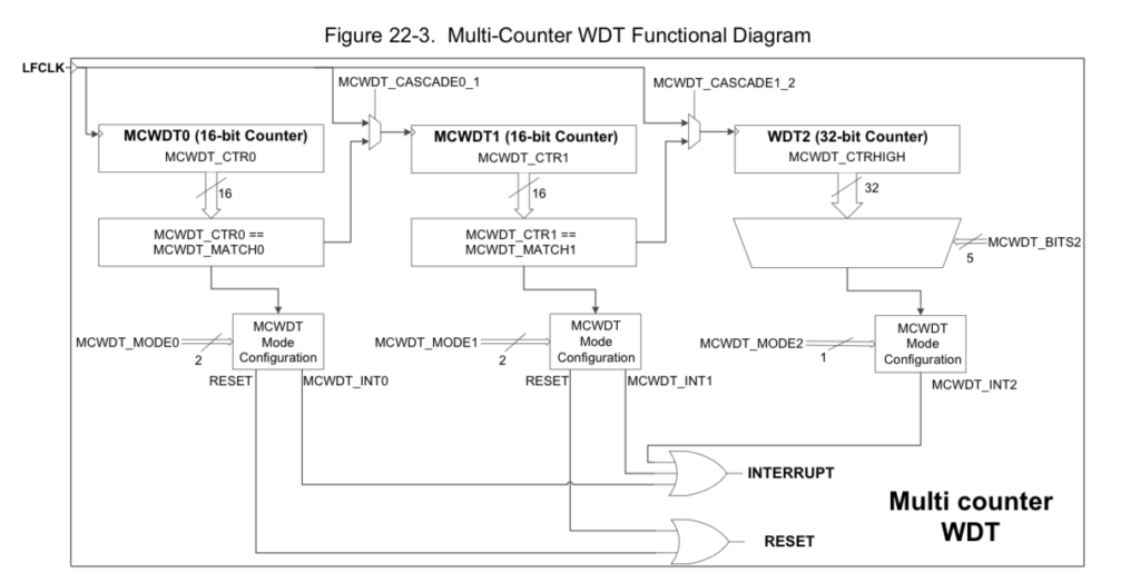
The PSoC 6 Low Power MCWDT is almost exactly the same as the PSoC 4 WDT – except it is in 40nm instead of 130nm.  It has 2x 16-bit counters and 1x 32-bit counter.  The three counters can be cascaded to create long period timers.  Each counter can be configured to clear on match, or free-run.  Each counter can also be configured to cause a device reset if the interrupt is not processed.  The MCWDT works in Active, Low Power Active, Sleep, Low Power Sleep and Deep Sleep power modes.

The design intent is that one MCWDT would be “assigned” to each of the MCUs (i.e. the M4, M0+), but that is not required.  The picture below is a snapshot from the PSoC 63 TRM and explains pretty well how one of the PSoC 6 Low Power MCWDT work.

PSoC 6 Low Power MCWDT

Low Frequency Clock Sources (CLK_LF)

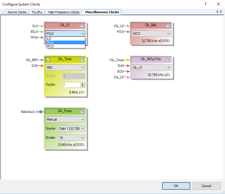
From the picture above you can see that the MCWDT uses the LFLK as the source clock for the counters.  Fortunately or unfortunately there is an inconsistency in the PSoC 63 TRM and PSoC Creator.  The PSoC Creator team decided to unify the names of all of the clocks by calling them all “Clk_*”.  Which is inconsistent with the TRM which calls it “LFLK”.  The LFCLK in the TRM is called the “Clk_LF” in the PSoC Creator GUIs and it is called “CLK_LF” or “ClkLf” in the firmware (confused yet?).  If not then you should be as I was the first time I saw it.

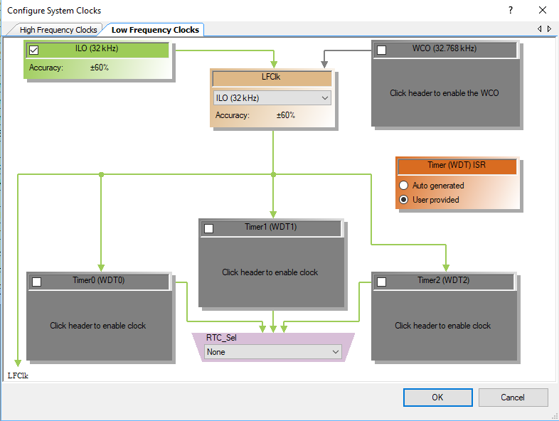
The Clk_LF can be driven by one of three source oscillators.  The PILO, ILO or the WCO.  Look at the upper left hand box where I have pulled down the selection menu.

PSoC 6 Clock Configuration

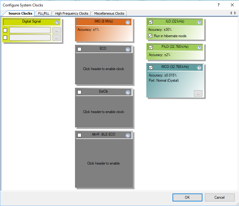
But what is WCO, PILO and ILO?  These are clock sources which you can select the Clk_LF clock source on the “Source Clocks” page.  It can be:

  • The Internal Low Speed Oscillator (ILO) which is a super low power 32KHz RC Oscillator (but not very accurate)
  • The Precision Internal Low Speed Oscillator (PILO) is a more accurate, trim-able RC? oscillator, and presumably higher power (though I don’t know how much).
  • The Watch Crystal Oscillator (WCO) which is a very accurate crystal oscillator that gives you accurate timing at a higher power cost.

With the “Configure System Clocks” window in the DWR you can configure the behavior of the Clock Sources.  Notice that I have turned on all three of the Clock sources (ILO, PILO and WCO) something which you probably wouldn’t actually do.

PSoC 6 Source Clock Configuration

When you click those buttons, PSoC Creator will create a function called “ClockInit” in the file “cyfitter_cfg.c” that is called by the PSoC startup code (and runs before your main() ).  You can see that the firmware enables the PILO and WCO (as well as the ILO which is on by default)

static void ClockInit(void)
{
	uint32_t status;

	/* Enable all source clocks */
	Cy_SysClk_PiloEnable();
	Cy_SysClk_WcoEnable(900u);
	Cy_SysClk_ClkLfSetSource(CY_SYSCLK_CLKLF_IN_PILO);

	/* Configure CPU clock dividers */
	Cy_SysClk_ClkFastSetDivider(0u);
	Cy_SysClk_ClkPeriSetDivider(1u);
	Cy_SysClk_ClkSlowSetDivider(0u);

Configuring the Clk_LF Source in Firmware

You can also configure the Clk_LF sources in your firmware.  In the firmware below, I check to see if the WCO is running.  If it is, then I set it to be the source of the Clk_LF.  If it is not running, then I try to start it.  And, finally, I print out the current source of the Clk_LF.

    // Is the Watch Crystal Osc running?
    if(Cy_SysClk_WcoOkay())
    {
        printf("Switching ClkLf to WCO\n");
        Cy_SysClk_ClkLfSetSource(CY_SYSCLK_CLKLF_IN_WCO);
    }
    else
    {
        printf("WCO Not functioning attempting a start\n");
        Cy_SysClk_WcoEnable(0); // come back immediately
        for(int i=0;i<100;i++) 
        {
            CyDelay(10);
            if(Cy_SysClk_WcoOkay())
            {
                printf("Suceeded in starting WCO in %dms\n",i*10);
                Cy_SysClk_ClkLfSetSource(CY_SYSCLK_CLKLF_IN_WCO);
                break;
            }
        }
        if(!Cy_SysClk_WcoOkay())
        {
            printf("Unable to start WCO in 1000ms\n");
        }
    }
                     
    // What is the clock source of the ClkLf?
    switch(Cy_SysClk_ClkLfGetSource ())
    {
        case CY_SYSCLK_CLKLF_IN_ILO:
            printf("Clk LF = ILO\n");
            break;
        case CY_SYSCLK_CLKLF_IN_ALTLF:
            printf("Clk LF = ALTLF\n");
        break;
        case CY_SYSCLK_CLKLF_IN_PILO:
            printf("Clk LF = PILO\n");
        break;
        case CY_SYSCLK_CLKLF_IN_WCO:
            printf("Clk LF = WCO\n");
        break;
    }

Overall Project Schematic Configuration

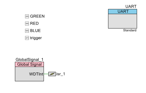
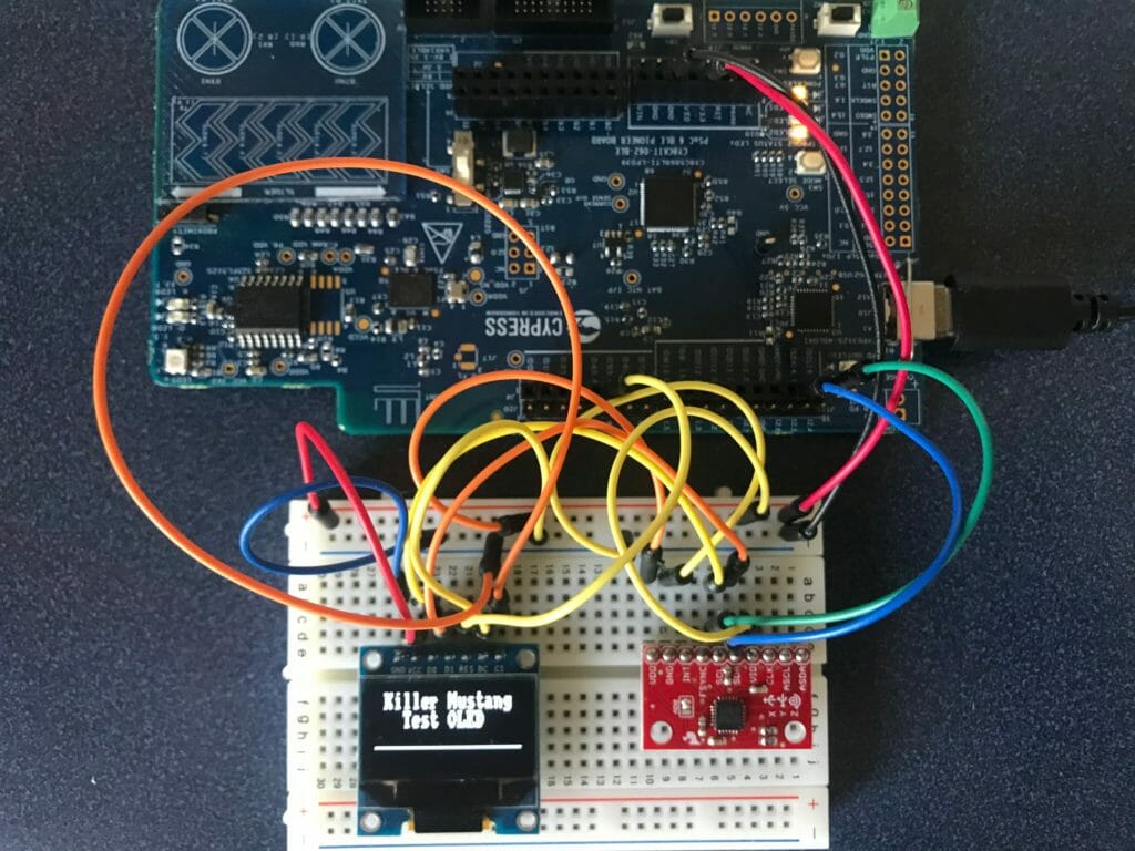
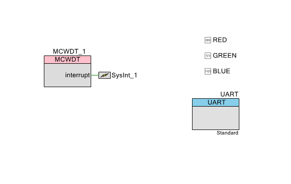
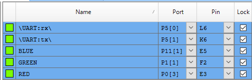
To demonstrate the PSoC 6 Low Power MCWDT, I start by creating a schematic.  It has the three color LEDs pins (RED, GREEN and BLUE), a UART to print out debugging information and finally the MCWDT connected to an interrupt.

PSoC 6 Low Power MCWDT Schematic

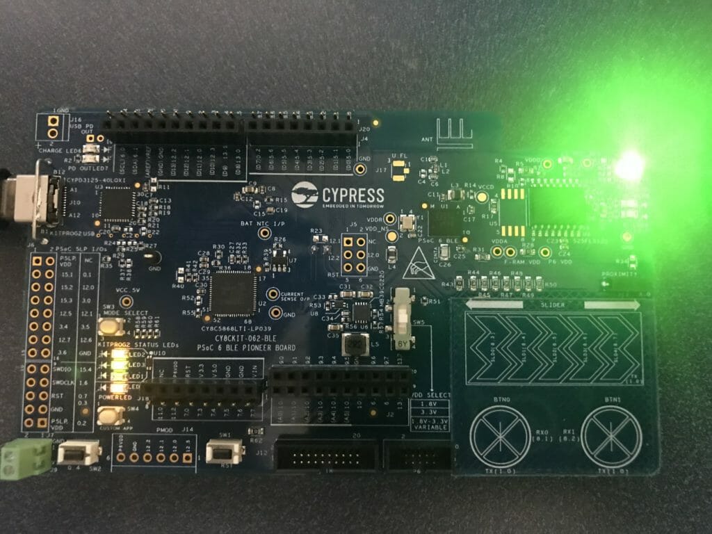
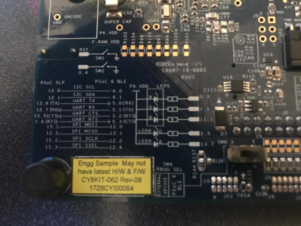
The pin assignment is chosen to match the pins on my CY8CKIT-062-BLE Development kit. (look on the back)

PSoC 6 Pin Configuration

CY8CKIT-062-BLE

Configuring the Interrupts

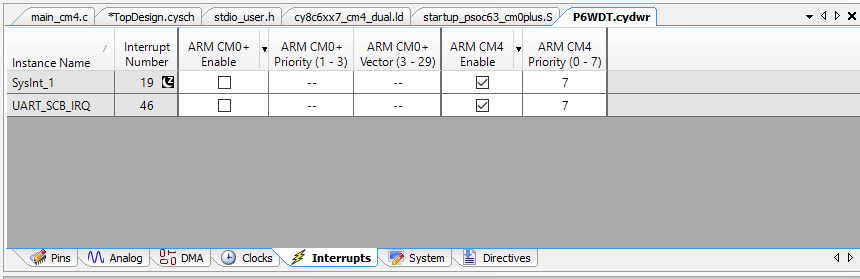
When you place an interrupt component in PSoC Creator (which I did in the above schematic), it will then appear in the DWR on the interrupt page.  Here you can assign the interrupt to either of the MCU Cores, or I suppose both, though I think that is  probably a horrible idea.

PSoC Creators “fitter” sees that the interrupt is connected to a MCWDT.  It then does the job of attaching the interrupt to the correct interrupt number, in this case 19

PSoC 6 Interrupts

All the screen above does is create a little block of code in the firmware file cyfitter_sysint_cfg.c.  Look at the structure called cy_stc_sysint_t SysInt_1_cfg in the automatically generated code:

/*******************************************************************************
* File Name: cyfitter_sysint_cfg.c
* 
* PSoC Creator  4.2 Nightly Build 543
*
* Description:
* 
* This file is automatically generated by PSoC Creator.
*
********************************************************************************
* Copyright (c) 2007-2017 Cypress Semiconductor.  All rights reserved.
* You may use this file only in accordance with the license, terms, conditions, 
* disclaimers, and limitations in the end user license agreement accompanying 
* the software package with which this file was provided.
********************************************************************************/

#include "cyfitter_sysint.h"
#include "cyfitter_sysint_cfg.h"

/* ARM CM4 */
#if (((__CORTEX_M == 4) && (CY_CORE_ID == 0)))

    /* SysInt_1 */
    const cy_stc_sysint_t SysInt_1_cfg = {
        .intrSrc = (IRQn_Type)SysInt_1__INTC_NUMBER,
        .intrPriority = SysInt_1__INTC_CORTEXM4_PRIORITY
    };

    /* UART_SCB_IRQ */
    const cy_stc_sysint_t UART_SCB_IRQ_cfg = {
        .intrSrc = (IRQn_Type)UART_SCB_IRQ__INTC_NUMBER,
        .intrPriority = UART_SCB_IRQ__INTC_CORTEXM4_PRIORITY
    };

#endif /* ((__CORTEX_M == 4) && (CY_CORE_ID == 0)) */

So, where does SysInt_1__INTC_NUMBER get set?  That is done by the fitter in cyfitter_sysint.h.  Here is the automatically generated code:

/*******************************************************************************
* File Name: cyfitter_sysint.h
* 
* PSoC Creator  4.2 Nightly Build 543
*
* Description:
* 
* This file is automatically generated by PSoC Creator.
*
********************************************************************************
* Copyright (c) 2007-2017 Cypress Semiconductor.  All rights reserved.
* You may use this file only in accordance with the license, terms, conditions, 
* disclaimers, and limitations in the end user license agreement accompanying 
* the software package with which this file was provided.
********************************************************************************/

#ifndef INCLUDED_CYFITTER_SYSINT_H
#define INCLUDED_CYFITTER_SYSINT_H
#include "cy_device_headers.h"

/* SysInt_1 */
#define SysInt_1__INTC_CORTEXM4_ASSIGNED 1
#define SysInt_1__INTC_CORTEXM4_PRIORITY 7u
#define SysInt_1__INTC_NUMBER 19u
#define SysInt_1_INTC_CORTEXM4_ASSIGNED 1
#define SysInt_1_INTC_CORTEXM4_PRIORITY 7u
#define SysInt_1_INTC_NUMBER 19u

/* UART_SCB_IRQ */
#define UART_SCB_IRQ__INTC_CORTEXM4_ASSIGNED 1
#define UART_SCB_IRQ__INTC_CORTEXM4_PRIORITY 7u
#define UART_SCB_IRQ__INTC_NUMBER 46u
#define UART_SCB_IRQ_INTC_CORTEXM4_ASSIGNED 1
#define UART_SCB_IRQ_INTC_CORTEXM4_PRIORITY 7u
#define UART_SCB_IRQ_INTC_NUMBER 46u

#endif /* INCLUDED_CYFITTER_SYSINT_H */

To make all of this work, you simply need to install the interrupt handler by calling Cy_SysInt_Init in your main.c.

    // install ISR...
    Cy_SysInt_Init(&SysInt_1_cfg,myWDT);
    NVIC_EnableIRQ(SysInt_1_INTC_NUMBER);

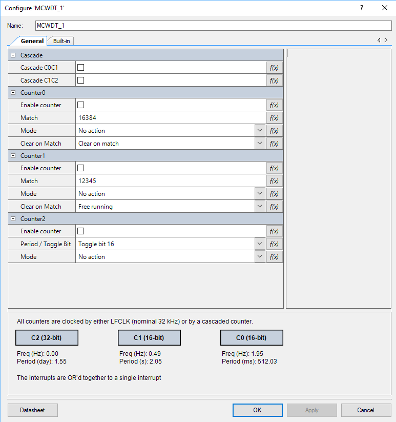
Configuring the PSoC 6 Low Power MCWDT with the GUI

As with all (or almost all) PSoC components, you can configure them in the GUI.  In the picture below you can see that you can set

  1. Enable/Disable
  2. The Match Value
  3. The Mode (interrupt, watchdog, none)
  4. Free Running or Clear on Match
  5. The Cascade (meaning connect the counters together)

PSoC 6 Low Power MCWDT Configuration GUI

All of those configuration items will end up in the file MCWDT_1_PDL.c in a structure that looks like this:

/** The instance-specific configuration structure. This should be used in the 
*  associated MCWDT_1_Init() function.
*/ 
const cy_stc_mcwdt_config_t MCWDT_1_config =
{
    .c0Match     = MCWDT_1_C0_MATCH,
    .c1Match     = MCWDT_1_C1_MATCH,
    .c0Mode      = MCWDT_1_C0_MODE,
    .c1Mode      = MCWDT_1_C1_MODE,
    .c2ToggleBit = MCWDT_1_C2_PERIOD,
    .c2Mode      = MCWDT_1_C2_MODE,
    .c0ClearOnMatch = (bool)MCWDT_1_C0_CLEAR_ON_MATCH,
    .c1ClearOnMatch = (bool)MCWDT_1_C1_CLEAR_ON_MATCH,
    .c0c1Cascade = (bool)MCWDT_1_CASCADE_C0C1,
    .c1c2Cascade = (bool)MCWDT_1_CASCADE_C1C2
};

Then you can either call the MCWDT_1_Start() function or you can call the PDL function Cy_MCWDT_Init(&MCWDT_1_config);

PSoC 6 Low Power MCWDT Firmware

You can also configure the PSoC 6 Low Power MCWDT in your firmware as I have done below:

   Cy_MCWDT_Unlock(MCWDT_STRUCT0);
    // Turn off all of the counters
    Cy_MCWDT_Disable(MCWDT_STRUCT0,CY_MCWDT_CTR0 | CY_MCWDT_CTR1 | CY_MCWDT_CTR2,100);
    Cy_MCWDT_ResetCounters(MCWDT_STRUCT0,CY_MCWDT_CTR0,100);
    Cy_MCWDT_ResetCounters(MCWDT_STRUCT0,CY_MCWDT_CTR1,100);
    
    Cy_MCWDT_SetMode(MCWDT_STRUCT0,0,CY_MCWDT_MODE_NONE); // 0=Counter 0
    Cy_MCWDT_SetMode(MCWDT_STRUCT0,1,CY_MCWDT_MODE_INT);  // 1=Counter 1
    
    Cy_MCWDT_SetCascade(MCWDT_STRUCT0,CY_MCWDT_CASCADE_C0C1 );
    
    Cy_MCWDT_SetInterruptMask(MCWDT_STRUCT0,CY_MCWDT_CTR1); // Only take ints from counter 1
    
    // delay = 32768*16 = 8 seconds & 32khz
    Cy_MCWDT_SetMatch(MCWDT_STRUCT0,0,32768,100);
    Cy_MCWDT_SetMatch(MCWDT_STRUCT0,1,16,100);
       
    Cy_MCWDT_SetClearOnMatch(MCWDT_STRUCT0,0,1);
    Cy_MCWDT_SetClearOnMatch(MCWDT_STRUCT0,1,1);
    
    Cy_MCWDT_Enable(MCWDT_STRUCT0,CY_MCWDT_CTR0|CY_MCWDT_CTR1,100);

The Interrupt Service Routine (ISR) for the MCWDT is pretty simple.  It just reads the cause of the interrupt, which could be any one of the counters in the MCWDT (or more than one of them).  Then it inverts either the Red, Green or Blue LED.  And finally it clears the interrupt source inside of the MCWDT.

void myWDT(void)
{
    uint32_t cause;
    cause = Cy_MCWDT_GetInterruptStatusMasked(MCWDT_STRUCT0);
    if(cause & CY_MCWDT_CTR0)
    {
        Cy_GPIO_Inv(RED_PORT,RED_NUM);
    }
    
    if(cause & CY_MCWDT_CTR1)
    {
        Cy_GPIO_Inv(GREEN_PORT,GREEN_NUM);
    }
    
    if(cause & CY_MCWDT_CTR2)
    {
        Cy_GPIO_Inv(BLUE_PORT,BLUE_NUM);
    }
    
    Cy_MCWDT_ClearInterrupt(MCWDT_STRUCT0,cause);
}

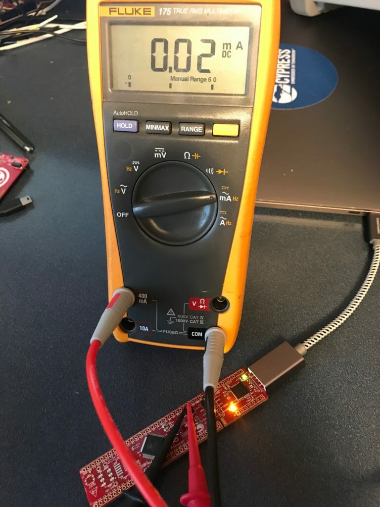
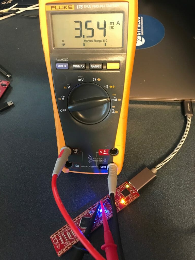
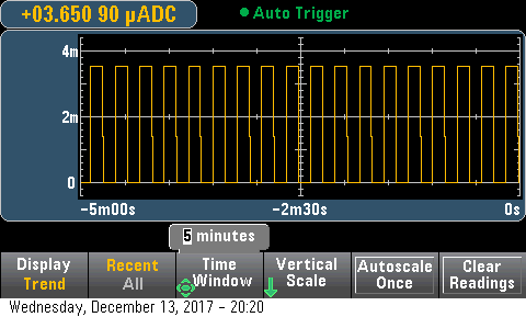
When I run this program I get a slowly blinking Green LED in Low Power mode:

PSoC 6 Low Power MCWDT

PSoC 4200M Low Power with WDTs

Summary

The last few weeks of my technical life have been frustrating.  Nothing and I mean nothing has been easy.  A few weeks ago I replied to a comment about cascading the watch dog timers in the PSoC 4200M to extend the sleep time – the article was called “PSoC 4200M WDT Long Deep Sleep“.  I wanted to measure power to see what exactly was happening.  But the great technical gods were conspiring against me and I had tons of problems.  Well I have things sorted out.  In this article I will build a project using the PSoC 4200M Watch Dog Timers and show the power measurements on the CY8CKIT-043 and CY8CKIT-044.  I will include PSoC 4200M low power measurements at 5V and 3.3V as well as with both the ILO and the WCO as the source of the WDT.  To do this I:

  1. Created a PSoC 4200M low power project
  2. Modified the CY8CKIT-043M
  3. Reject the Fluke 175
  4. Read the Keysite 34465A Multimeter Manual
  5. PSoC 4200M Low Power Current Measurement

PSoC 4 Low Power Firmware

First I create a schematic.  This includes 4 digital output pins.  The GREEN, RED and BLUE are attached to the tri-color LED.  A UART to print the status of the startup.  And an interrupt connected to the WDT Interrupt.

PSoC 4200M Low Power Schematic

The next thing to do is to make sure that the WDT is being driven by the ILO.  I also turn off the three WDTs because I will configure them in the firmware.

PSoC 4200M Low Power Clock Configuration

In order to get low power you need to switch the debugging pins off i.e. make them GPIOs.  You can do this on the DWR System Screen.

Finally write some firmware.  The firmware simply

  1. Blinks the LED 10 times
  2. Prints “Started” to the UART, waits until the buffer is flushed, then turns off the UART to make sure the power is low.
  3. Configure the Watch Dog Timers.  This could have been done on the Low Frequency Clock Screen (except for the cascading of timers which had to be done with firmware)
  4. Turn off the Pin, Deep Sleep the chip… and wait.  When an interrupt from the WDT occurs, it calls the ISR (next section)
int main(void)
{
    trigger_Write(1); // Measure Startup

    // Blink the LED when the PSoC Starts
    for(int i=0;i<10;i++)
    {
        BLUE_Write(~BLUE_Read());
        CyDelay(200);
    }
    BLUE_Write(0);
    
    UART_Start();
    UART_UartPutString("Started\n");
    isr_1_StartEx(wdtInterruptHandler);

    while(UART_SpiUartGetTxBufferSize()); // Wait until the UART has flushed - then turn off the power
    UART_Stop();

    CySysWdtUnlock(); // Enable modification of the WDT Timers
    
    // Turn off the WDTs (all three of them)
    CySysWdtDisable(CY_SYS_WDT_COUNTER0_MASK); 
    CySysWdtDisable(CY_SYS_WDT_COUNTER1_MASK);
    CySysWdtDisable(CY_SYS_WDT_COUNTER2_MASK);
    
    // Make Timer 0 & 1 run with no interrupt, and 2 cause an interrupt
    CySysWdtSetMode(CY_SYS_WDT_COUNTER0,CY_SYS_WDT_MODE_NONE);
    CySysWdtSetMode(CY_SYS_WDT_COUNTER1,CY_SYS_WDT_MODE_NONE);
    CySysWdtSetMode(CY_SYS_WDT_COUNTER2,CY_SYS_WDT_MODE_INT);
    
    // Set the time to 32768/(64*64*2^6) = 32768/(2^18) = 0.125 = 1/8 Hz
    CySysWdtSetMatch(CY_SYS_WDT_COUNTER0, 64);
    CySysWdtSetMatch(CY_SYS_WDT_COUNTER1, 64);
    CySysWdtSetToggleBit(6);
    
    CySysWdtSetClearOnMatch(CY_SYS_WDT_COUNTER0,1); // When counter his period reset counter
    CySysWdtSetClearOnMatch(CY_SYS_WDT_COUNTER1,1);

    CySysWdtSetCascade(CY_SYS_WDT_CASCADE_01 | CY_SYS_WDT_CASCADE_12); // Cascade 0-1-2
    CySysWdtEnable(CY_SYS_WDT_COUNTER0_MASK | CY_SYS_WDT_COUNTER1_MASK | CY_SYS_WDT_COUNTER2_MASK );
    
    trigger_Write(0); // End measurement

    CyGlobalIntEnable; /* Enable global interrupts. */
    
    for(;;)
    {
        trigger_Write(0); // setup trigger
        CySysPmDeepSleep(); // wait for interrupt in deep sleep
    }
}

The ISR first turns on the trigger pin (which I will use in the next article to trigger the oscilloscope).  Then it determines which timer caused the interrupt.  Originally I was blinking different color LEDs when I was trying to figure out what was happening.  With the current configuration WDT0 and WDT1 will never trigger an interrupt.  Finally it clears the interrupt and returns.  When it returns the main loop will turn off the trigger pin and then deep sleep.

void wdtInterruptHandler()
{
    trigger_Write(1); // Chip is woken up 
    uint32 reason = CySysWdtGetInterruptSource();
    
    if(reason & CY_SYS_WDT_COUNTER0_INT)
        RED_Write(~RED_Read());
  
    if(reason & CY_SYS_WDT_COUNTER1_INT)
        GREEN_Write(~GREEN_Read());
  
    if(reason & CY_SYS_WDT_COUNTER2_INT)
        BLUE_Write(~BLUE_Read());
  
    CySysWdtClearInterrupt(reason);  // Clear the WDT Interrupt
}

Modified the CY8CKIT-043

In order to measure current with the. CY8CKIT-043 you need to remove the 0 ohm resistor R22 and install a jumper (J4) so that you can measure the current into the board.

CY8CKIT-043 Schematic

R22 is on the back of the development kit.  You can see that I circled it.

CY8CKIT-042 modification for PSoC 4200M Low Power Measurement

Then install a jumper into J4. I  just use a two pin break away header.

CY8CKIT-042 modification for PSoC 4200M Low Power Measurement

Fluke 175

According to the AN 86233 PSoC® 4 and PSoC Analog Coprocessor Low-Power Modes and Power Reduction Techniques I should be able to get 1.3uA in deep sleep 1.3mA in active.

PSoC 4200M Low Power Specs

I started with my trusty Fluke 175… but quickly realized that uA are not in the cards.  It appears that the lowest it can measure is 10’s of microamps.

PSoC 4200M Low Power Measurement with Fluke

It does fine with the active mode.

PSoC 4200M Low Power Measurement with Fluke

Keysight 34465A 6 1/2 Digit Multimeter

The good news is that I also have a Keysight 34465A 6/12 digit multimeter.  In the 1uA range it can measure +- 0.055% of 1uA or about 5nA (is that right?)

Keysight 34655A Specs

Keysight 34665A Current Measurement Ranges

It also doesnt change the input power supply very much.  In fact only 0.0011v in 3.3v is negligible.

Keysight 34465A Drop Out Voltage

PSoC 4200M Low Power Current Measurement

I wanted to measure Active, Sleep, Deep Sleep on the CY8CKIT-043 and CY8CKIT-44 with the WCO on and off.  In the two pictures below you can see that the system is taking between 3.6uA and 4.2uA in Deep Sleep.

PSoC 4200M Low Power Measurement

PSoC 4200M Low Power Measurement

Here are tables with all of the measurements.

5V – CY8CKIT-044

Mode WCO On WCO Off
Active 12..860mA 12.859mA
Sleep 5.339mA 5.335mA
Deep Sleep 4.206uA 1.078uA

3.3V – CY8CKIT-044

Mode WCO On WCO Off
Active 12.84mA 12.84mA
Sleep 5.328mA 5.327mA
Deep Sleep 4.096uA 0.940uA

5V – CY8CKIT-043

Mode WCO Off
Active 12.711mA
Sleep 5.352mA
Deep Sleep 3.632uA

The other thing that is pretty cool with the KeySite is that you can put it into “Trend” mode and it can display the current readings over a long period.  In the picture below I am flashing the LED which takes around 3.5mA @ 3.3v on this development kit.

PSoC 6, FreeRTOS & SSD1306 OLED Display

Summary

This week I have been working with my friend Hassane El Khoury on his hobby project which has the SSD1306 in it. [if you want to know more about the project, leave a comment and maybe he will answer the question].  I have been helping him get a number of things going including this display which I have written about before.  This article describes the integration of the SSD1306 OLED Display into his project with the PSoC 6 & FreeRTOS.

Firmware Architecture

Hassane started his career as an Automotive System Designer, then he worked as an Applications Engineer, so he has “mad” skills in this area.  He is building his project with a PSoC 6 and is heavily using FreeRTOS (which is new for him).  He has been distracted with some other thing the last few years, so I have been serving as a consultant on the latest PSoC stuff to smooth the learning curve.  In this case PSoC6, FreeRTOS and the SSD1306 OLED Display.  I have only used the SSD1306 OLED Display with PSoC 4 and WICED, but I ASSUMED (incorrectly assumed… which I will talk about in the next article) that there would be no problems making it work in that environment.

Hassane is all about reuse and he had copied the design of this section of his project from my article on using queues with FreeRTOS.  It looks like this.

  1. There is a task that manages the I2C and talks directly to the SCB hardware and the I2C devices
  2. There is a task that manages the OLED

ssd1306 oled display architecture

Originally the OLED task was talking directly to the I2C via the SCB (the red line on the picture).  Remember from the article on the U8G2 library, the hardware abstraction layer looks like this.  Basically it

  1. Sends an I2C Start at the start of the U8G2 transaction
  2. Sends an I2C Stop at the end of the tranaction
  3. Send the number of bytes called for.
uint8_t u8x8_I2C_HW(u8x8_t *u8x8, uint8_t msg, uint8_t arg_int, void *arg_ptr)
{
    uint8_t *data;
    switch(msg)
    {
        case U8X8_MSG_BYTE_SEND:            
            data = (uint8_t *)arg_ptr;
            while( arg_int > 0 )
            {
                Cy_SCB_I2C_MasterWriteByte(I2Cm1_HW, *data, I2C_TIMEOUT, &I2Cm1_context);
  	            data++;
	            arg_int--;
            }
        break;
      
        case U8X8_MSG_BYTE_START_TRANSFER:
            Cy_SCB_I2C_MasterSendStart(I2Cm1_HW, u8x8_GetI2CAddress(u8x8)>>1, CY_SCB_I2C_WRITE_XFER, I2C_TIMEOUT, &I2Cm1_context);
         break;
        
        case U8X8_MSG_BYTE_END_TRANSFER:
            Cy_SCB_I2C_MasterSendStop(I2Cm1_HW, I2C_TIMEOUT, &I2Cm1_context);
        break;
    
        default:
            return 0;
    }
    
    return 1;
}

The problem with this design is that it takes over the I2C hardware and requires exclusive control.  Moreover, it leaves you program hung while the transaction is happening.  To solve this problem, there are three options

  1. “Assign” the SCB block to the exclusive use of this task (makes it hard to share with other I2C devices)
  2. Create a mutex for the SCB.  This will work, but it will not allow the task to “queue” transactions and move on
  3. Create a task to manage the SCB with a queue (the option that Hassane chose)

The I2C message queue holds complete transactions.  Each transaction (which he called I2Cm_transaction_t) looks like this:

typedef enum I2Cm_transactionMethod {
    I2CM_READ,
    I2CM_WRITE
} I2Cm_transactionMethod_t;

typedef enum I2Cm_registerAddresType {
    I2CM_NONE, 
    I2CM_BIT8,
    I2CM_BIT16
} i2cm_registerAddressType_t;

typedef struct I2Cm_transaction {
    I2Cm_transactionMethod_t I2Cm_method;        // I2CM_READ or I2CM_WRITE
    uint8_t I2Cm_address;                        // The I2C Address of the slave
    i2cm_registerAddressType_t I2Cm_regType;     // I2CM_8BIT or I2CM_16BIT
    uint16_t I2Cm_register;                      // The register in the slave    
    uint8_t *I2Cm_bytes;                         // A pointer to the data to be written (or a place to save the data)
    uint32_t *I2Cm_bytesProcessed;               // A return value with the number of bytes written
    uint32_t I2Cm_byteNum;                       // How many bytes are in the request
    SemaphoreHandle_t I2Cm_doneSemaphore;        // If you want a semaphore flagging that the transaction is done 
} I2Cm_transaction_t;

In order to fix the the HAL you just sets up a transaction at the start of the task:

   memset(&OLEDtransaction,0,sizeof(OLEDtransaction));
	OLEDtransaction.I2Cm_method = I2CM_WRITE;
	OLEDtransaction.I2Cm_address = OLED_ADDRESS_1;
	OLEDtransaction.I2Cm_regType = I2CM_NONE;
	OLEDtransaction.I2Cm_bytes = buff;
	OLEDtransaction.I2Cm_bytesProcessed = &numProcessed;	
    OLEDtransaction.I2Cm_doneSemaphore = xSemaphoreCreateBinary();

Then queue up the bytes into a buffer, and flush the buffer when the “U8X8_MSG_BYTE_END_TRANSFER” message comes

uint8_t u8x8_I2C_HW(u8x8_t *u8x8, uint8_t msg, uint8_t arg_int, void *arg_ptr)
{
    uint8_t *data;
    switch(msg)
    {
        case U8X8_MSG_BYTE_SEND:        
            data = (uint8_t *)arg_ptr;
            while( arg_int > 0 )
            {
                buff[buffCount] = *data;
                buffCount += 1;
                CY_ASSERT(buffCount < BUFFSIZE);              
  	            data++;
	            arg_int--;
            }
        break;
 
        case U8X8_MSG_BYTE_START_TRANSFER:
            buffCount = 0;
         break;
        
        case U8X8_MSG_BYTE_END_TRANSFER:
	        OLEDtransaction.I2Cm_byteNum = buffCount;
            I2Cm1RunTransaction(&OLEDtransaction);
        break;
    
        default:
        return 0;
    }
    
    return 1;
}

SSD1306 OLED Display

Now, the short block of test code works perfect:

    u8x8_Setup(&MyI2Cu8x8, u8x8_d_ssd1306_128x32_univision, u8x8_cad_ssd13xx_i2c, u8x8_I2C_HW, u8x8_gpio_and_delay_PSoC6);
        
    u8x8_InitDisplay(&MyI2Cu8x8);  
    u8x8_SetPowerSave(&MyI2Cu8x8,0);
    u8x8_ClearDisplay(&MyI2Cu8x8);
    u8x8_SetFont(&MyI2Cu8x8,u8x8_font_amstrad_cpc_extended_f);
    u8x8_DrawString(&MyI2Cu8x8,0,0," Killer Mustang ");
    u8x8_DrawString(&MyI2Cu8x8,0,1,"   Test OLED    ");
    u8x8_DrawString(&MyI2Cu8x8,0,2,"________________");

And I get a nice output (I wonder what a “Killer Mustang” is?)

In the next article Ill talk about the SS1306 and a problem that I created for myself.