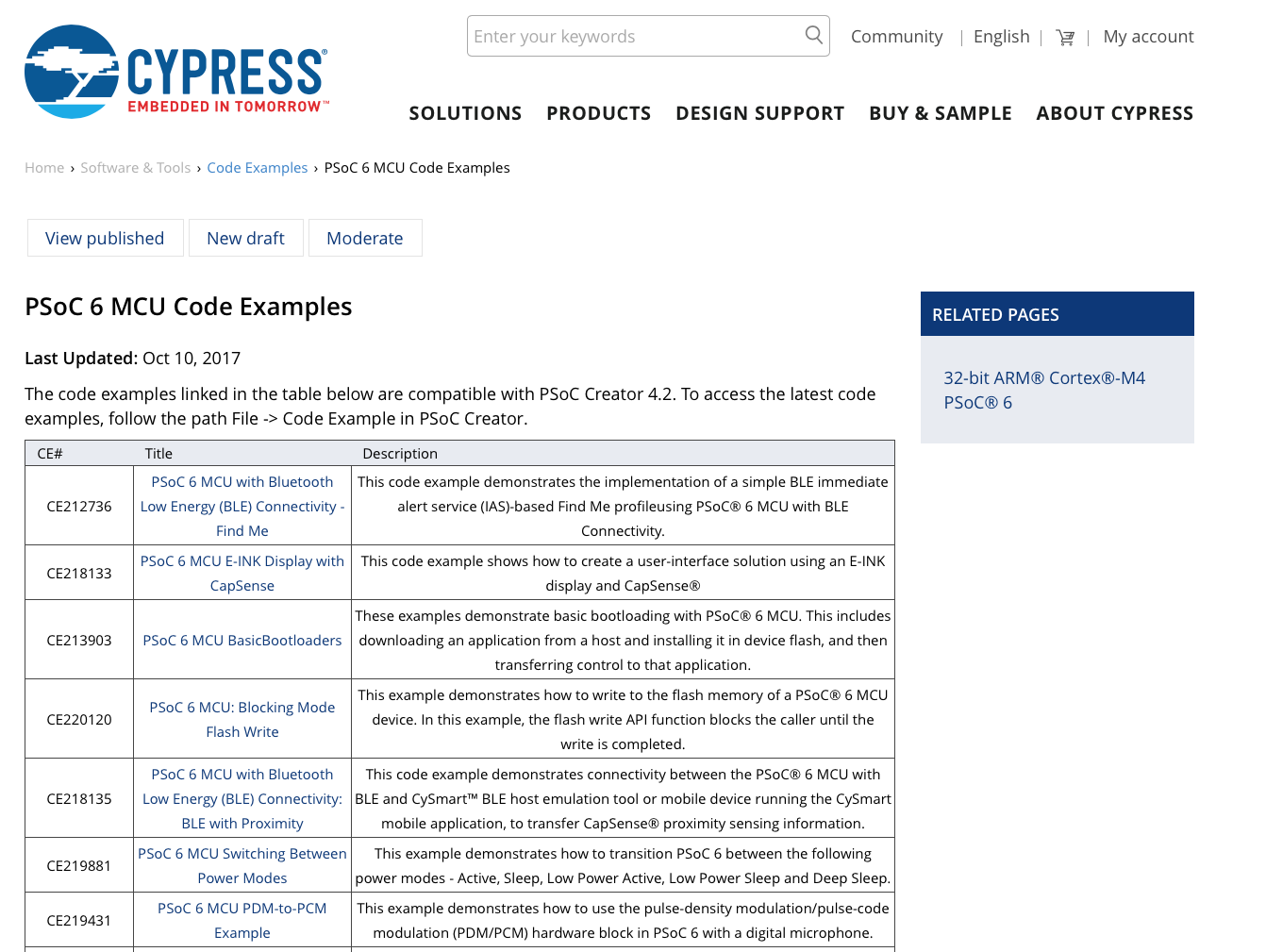
PSoC 6 Introduction
| # |
Title |
Comment |
|---|
| 0 |
A Two Hour PSoC 6 Class |
An introduction to the PSoC 6 class with links to all of the documents |
| 1 |
Resources |
Links to all of the Cypress PSoC 6 information including videos, application notes etc. |
| 2 |
Your First Project |
Learn how to build a PSoC 6 project and program your CY8CKIT-062-BLE development kit |
| 3 |
FreeRTOS and a Debugging UART |
Build a project using FreeRTOS including a debug console with the UART |
| 4 |
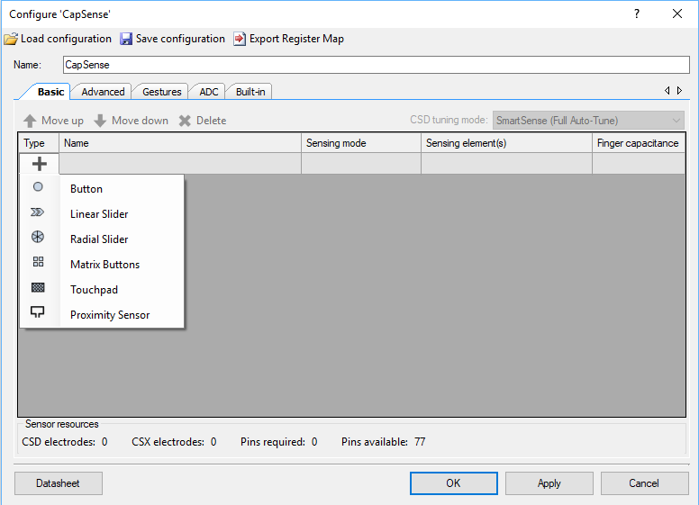
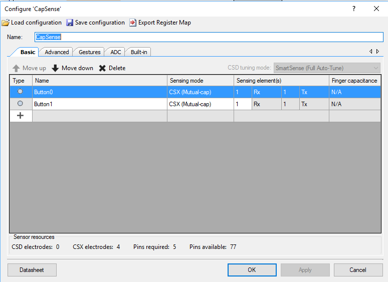
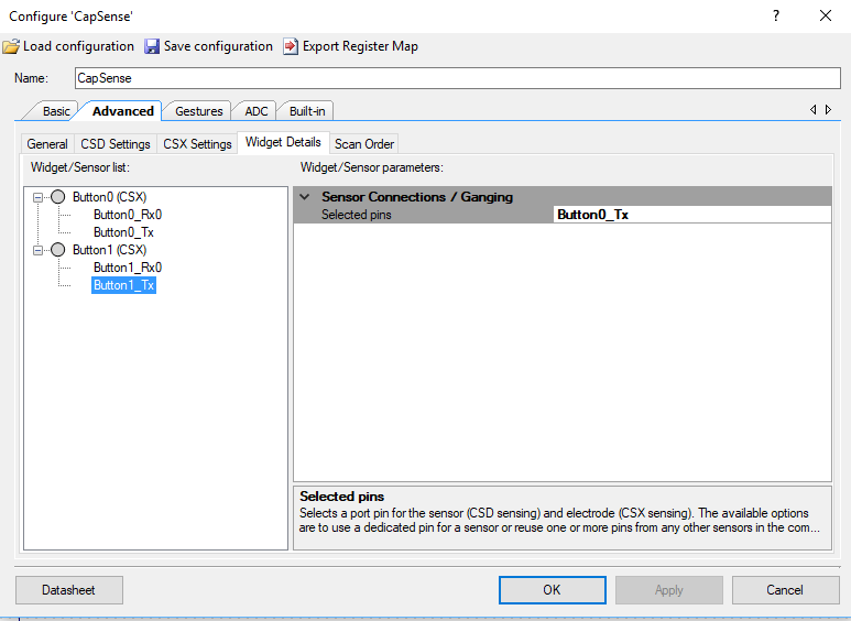
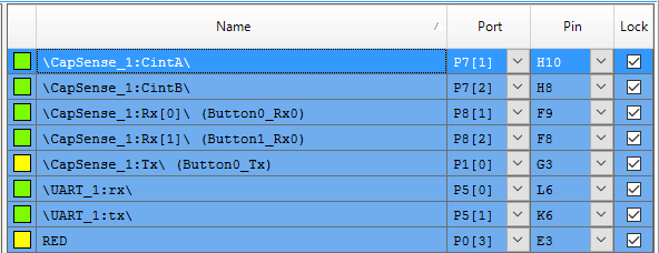
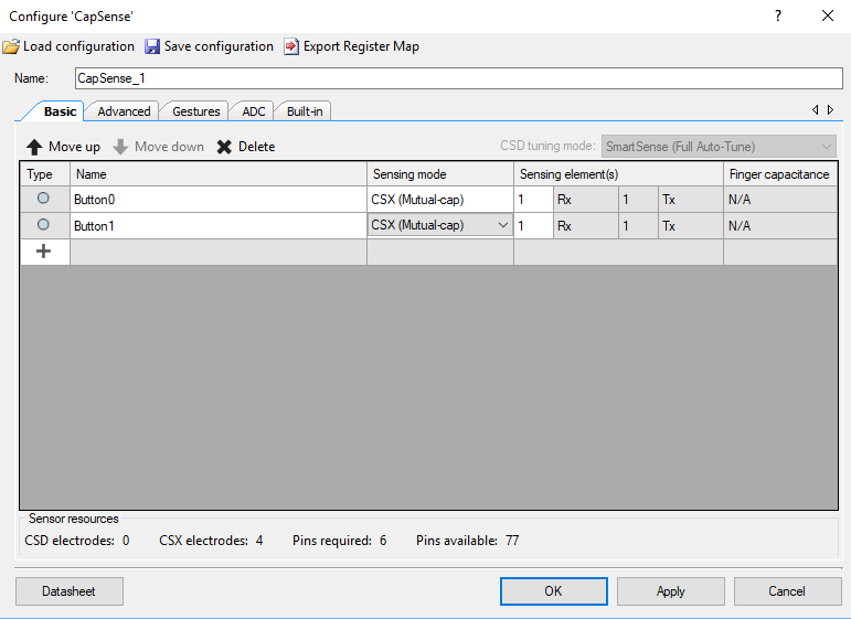
CapSense |
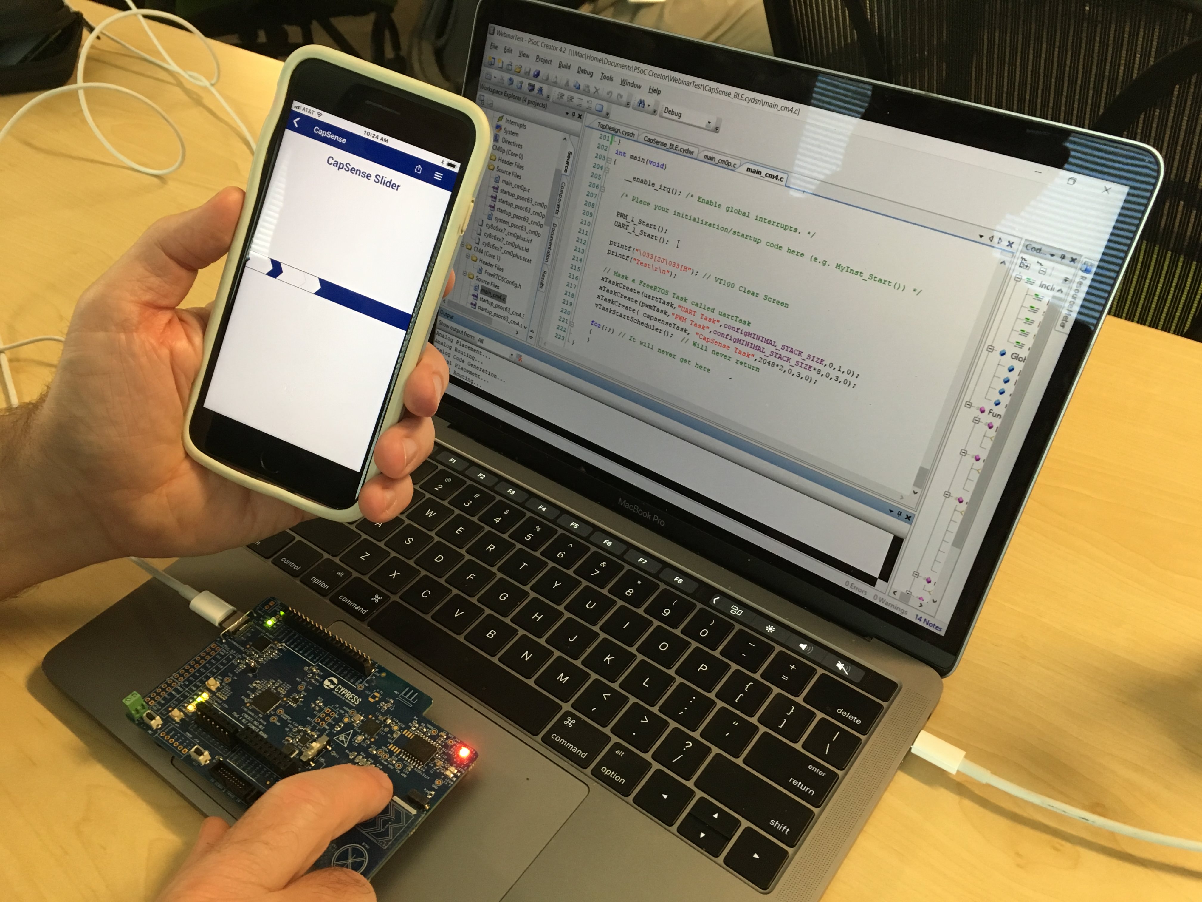
Build a project using the Mutual Cap Buttons and Self Cap Slider |
| 5 |
Bluetooth Low Energy |
Build a CapSense project using BLE and CySmart |
Since I did the webinar several things have happened
- Lesson 4: I fixed an error in the stack size for FreeRTOS
- Lesson 5: The PSoC Creator BLE PDL has been upgraded to greatly simplify the notifyCapSense function
All of the projects are available at git@github.com:iotexpert/psoc-6-introduction.git or www.github.com/iotexpert/psoc-6-introduction
Project Description
This project will show you how to build a PSoC 6 project that is running FreeRTOS and printing information to the debugging UART
How does it work?
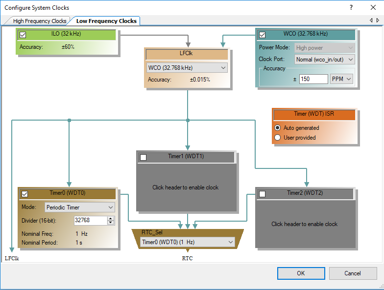
The PSoC 6 is a very capable, fast dual Coretex-M MCU. In order to manage your design complexity that can be attacked with this chip, we gave you the ability to use a Real Time Operating System – FreeRTOS. With a few simple clicks it will startup for you.
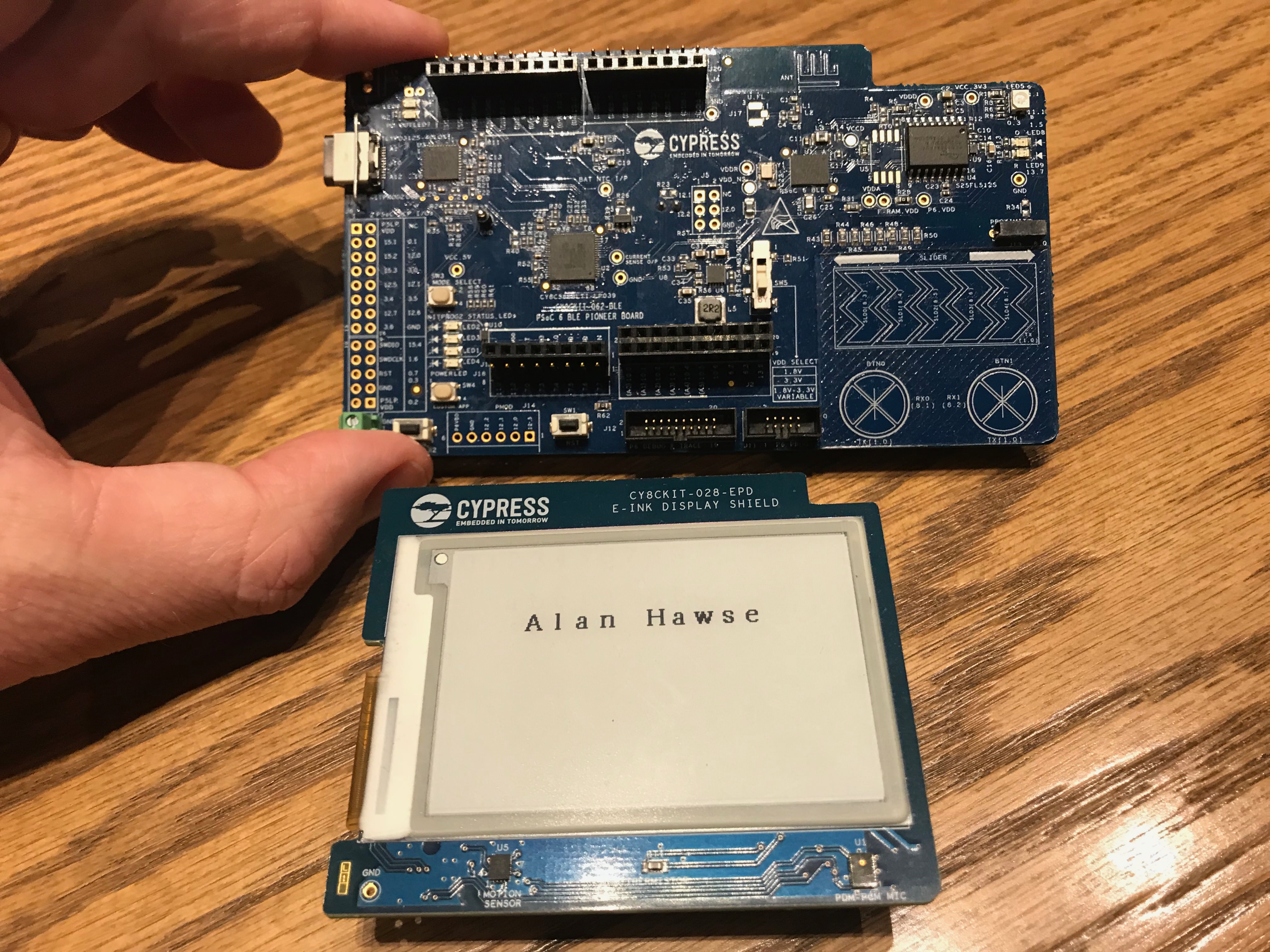
The CY8CKIT-062-BLE has a KitProg-2 Debugger/Programmer on board. In addition to Program/Debug it can also serve as a USB <–> UART bridge which will allow you to open a terminal program on your PC to do Input/Output with a UART in the PSoC 6.
How am I going to do it?
- Copy “MyFirstDesign” to Start a New Project
- Modify the Build Settings to add Debug Printing and FreeRTOS
- Add the UART to the Schematic and Assign the Pins
- Create the UART Test Firmware
- Program and Test the Debug UART
- Modify firmware for FreeRTOS
- Program and Test
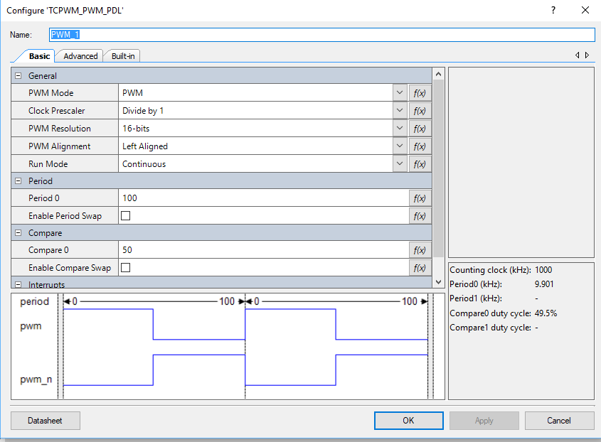
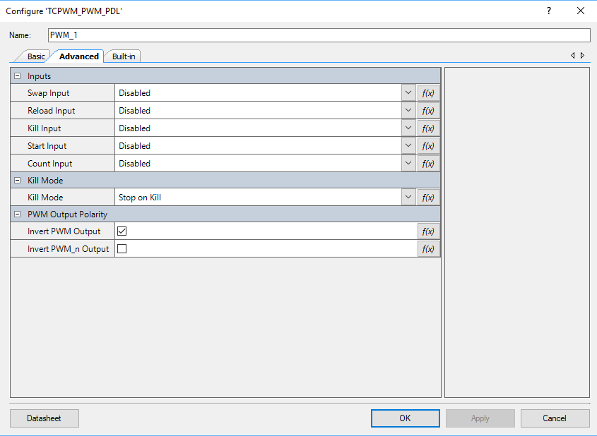
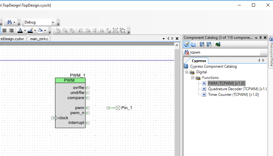
- A Tour of PDL for the TCPWM
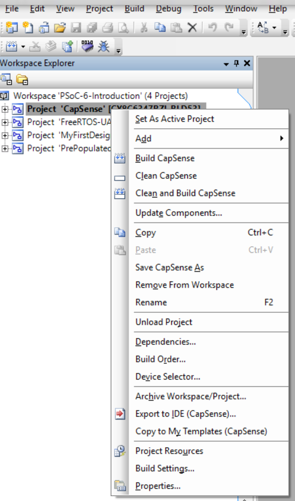
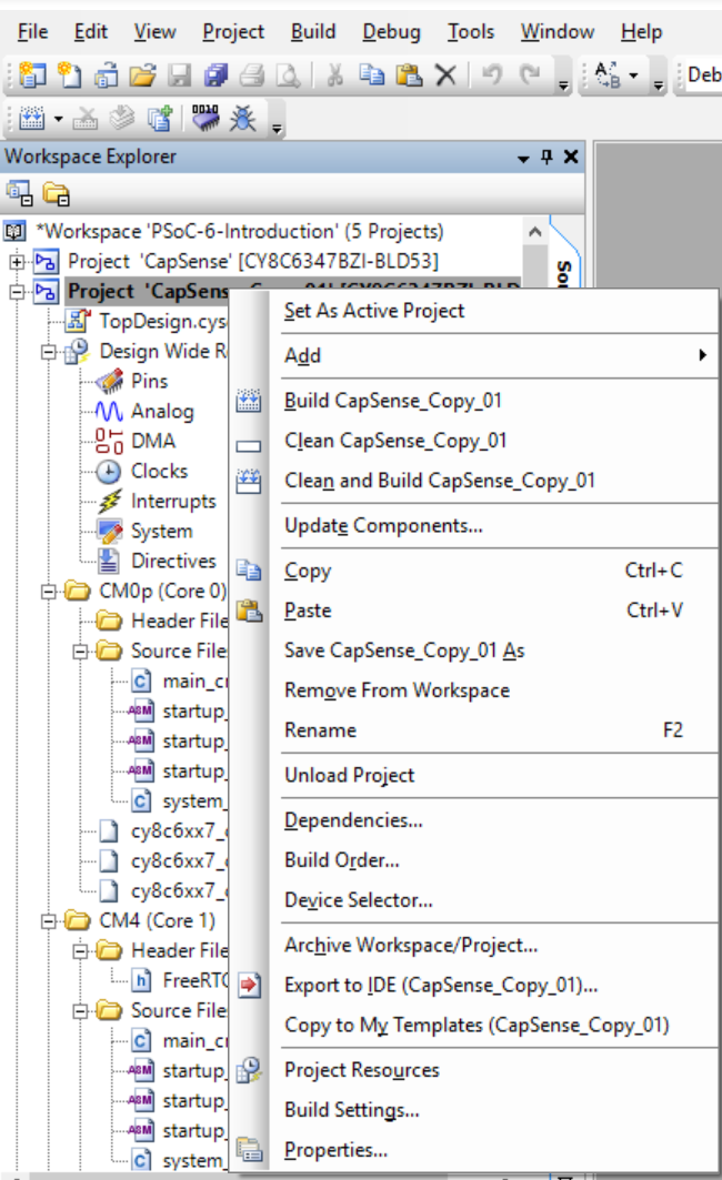
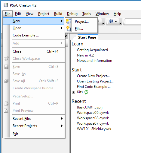
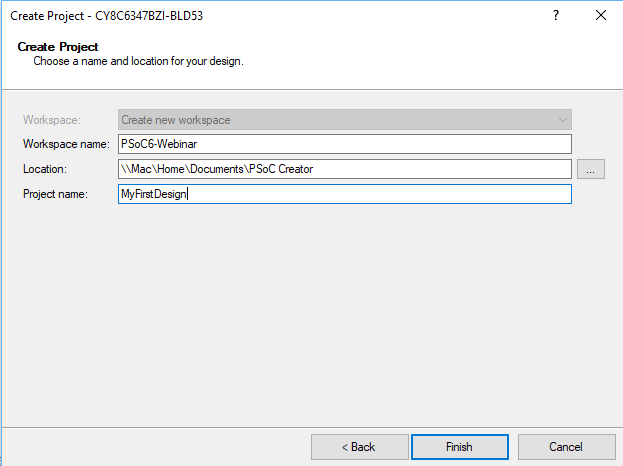
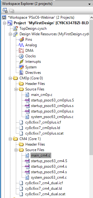
Copy “MyFirstDesign” to Start a New Project
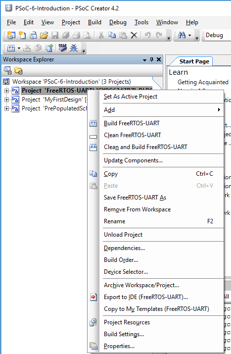
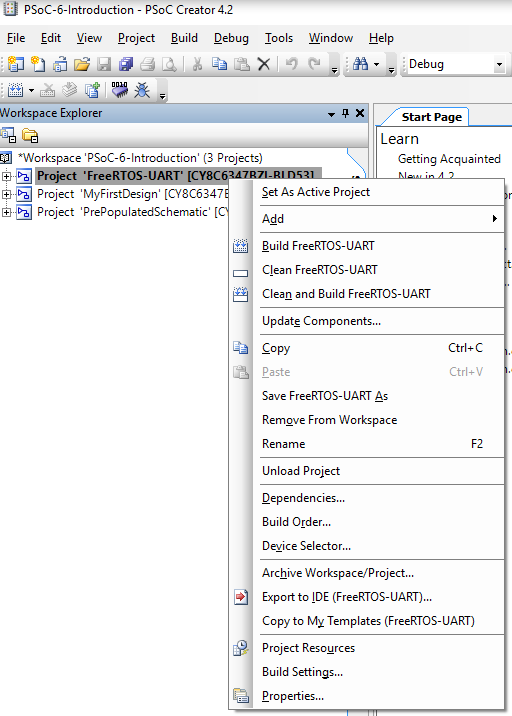
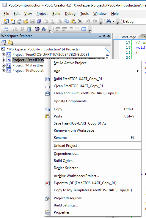
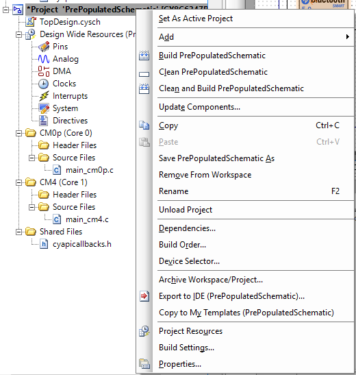
Right click on “MyFirstDesign” and select “Copy”
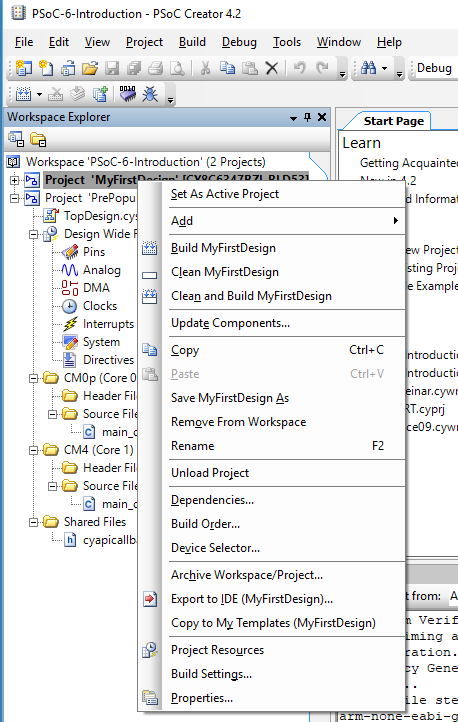
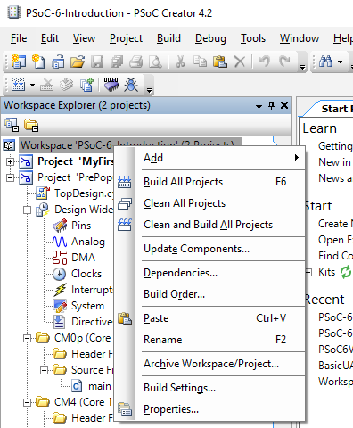
Then right click on the workspace and select “Paste”
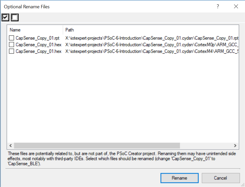
Then right click on “MyFirstDesign_Copy_01” and select rename. Then type in a reasonable name like “FreeRTOS-UART”
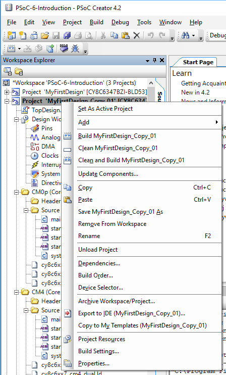
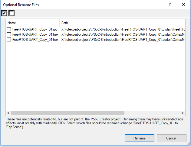
PSoC Creator will ask you about some files. Just click “Rename”

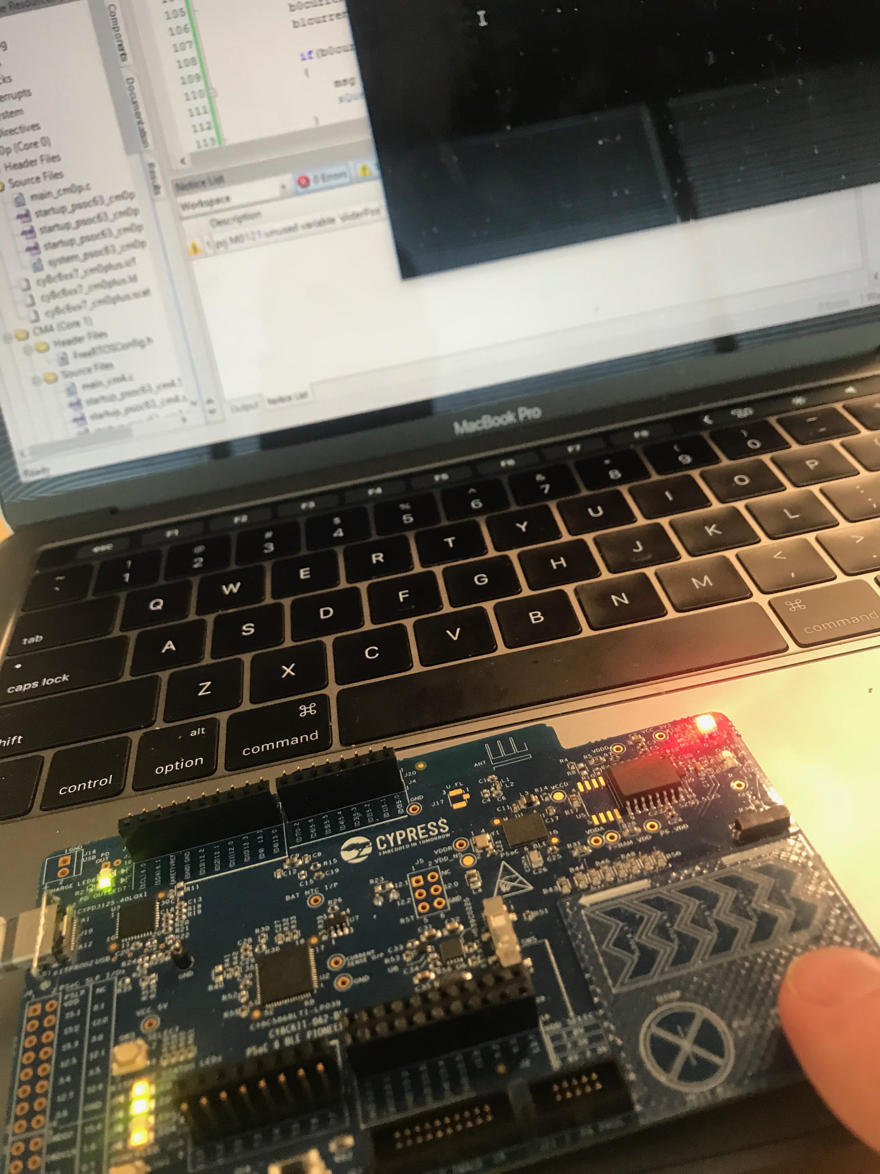
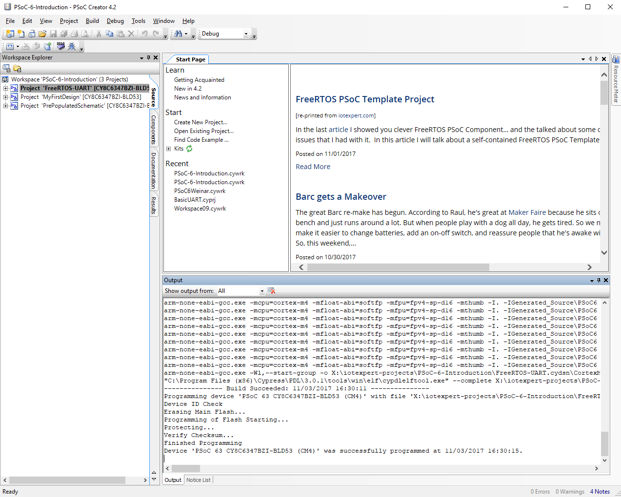
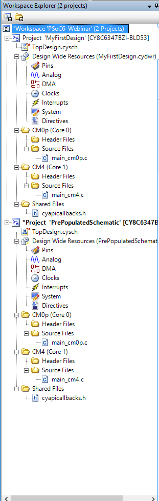
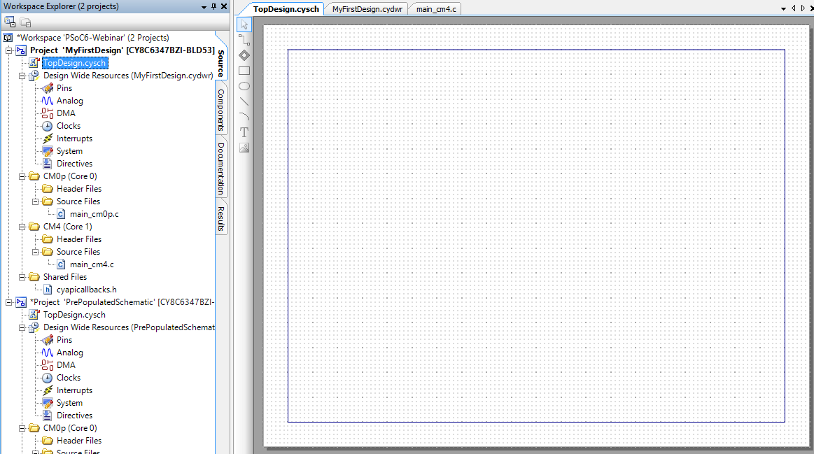
Now you will have three projects in your workspace. I typically click “Program” which will build the copied project and program the development kit… just to make sure that stuff still works.
Modify the build settings to add debug printing and FreeRTOS
You can build massively complex systems with PSoC 6. In order to help manage that complexity I like to turn on debug printing so that “printf” works. I also like to use a Real Time Operating System (FreeRTOS). PSoC Creator has both of these things built in. We called the printf functionality “Retarget I/O” because you need to “target” the Input / Output of the printf … aka STDIN and STDOUT to a peripheral in the PSoC. The best peripheral to use for printf is the UART that is attached to your computer via kitprog2.
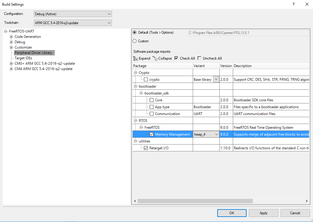
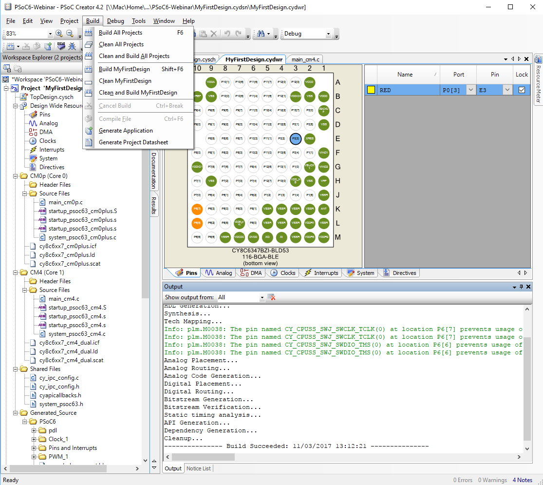
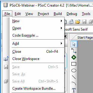
To add printf and FreeRTOS to your project you need to: Right click on the project and select “Build Settings…”
Click on the Peripheral Driver Library and then select “FreeRTOS” and “Memory Management heap_4”. Then select “Retarget I/O”. When you build your project this will cause PSoC Creator to add both of these to your project.

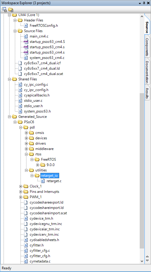
Select Build->Generate Application and notice that PSoC Creator added a number of files to your project including the FreeRTOS, stdio_user.c/.h and retarget_io
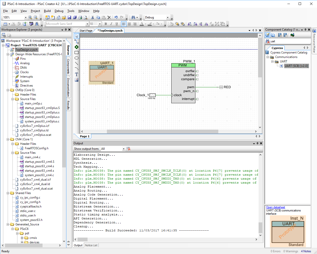
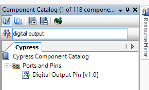
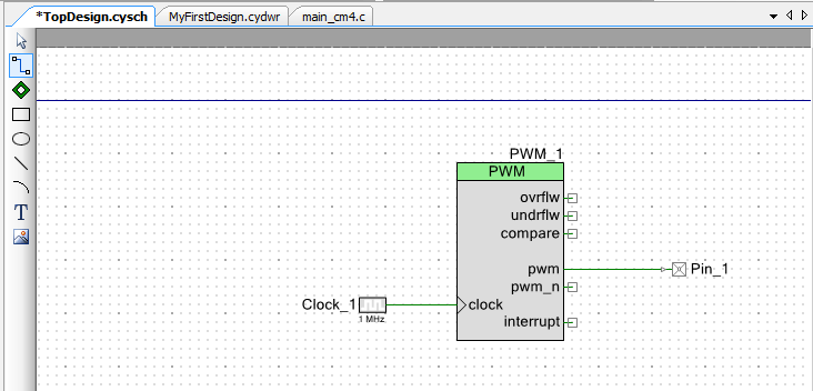
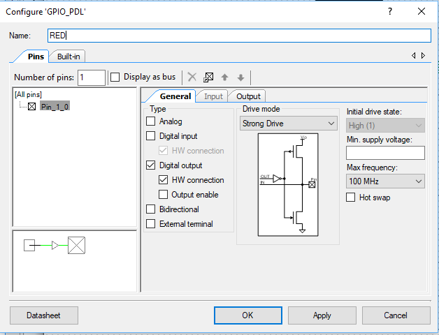
Add the UART to the Schematic and Assign the Pins
In order to printf, getchar and putchar you need to attach c standard library stdin and stdout to “something”. The best “something” is the UART that is attached to the KitProg2 which is attached to your computer. Then you can open a terminal program (like Putty) and read and write to the PSoC.
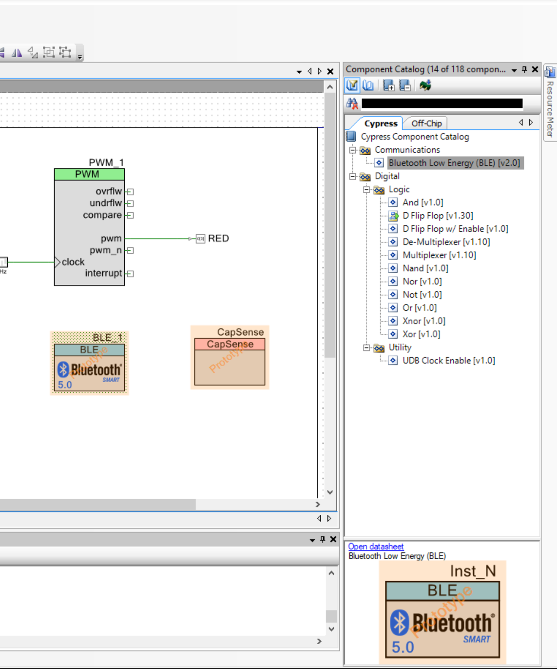
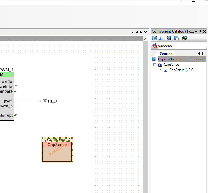
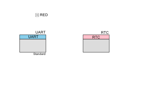
So, to do this you need to add a UART to your design schematic from the component catalog. In the picture below I just typed “uart” in the search box.

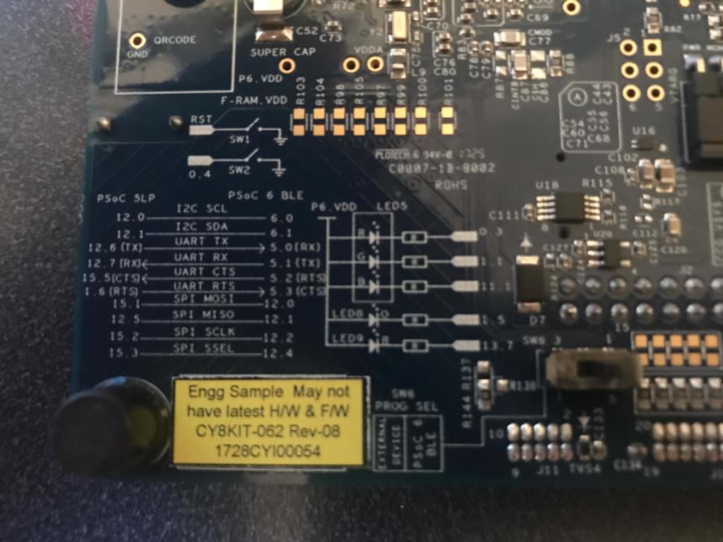
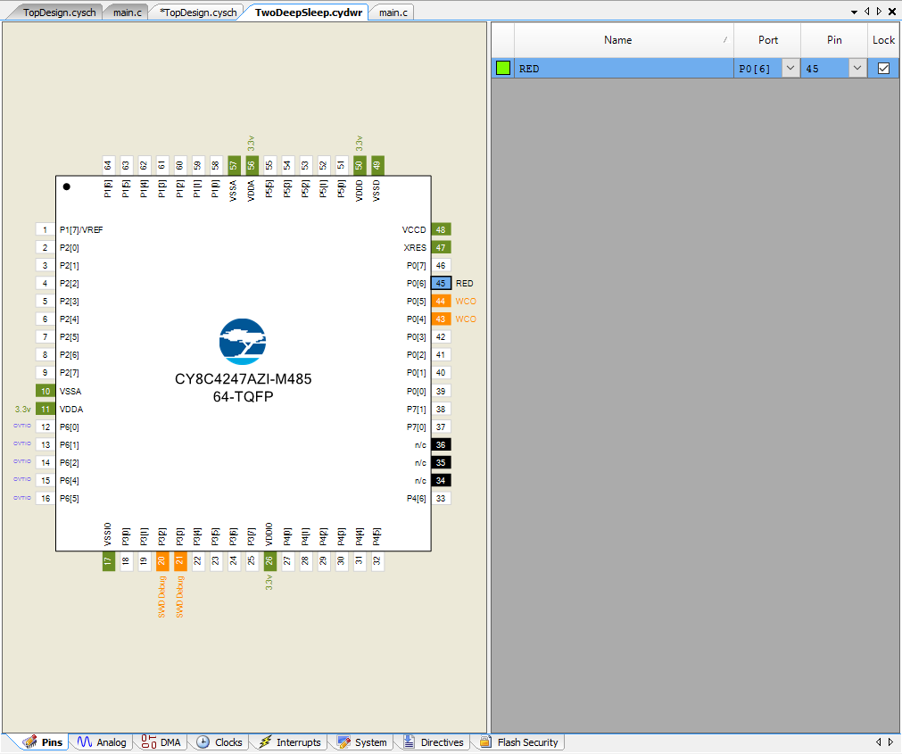
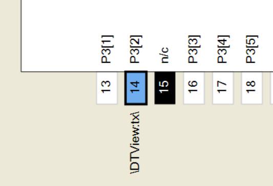
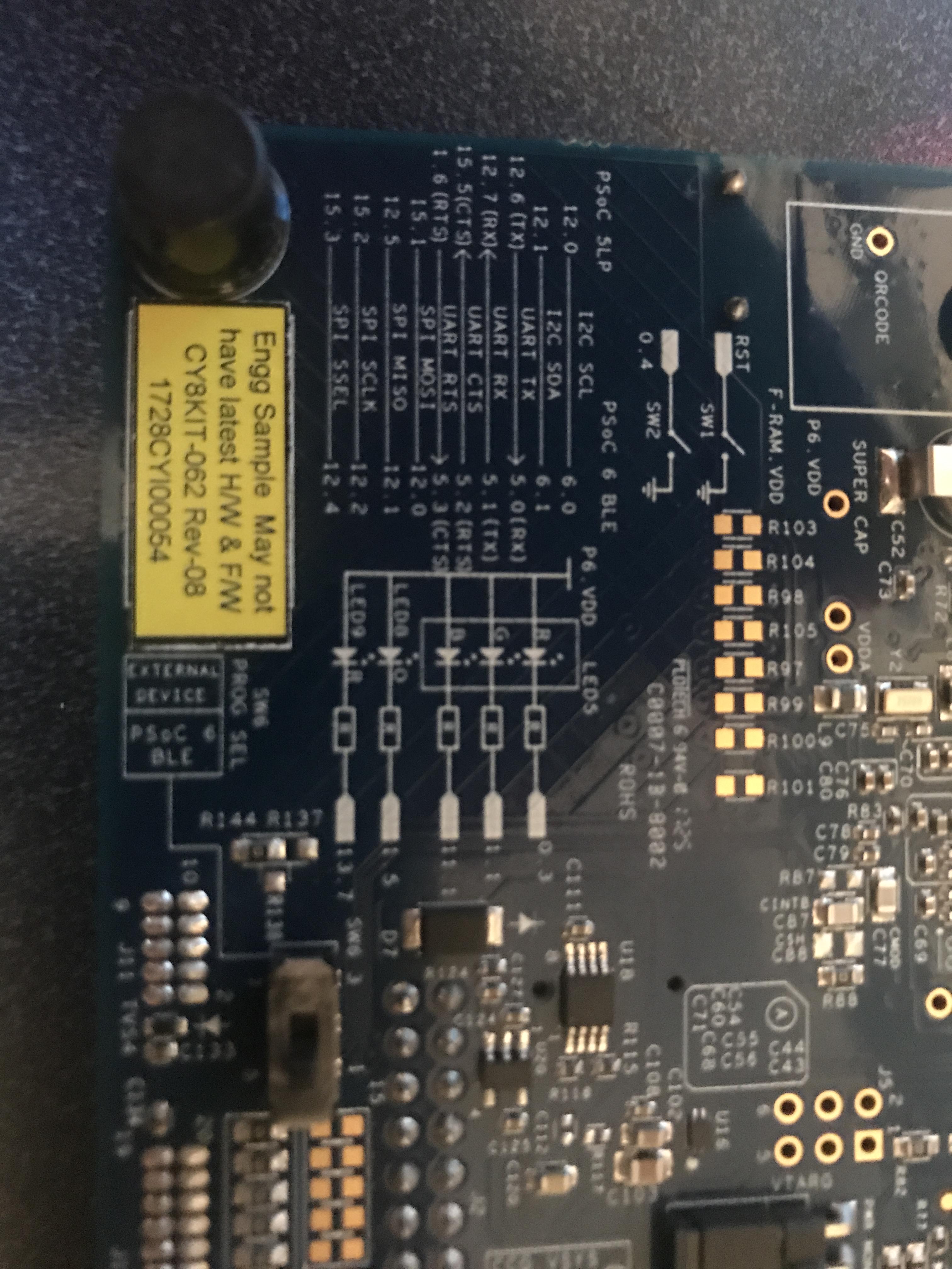
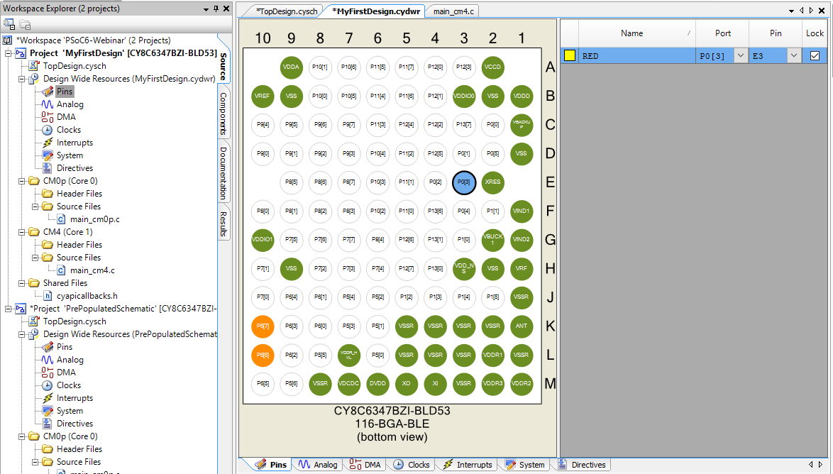
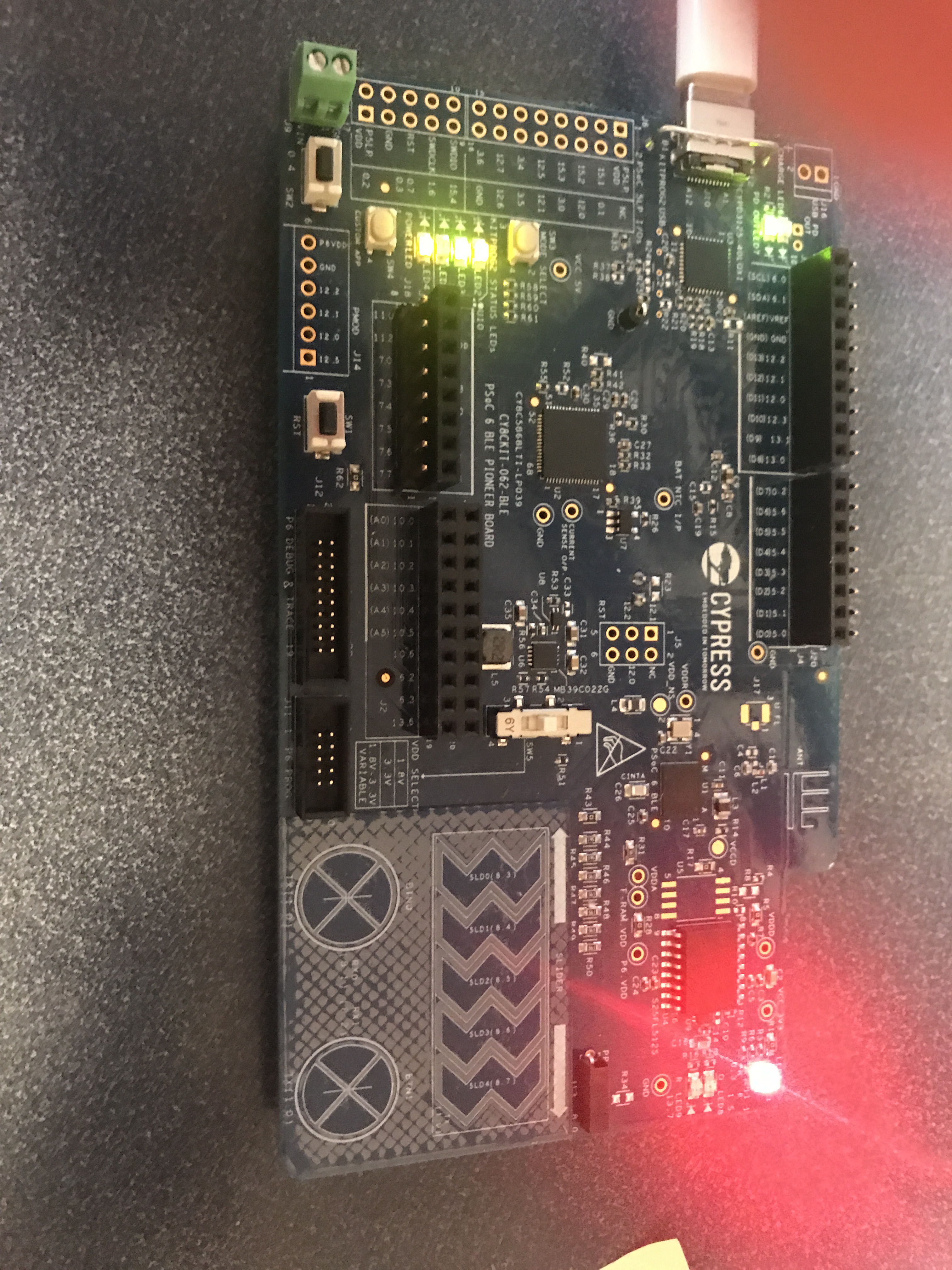
What pins on the PSoC 6 BLE is the UART attached to? Well… if you turn over your CY8CKIT-062-BLE you will find a little map that show that the PSoC 6 BLE UART is attached to the PSoC 5LP UART. The PSoC 5LP is programmed with the KitProg2 firmware.
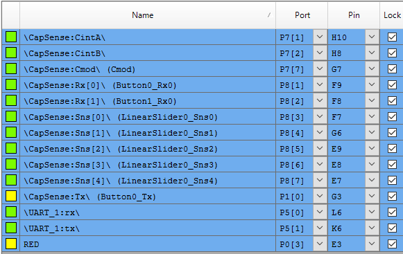
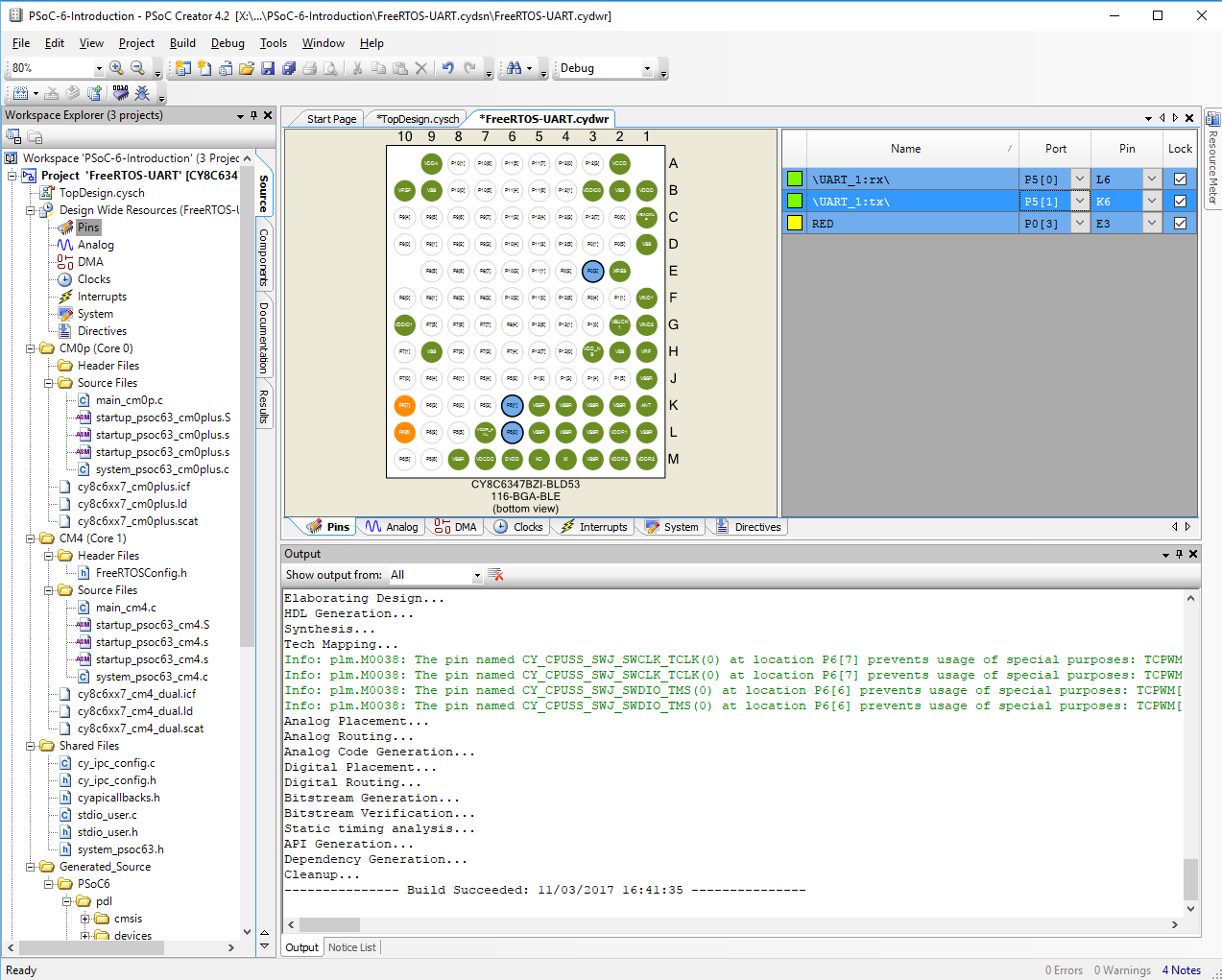
To attach those pins in your firmware you just double click on the “Pins” tab in the DWR. Then you can select “Port” for the UART RX and TX. Look at the picture below.
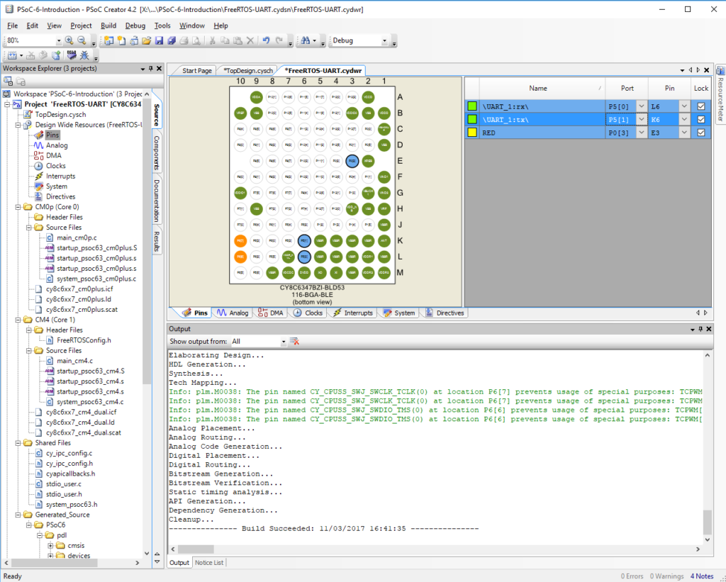
Now that I have all of that done, I run “Build->Generate Application” to get all of the new settings into my project.
Create the UART Test Firmware
The next step in making the printf work is to “retarget” it to the UART we just put in the schematic. Open “stdio_user.h” and add “include <project.h>” (line 130) and change IO_STDOUT_UART and IO_STDIN_UART to be UART_1_HW. The name “UART_1” on lines 136-137
#include <project.h>
#include "cy_device_headers.h"

/* Must remain uncommented to use this utility */
#define IO_STDOUT_ENABLE
#define IO_STDIN_ENABLE
#define IO_STDOUT_UART      UART_1_HW
#define IO_STDIN_UART       UART_1_HW
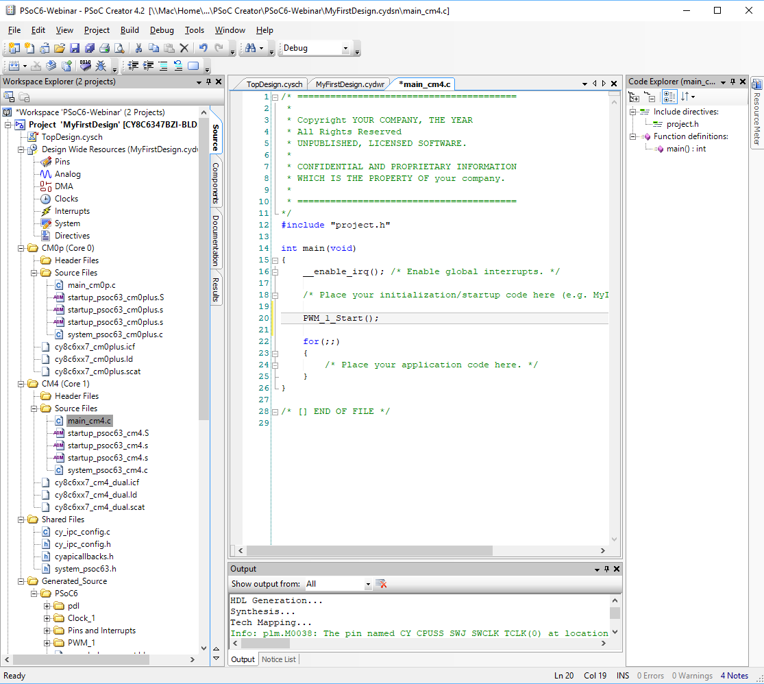
Now edit your main_cm4.c to:
- Turn on the UART with UART_1_Start() on line
- Then a couple of printfs lines 24-25
Note that “\033[2J\033[H” is just a VT100 escape sequence for clear screen and go home.
#include "project.h"
#include <stdio.h>

int main(void)
{
    __enable_irq(); /* Enable global interrupts. */

    /* Place your initialization/startup code here (e.g. MyInst_Start()) */

    PWM_1_Start();
    UART_1_Start();

    printf("3[2J3[H"); // Clear Screen
    printf("Test\r\n");


    for(;;)
    {
        /* Place your application code here. */
    }
}
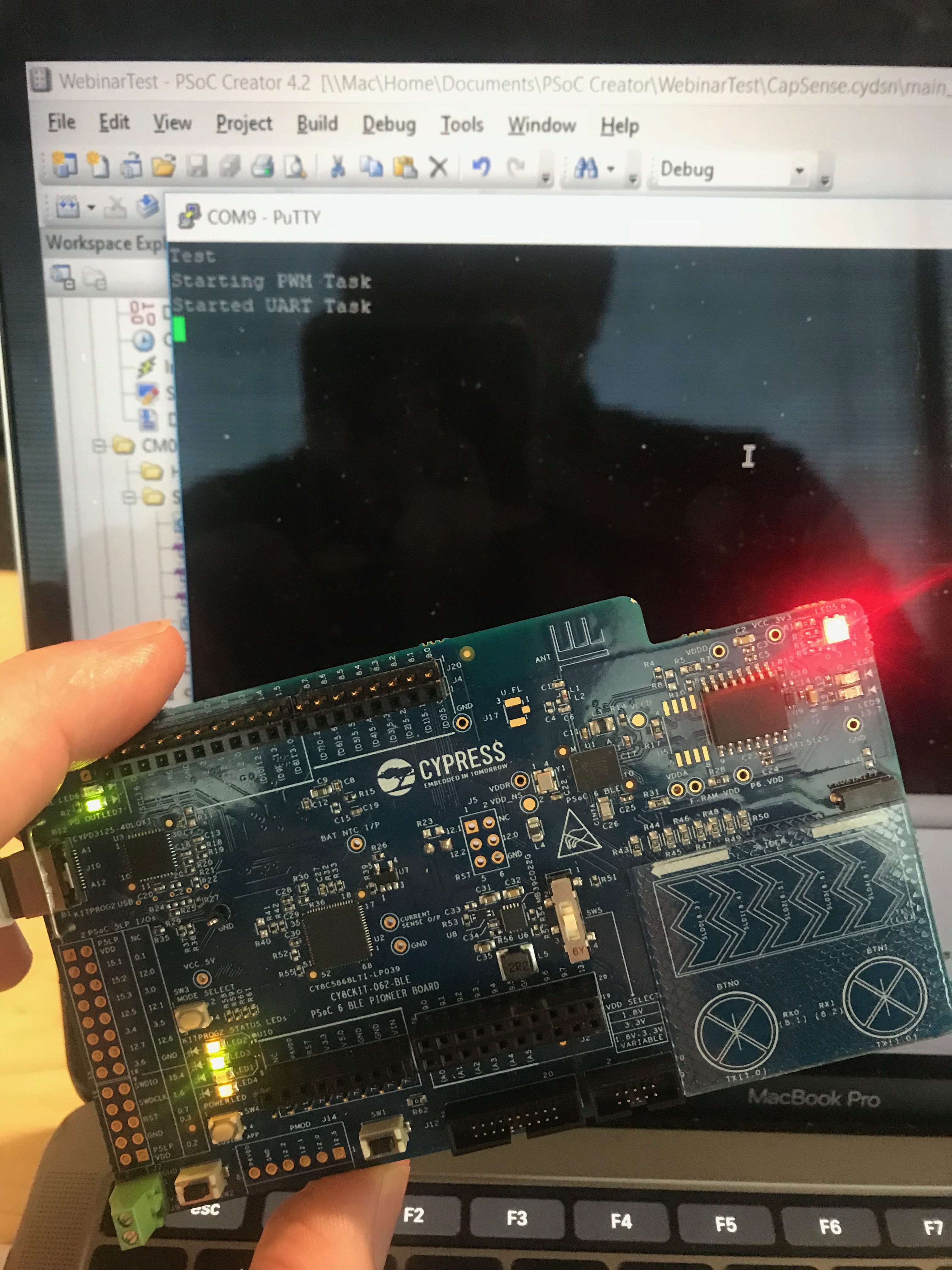
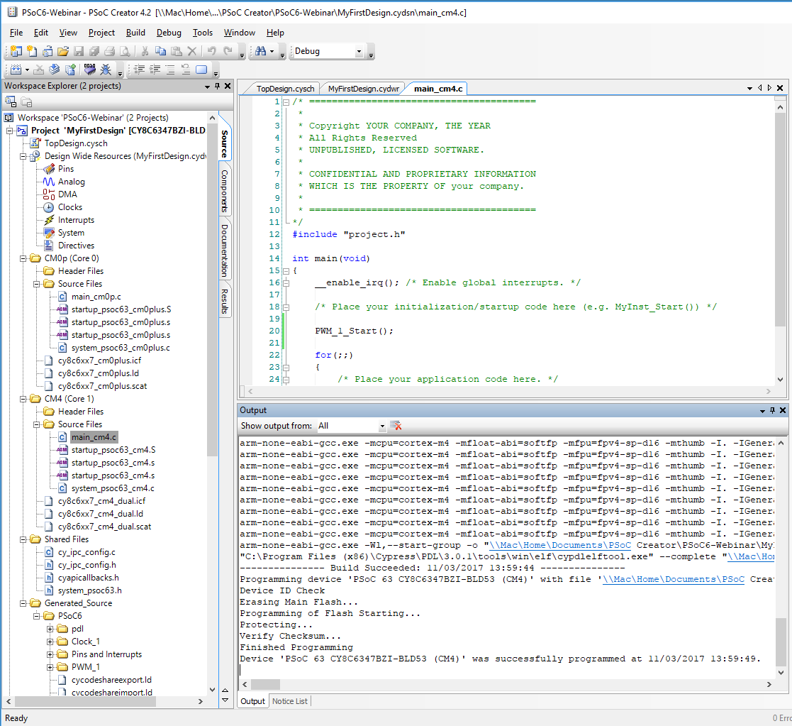
Program and Test the Debug UART
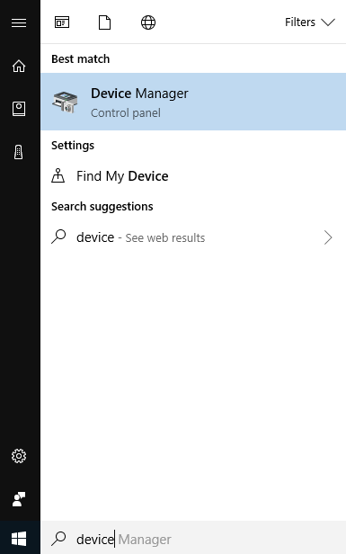
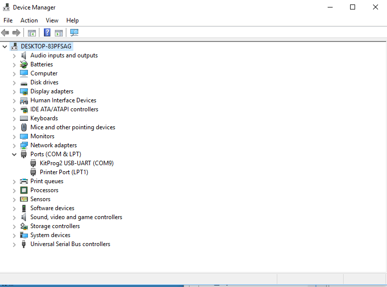
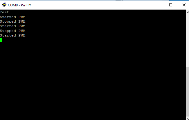
You need to figure out which com port that the KitProg2 is attached to. To do this run the device manager by pressing the “windows” button then typing “device manger”
Click on ports. Then you can see that the programmer is “KitProg2” and that the UART is attached to COM9 (everyone will have a different number)
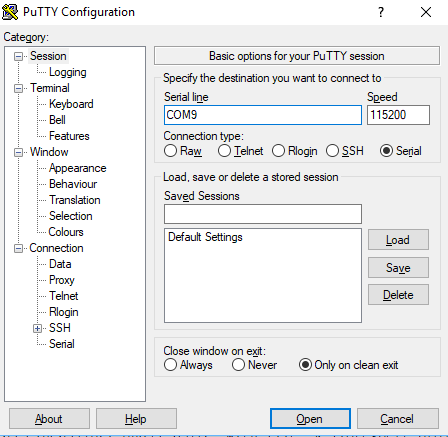
Run Putty (or your favorite terminal program)
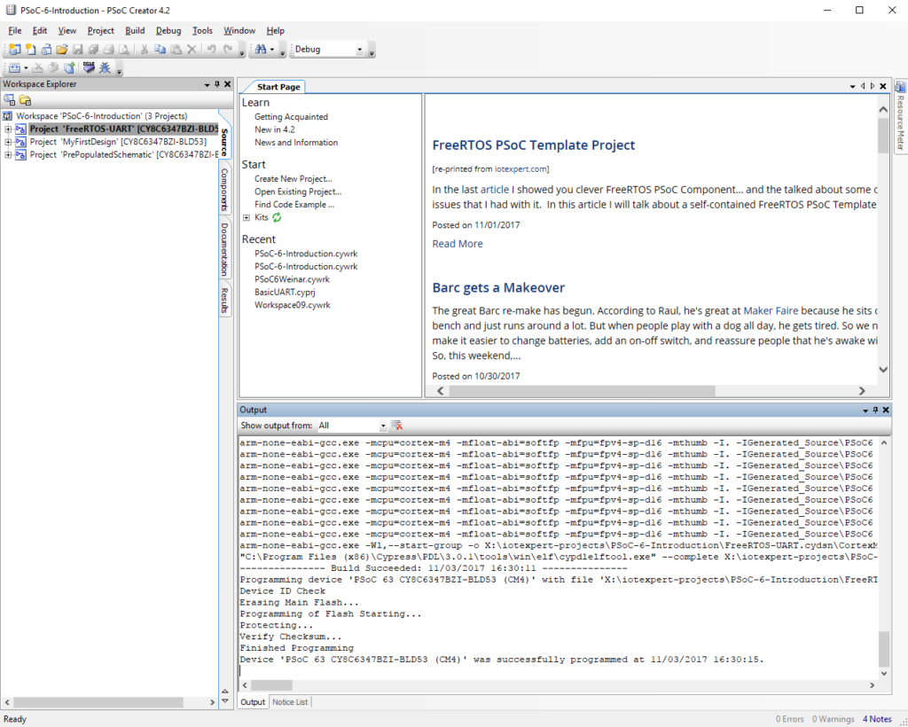
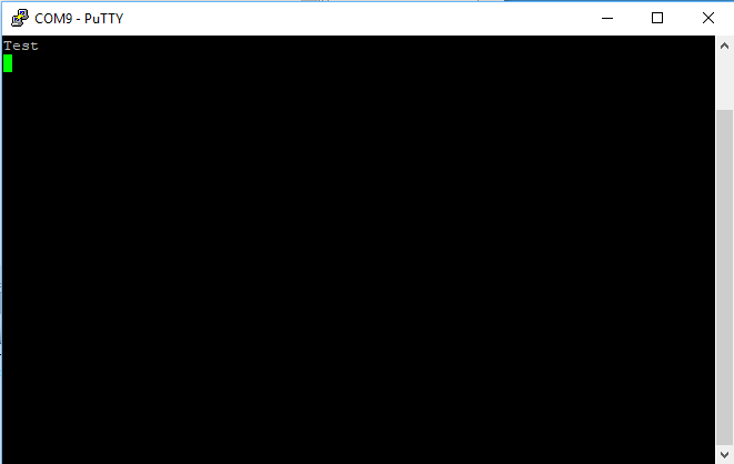
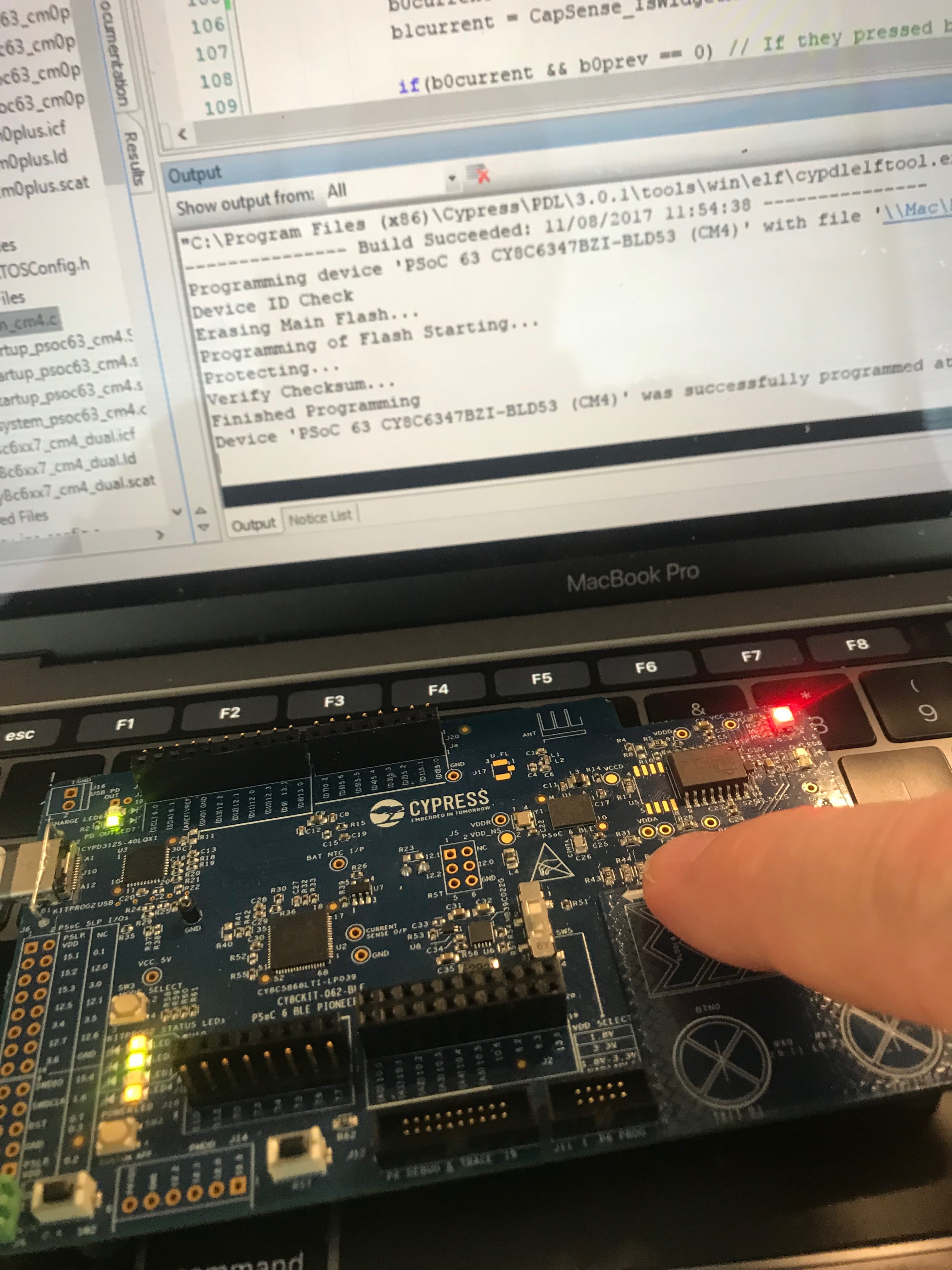
Press the program button on PSoC Creator and you should see your test print
Modify firmware for FreeRTOS
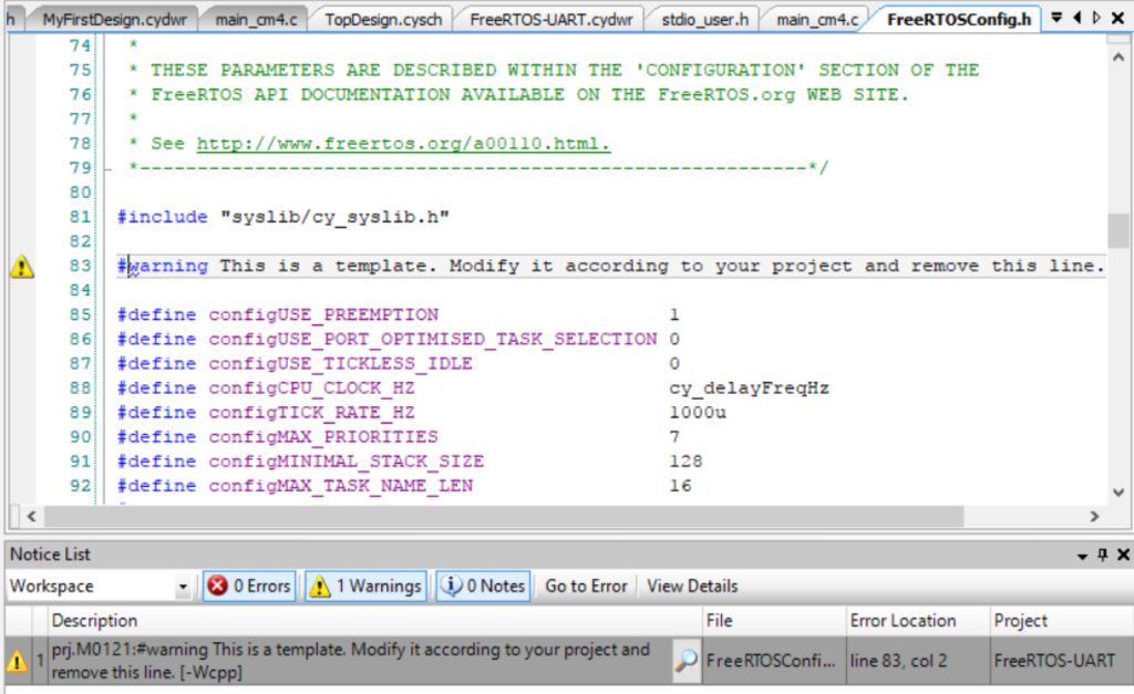
When I look out the output window from the previous step you can see that there is a warning message from FreeRTOS. Lets fix that warning (by deleting line 83). While we are at it, lets change the heap size to 48K (48*1024)
Now lets turn on FreeRTOS. Double click on main_cm4.c to open it in the code editor.
Add the following firmware to your project.
The uartTask is function that FreeRTOS uses to create a Task. This task will control the uart. (which is amazingly enough why I named it uartTask)
- The function call “setvbuff” turns of buffering on stdin… which means every character will immediately come through to your program
- getchar just gets a character from the terminal
- the ‘s’ and ‘S’ will start and stop the PWM (more to follow)
In main I
- Create a task for the uartTask (line 56)
- Start FreeRTOS (line 57)
/* ========================================
 *
 * Copyright YOUR COMPANY, THE YEAR
 * All Rights Reserved
 * UNPUBLISHED, LICENSED SOFTWARE.
 *
 * CONFIDENTIAL AND PROPRIETARY INFORMATION
 * WHICH IS THE PROPERTY OF your company.
 *
 * ========================================
*/
#include "project.h"
#include <stdio.h>
#include "FreeRTOS.h"
#include "task.h"

// uartTask - the function which handles input from the UART
void uartTask(void *arg)
{
    (void)arg;
    char c;
    setvbuf(stdin,0,_IONBF,0);
    while(1)
    {
        c = getchar();
        switch(c)
        {
            case 's': // Stop the PWM
                printf("Stopped PWM\r\n");
                Cy_TCPWM_PWM_Disable(PWM_1_HW,PWM_1_CNT_NUM);

            break;
            case 'S': // Start the PWM
                printf("Started PWM\r\n");
                Cy_TCPWM_PWM_Enable(PWM_1_HW,PWM_1_CNT_NUM);
                Cy_TCPWM_TriggerStart(PWM_1_HW, PWM_1_CNT_MASK);
            break;
        }
    }
}


int main(void)
{
    __enable_irq(); /* Enable global interrupts. */

    /* Place your initialization/startup code here (e.g. MyInst_Start()) */

    PWM_1_Start();
    UART_1_Start();

    printf("3[2J3[H"); // VT100 Clear Screen
    printf("Test\r\n");

    // Mask a FreeRTOS Task called uartTask
    xTaskCreate(uartTask,"UART Task",configMINIMAL_STACK_SIZE,0,3,0);
    vTaskStartScheduler();  // Will never return

    for(;;) // It will never get here
    {
    }
}
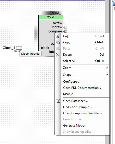
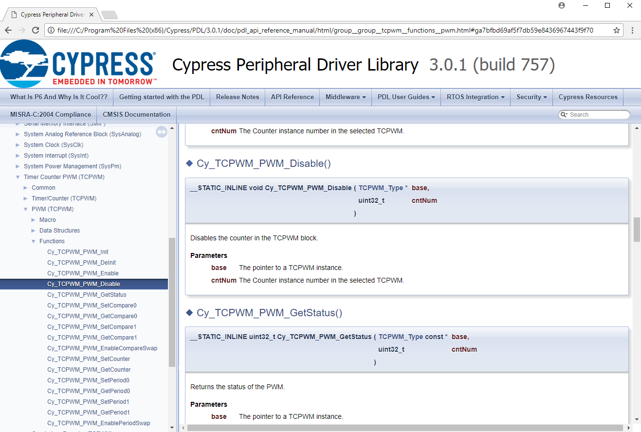
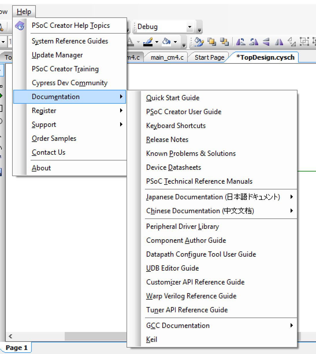
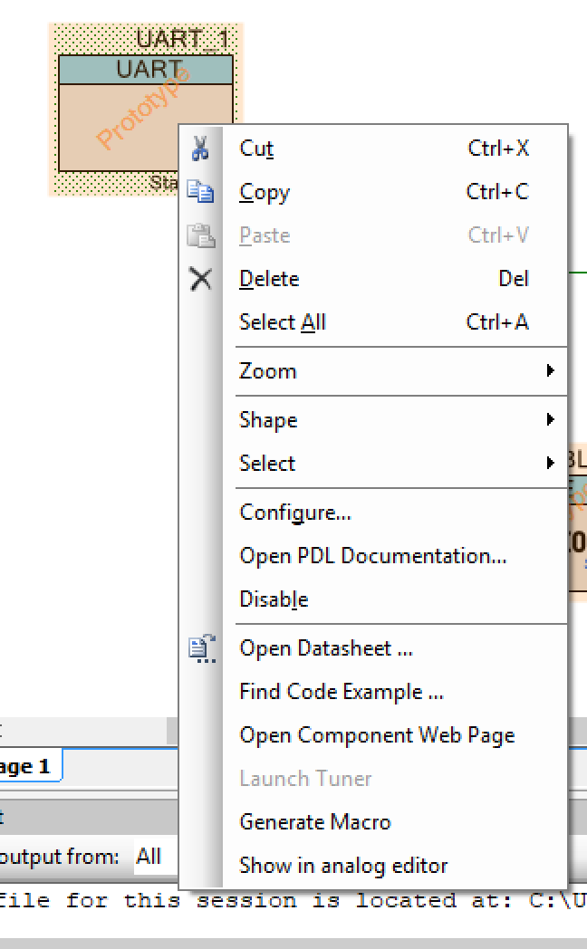
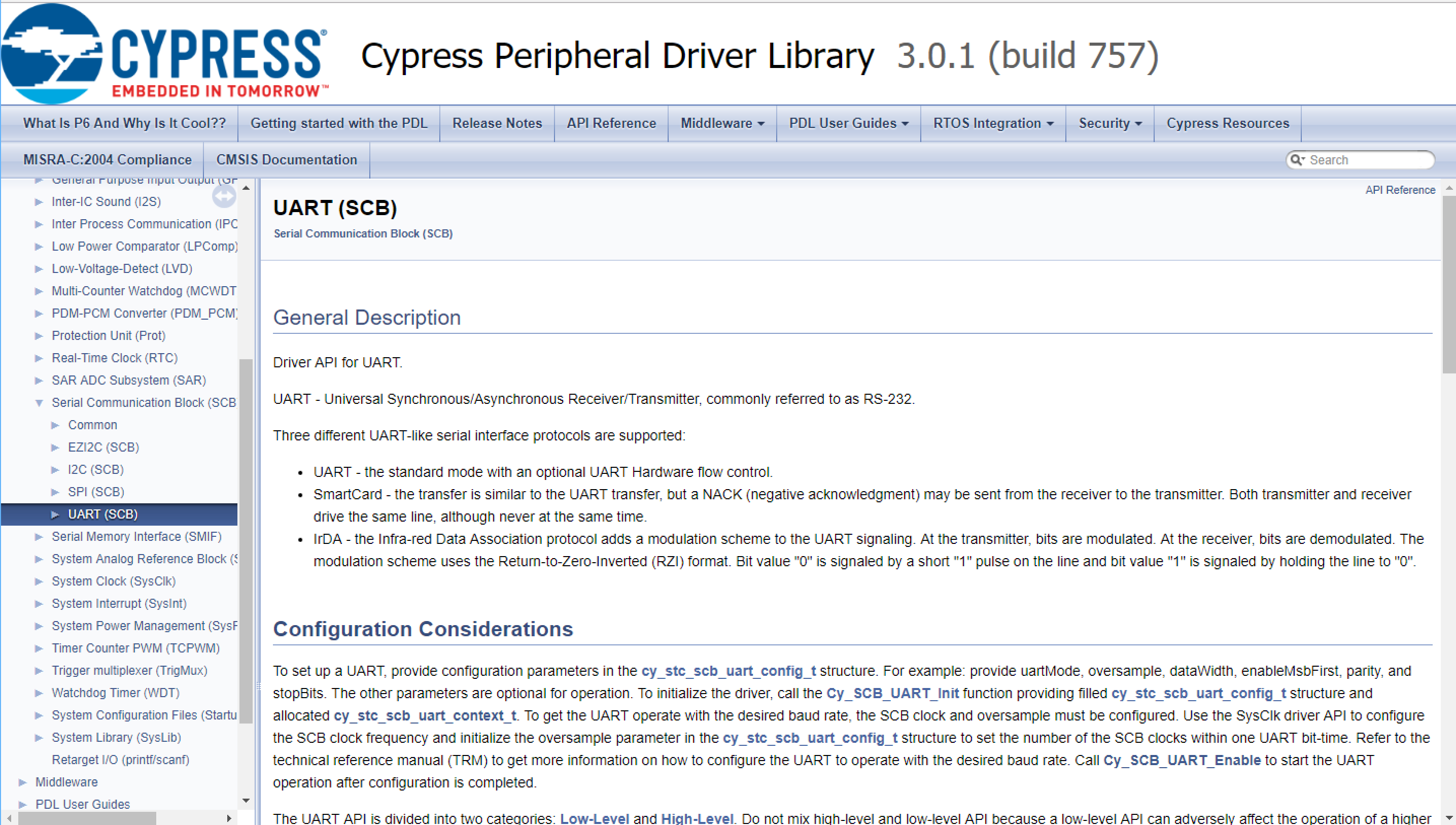
How did I figure out how to start/stop the PWM? To find the documentation for “PDL” aka the Peripheral Driver Library, you can right click on the component in the schematic and select “Open PDL Documentation”
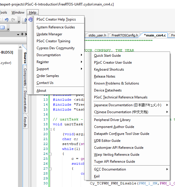
Or you can open “Help –> Documentation –> Peripheral Driver Library”
In the documentation I can see all kind of functions, including “Cy_TCPWM_PWM_Disable”

Program and Test
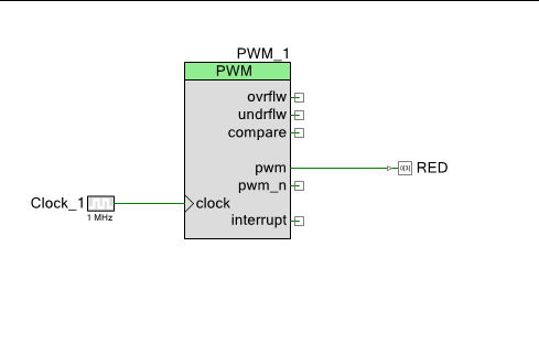
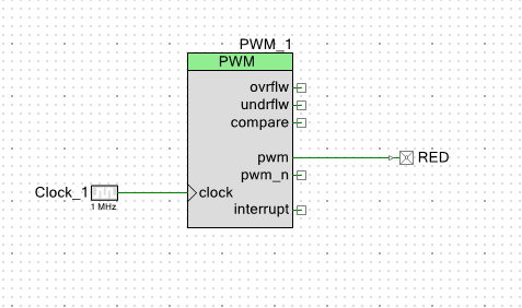
A Tour of PDL for the TCPWM
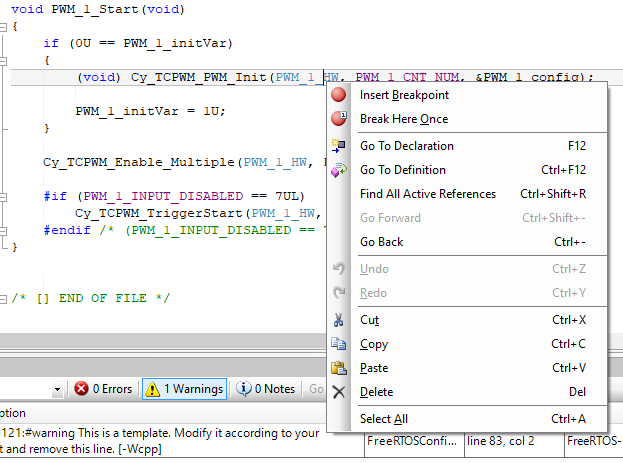
How did I figure out that the TCPWM_Type *base should be “UART_1_HW”? ….. well …. You might ask yourself, “What does PWM_1_Start()” do? It just calls PDL start function. OK… so what does that do? To find out you can right click on the “PWM_1_Start” function and select “Go To Definition” which will take you to the source code.

You will end up in a file called “PWM_1.c”. This file was created for you automatically by PSoC Creator. This function is really simple.
- If it has never been initialized then it calls init (lines 15-19)
- Then it enables the TCPWM (line 22)
- Then if there not an external pin on the PWM, then it causes a software trigger (line 25)
/*******************************************************************************
* Function Name: PWM_1_Start
****************************************************************************//**
*
*  Calls the PWM_1_Init() when called the first time and enables
*  the PWM_1. For subsequent calls the configuration is left
*  unchanged and the component is just enabled.
*
* \globalvars
*  \ref PWM_1_initVar
*
*******************************************************************************/
void PWM_1_Start(void)
{
    if (0U == PWM_1_initVar)
    {
        (void) Cy_TCPWM_PWM_Init(PWM_1_HW, PWM_1_CNT_NUM, &PWM_1_config);

        PWM_1_initVar = 1U;
    }

    Cy_TCPWM_Enable_Multiple(PWM_1_HW, PWM_1_CNT_MASK);

    #if (PWM_1_INPUT_DISABLED == 7UL)
        Cy_TCPWM_TriggerStart(PWM_1_HW, PWM_1_CNT_MASK);
    #endif /* (PWM_1_INPUT_DISABLED == 7UL) */
}
So, you might ask yourself what is “PWM_1_HW”? Well this is just the base address of the registers for the PWM_1. Lets follow that. Right click on it and go to definition.
This will take you to PWM_1.h and you will see PWM_1_HW is setup as PWM_1_TCPWM_HW. What is that? Well do the right click thing again and find out.
/***************************************
*           API Constants
***************************************/

/**
* \addtogroup group_macros
* @{
*/
/** This is a ptr to the base address of the TCPWM instance */
#define PWM_1_HW                 (PWM_1_TCPWM__HW)

/** This is a ptr to the base address of the TCPWM CNT instance */
#define PWM_1_CNT_HW             (PWM_1_TCPWM__CNT_HW)

/** This is the counter instance number in the selected TCPWM */
#define PWM_1_CNT_NUM            (PWM_1_TCPWM__CNT_IDX)

/** This is the bit field representing the counter instance in the selected TCPWM */
#define PWM_1_CNT_MASK           (1UL << PWM_1_CNT_NUM)
/** @} group_macros */

#define PWM_1_INPUT_MODE_MASK    (0x3U)
#define PWM_1_INPUT_DISABLED     (7U)
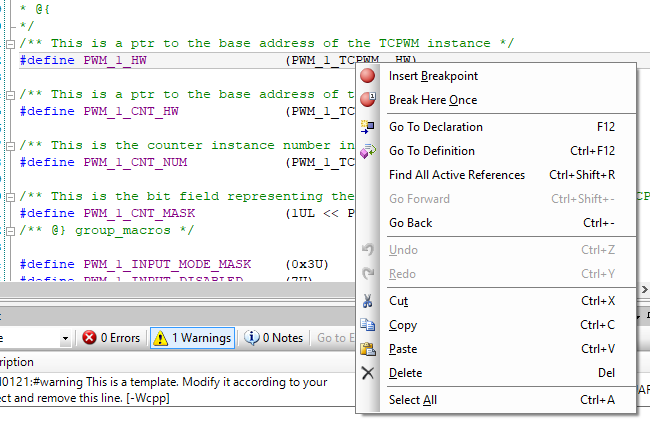
This will take you to “cyfitter.h” which is the output of the place and route. It tell you that PWM_1_TCP is really TCPWM0
/* PWM_1_TCPWM */
#define PWM_1_TCPWM__CNT_HW TCPWM0_CNT0
#define PWM_1_TCPWM__CNT_IDX 0u
#define PWM_1_TCPWM__HW TCPWM0
#define PWM_1_TCPWM__IDX 0u


