Summary of the PSoC4 Boot Sequence
In the previous post I took you through the first part of the PSoC4 Boot Sequence. I traced from the power on of the chip to the beginning of the “Reset()” function. In this post I will trace the steps that were required to get the reset vector and stack pointer set and programmed into the flash of the PSoC4 at the right place.
We know that you program the chip with a hex file which is essentially a file with a list of addresses and values. But how to you get a hex file? And how do you get the Reset Vector and Stack Pointer into the hex file? In order to create a hex file there are several steps required.
- Compile C –> Assembly Listing File then Assemble listing –> Objectfiles
- Link object files –> into ELF file
- Convert ELF –> Hex file
PSoC4 Boot Sequence: Compile and Assemble Program
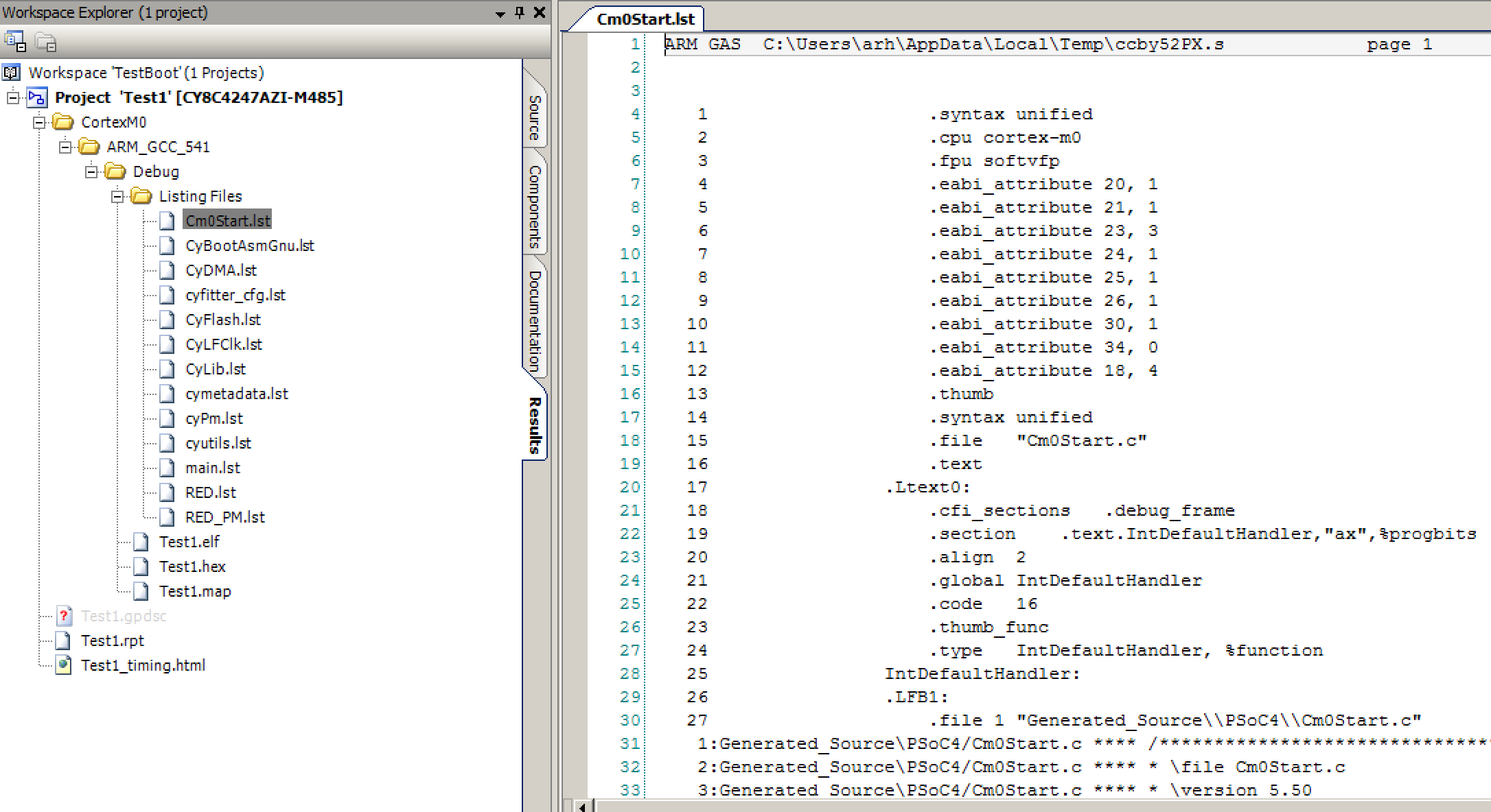
Each C file in your project is turned into an ARM assembly language program by the compiler. You can see the ARM assembly language programs in “.lst” files. You can find your project listing files by clicking on the “Results” tab in the workplace explorer then selecting the “listing files” folder under your project. In the screenshot below I am showing you the “Cm0Start.lst” which is the ARM assembly language file from the Cm0Start.c. You will notice that there is one listing file for each of the C files in your project.
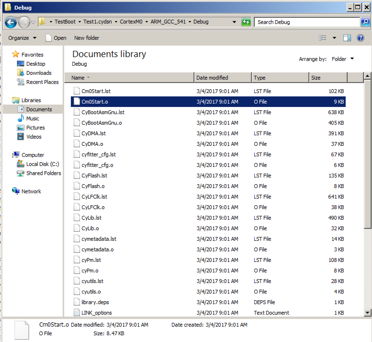
The next step in the process is for the Assembler to turns the listing files into object files. Each object file has the hex bytes that represent your program and data. It also defines which “section” that the code and data belong too. The .0 also has a list of symbols that it doesn’t know the address of e.g. the address of functions and data in other files. In order to see the object files you need to use the windows explorer (we don’t attach them to the workplace explorer)
PSoC4 Boot Sequence: Linker Configuration
The linker is responsible for:
- Combining all of the .o files into one file
- Assigning actual addresses for all of the symbols e.g. variables and functions
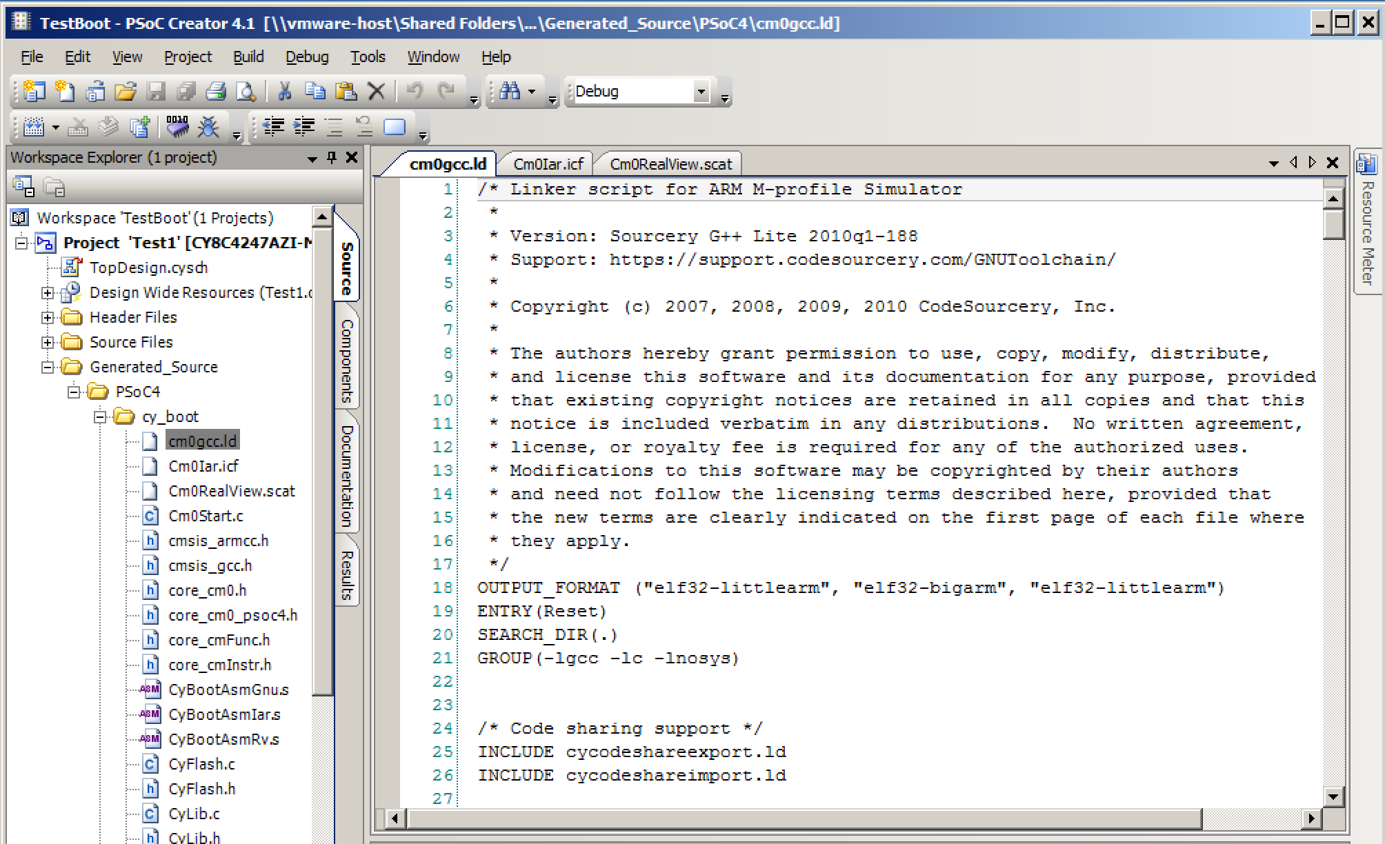
In order for the linker to do its job, it needs a linker script. Cypress supports three toolchains: GCC, ARM MDK and IAR. Each one of the toolchains has different syntax, form etc. for the linker script. This is painful, but it is made worse by the fact that the linker script language is rather esoteric. PSoC Creator makes a linker script for all three of the tool chains. You can find those files called “cm0gcc.ld” (the GCC linker file), Cm0Iar.icf (the IAR linker file) and Cm0RealView.scat (the MDK linker file) in the workspace explorer under Generated_Source–>PSoC4–>cy_boot
There is quite a bit going on in the linker file. In fact the GCC linker file for PSoC4M is 470 lines long. However, there are two basic commands in the linker file.
The “Memory” command which defines the address and size of the different types of memory in the system. Each block of memory is sometimes called a “region”, but the Linker words “region” and “section” and “segment” are used somewhat erratically in the parlance. In this PSoC4M there is 128K of Flash that starts at address 0x00000000 and 16K of RAM which starts at address 0x20000000. You can see the “Memory” command on lines 29-33 of the GCC linker script.
The second big command in the linker file is “SECTIONS”. After the sections command there is a list of [input] section names and where they belong (aka their address). When you look around on the internet you will find that sometimes the word “section” is used interchangeably with the word “segment”. Unfortunately there does not appear to be a canonical definition of either of these words. There are three main section/segments
- bss – this section contains variables which should be initialized to zero before main starts
- data – this section contains variables which need to be initialized to some specific value
- text – this section contains your program
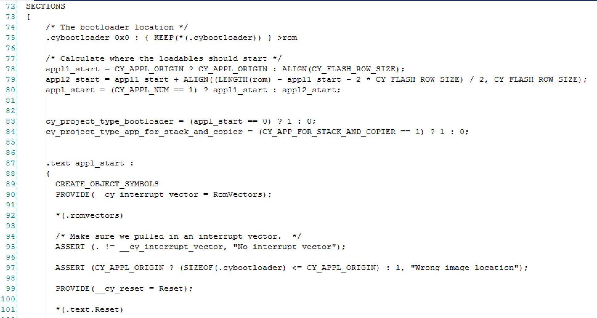
Here is a screenshot of the part of the GCC linker file that includes the definition of where the PSoC4 ARM exception vectors are located. This starts on line 72 where the “SECTIONS” command is issued.
The section command defines the a list of sections and the address of the sections. Inside of the linker there is an “address pointer” which keeps track the current address in the system. As it loads sections into the program it increments the address pointer so that it knows the final address of symbols.
In the above listing you see on line 87 that a section called “.text” belongs starting at address “appl_start”. The linker code on lines 75–>80 is used to support bootloading programs with multiple application. However, in this case we have only one application and no bootloader. As a result nothing is loaded and “appl_start” is set to 0x00000000 which is also known as the first location in Flash. Line 92 tells the linker to put the code in the section “*.romvectors” next. Now we need to find the code that is marked in some .c file as belonging to the section “romvectors”. I will come back to the linker script in a later article.
Cm0Start.c the Heart of the PSoC4 Boot Sequence
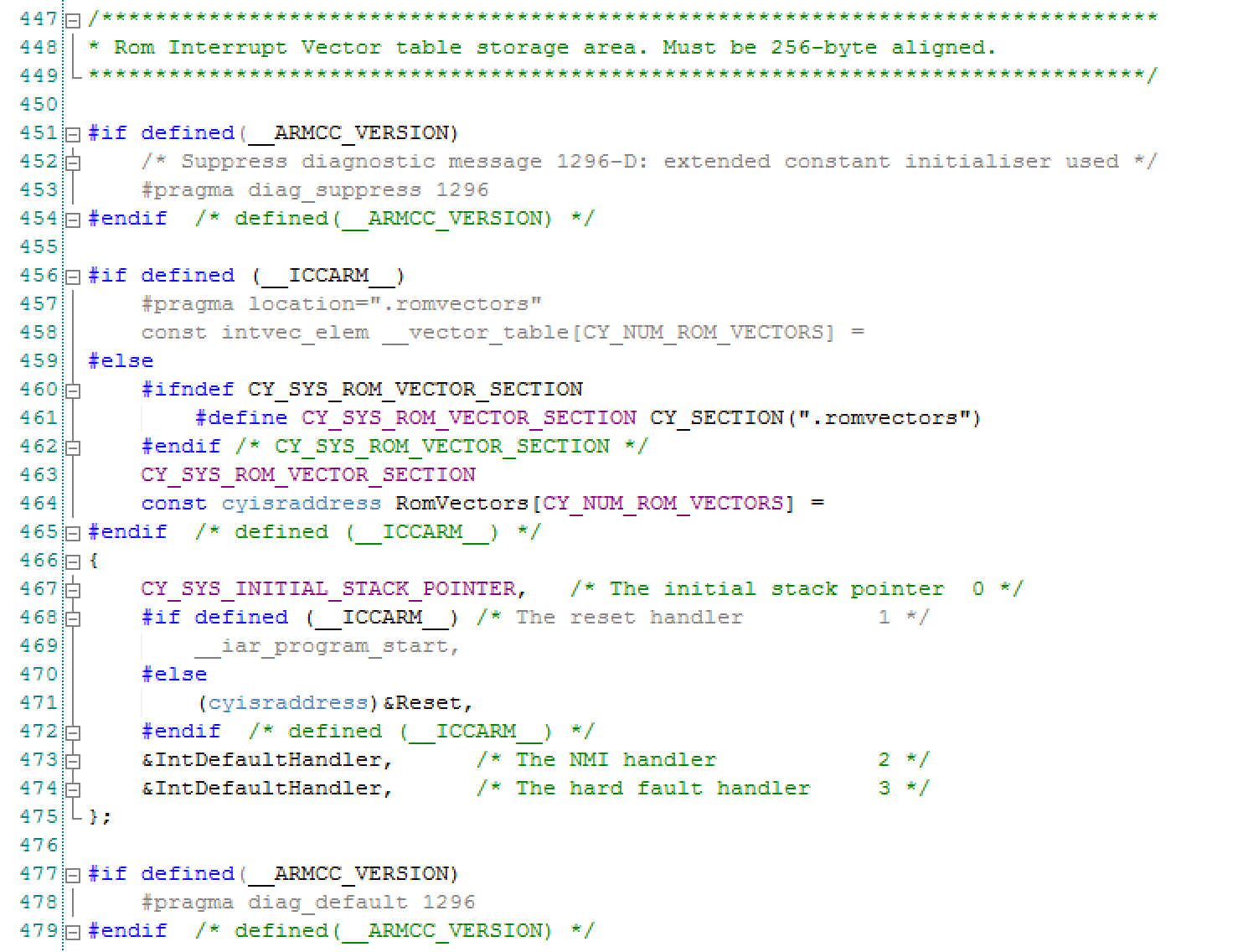
After digging through the beginning of the linker script and putting a breakpoint on the reset vector we know that the vector table is in a section named “romvectors” and we know that the 2nd entry in the table is the address of the function “Reset()”. So that leaves us with the question: Where are the “romvectors” defined? After using the PSoC Creator search functionality I find this block of code.
That nested mess of #defines and #ifdefs is a bit intimidating… but it was all put there to support the three different compilers. If you boil it down, the first thing you will see is line 462 tells the compiler to put the next block of code into the “.romvectors” section. Bingo! that is exactly what we were looking for. Then on line 464 you can see that we define an array of type “cysisraddress”. It turns out that “cyisraddress” is just a function pointer. OK.
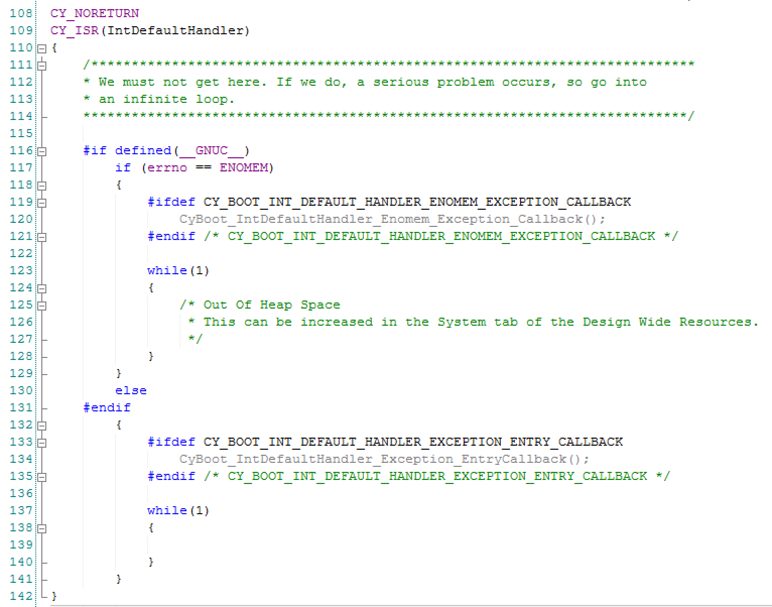
Now dig a little bit more and you can see that line 467 defines the address of the initial stack pointer as CY_SYS_INITIAL_STACK_POINTER. This address is the last location in the RAM. Then on line 471 we put the address of the Reset() function, then we put in two entries for the NMI and hard fault handers. The “IntDefaultHandler” is an infinite while(1){} which hangs the processor. This function is also in the Cm0Start.c file.
Stack Pointer
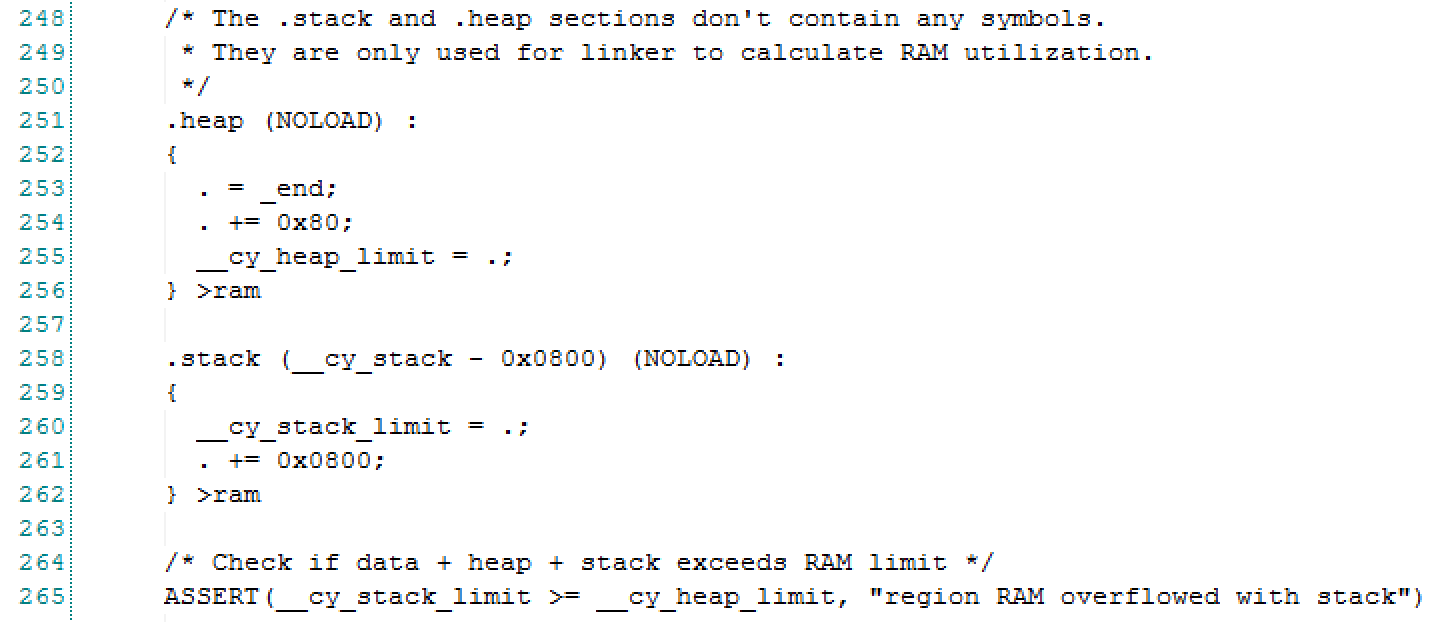
Earlier I said “.. the address of the initial stack pointer. This address is the last location in the RAM.” How does that get to be? Well if you hover over CY_SYS_INITIAL_STACK_POINTER you will find that it is a #define for the symbol “__cy_stack”. Then when you look in the linker script you will find:
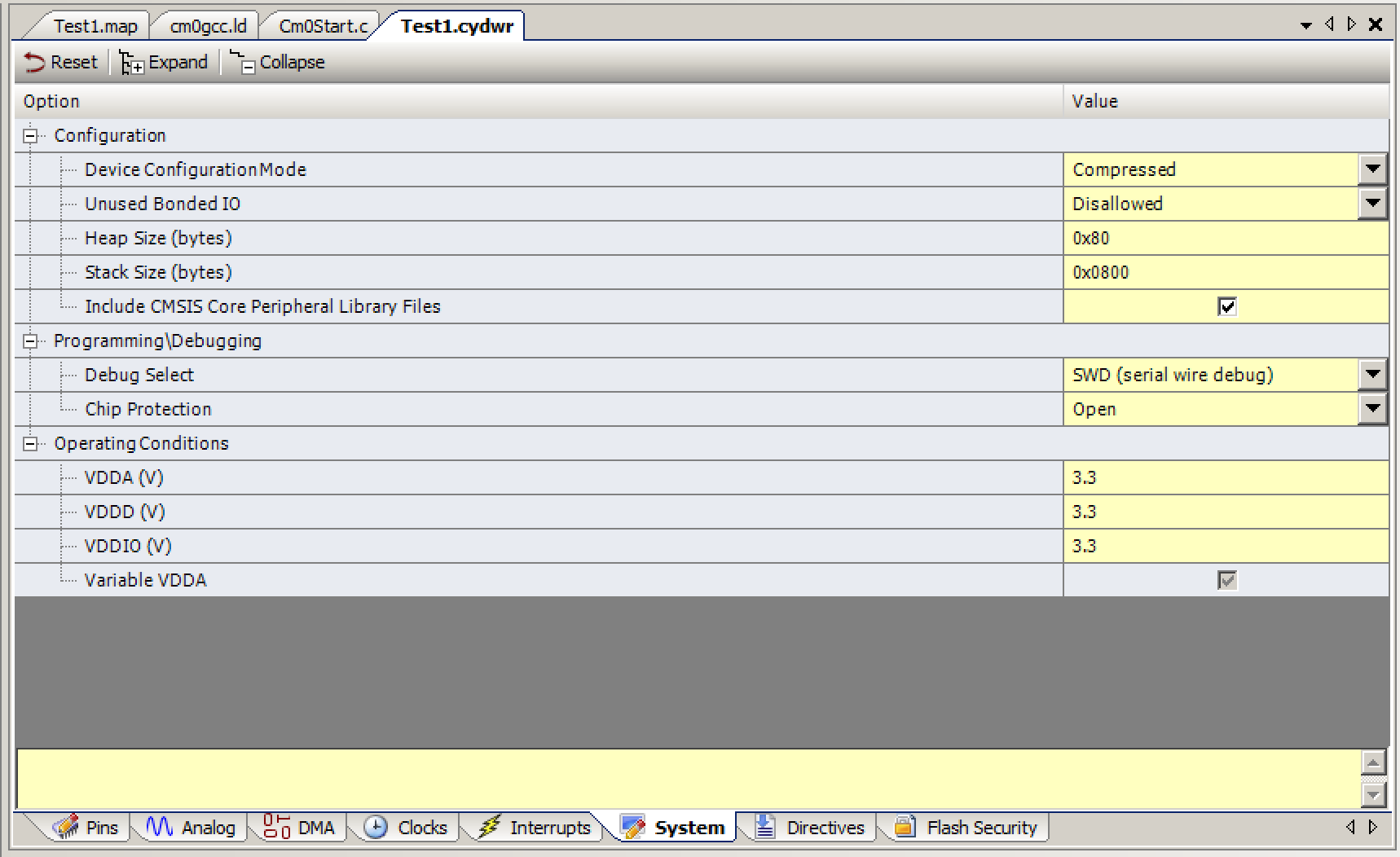
You can also see that the end of the heap is defined as the address of __cy_stack – 0x800. The 0x800 must be the size of the stack… and it is… you define it in on the system resources tab of the “design wide resources”
The final thing to look at with regards to the stack is linker file definition of the stack (and heap). On line 258 you can see that the stack starts at the address __cystack – 0x800. This address is also known as the end of the RAM minus the size of the stack (remember that in ARM the stack builds down towards lower addresses)
Test1.map
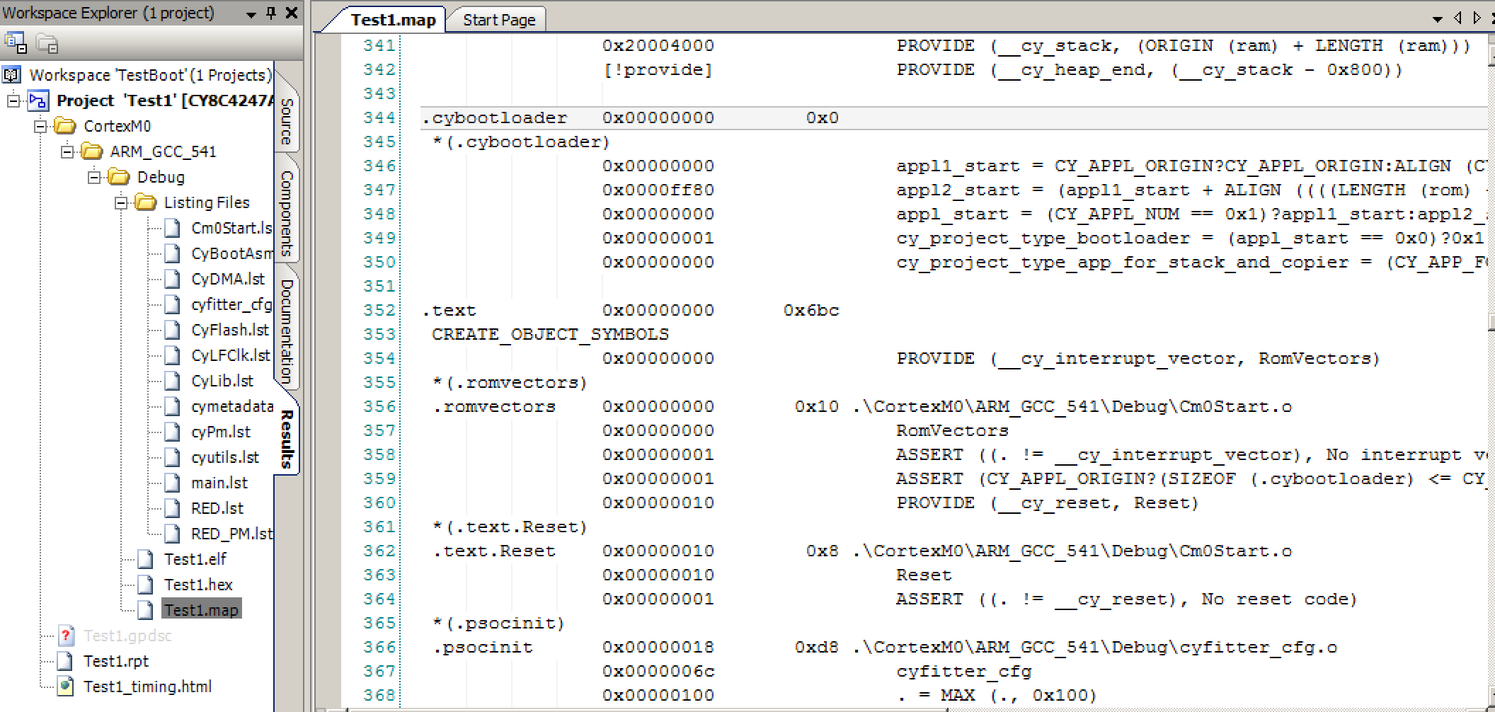
The last link in the chain is the linker map file. You can find that file in the Test1–>CortexM0–>ARM_GCC_541–>Debug–>Listing Files directory. The map file is message output file of the linker. You can see the final resting place of all of the symbols. In the screenshot below you can see that the “.romvectors” segment started at address 0x0 and ended at address 0x10. This makes sense as there are 4x 4 byte addresses (stack pointer, reset vector, NMI vector, Hard Fault vector)
And the stack landed at 0x200038000 and ends at 0x20004000 which makes sense as we have 16K of SRAM aka 0x4000 bytes.
In the next post we will follow through the “Reset()” function and the initialization of the BSS&Data section as well as the C-Standard library.
Article
Description
PSoC4 Boot Sequence (Part 1) - Debugging to the Reset Vector
An introduction to the PSoC4 Boot Sequence
PSoC4 Boot Sequence (Part 2) - Creating the Exception Table using the Linker
Building the exception vector table
PSoC4 Boot Sequence (Part 3) - Preinitializing Variables before main()
Initializing BSS and Data
PSoC4 Boot Sequence (Part 4) - Linker trickery with __attribute_((constructor(101)))
Running initialize_psoc()
PSoC4 Boot Sequence (Part 5) - Initialize PSoC



2 Comments
Thanks for this series of articles, is good to know this topic but i haven’t seen a lot of post about this out there :).
Now a Off Topic question somewhat related to linker scripts: Some time ago i installed a newer ARM Toolchain (version 5.4), then set up Creator to use it instead of the toolchain installed with Creator (4.9) and had problems with the linker script (i can’t even compile the project), with the newer version (6.3.1) i can compile the project but can’t debug ;(.
How is decided what version of the ARM Toolchain ships with newer versions of PSoC Creator?
You are welcome.
The decision is by in large ad-hoc. There are a few guys on the team in the US and Europe who keep track… Then when there is something compelling there is a joint decision by the CTO Office, the PSoC Creator Manager and the Business Unit Manager. All that being said there has been extreme focus on PSoC6 the last year.