In the previous two Bus Pirate posts, I introduced the Bus Pirate and talked about the V3 version from Sparkfun, and I showed how to use the V3 version from Seeedstudio to read and write I2C commands into a Cypress FRAM.
Bus Pirate V4 is a complete redesign of the hardware. It combines the PIC microcontroller and FTDI USB/Serial bridge into a single chip (a PIC 24FJ256GB106). Mr. Lesnet also added 3.3v and 5.0v on board regulated voltages, and an onboard eeprom for extra storage. You can read more on the Dangerous Prototypes web page.
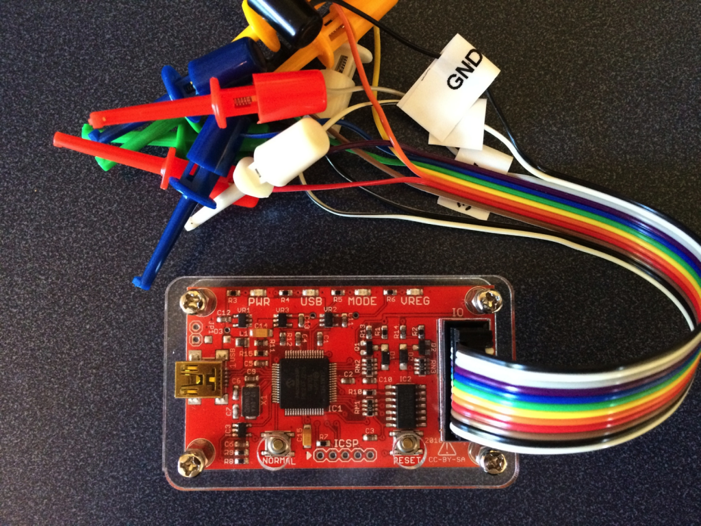
I also ordered the acrylic case (which is cool) as well as the V4 cable (which sucks compared to the V3 cable because the grabbers don’t match the cable color and are signals are unlabeled).
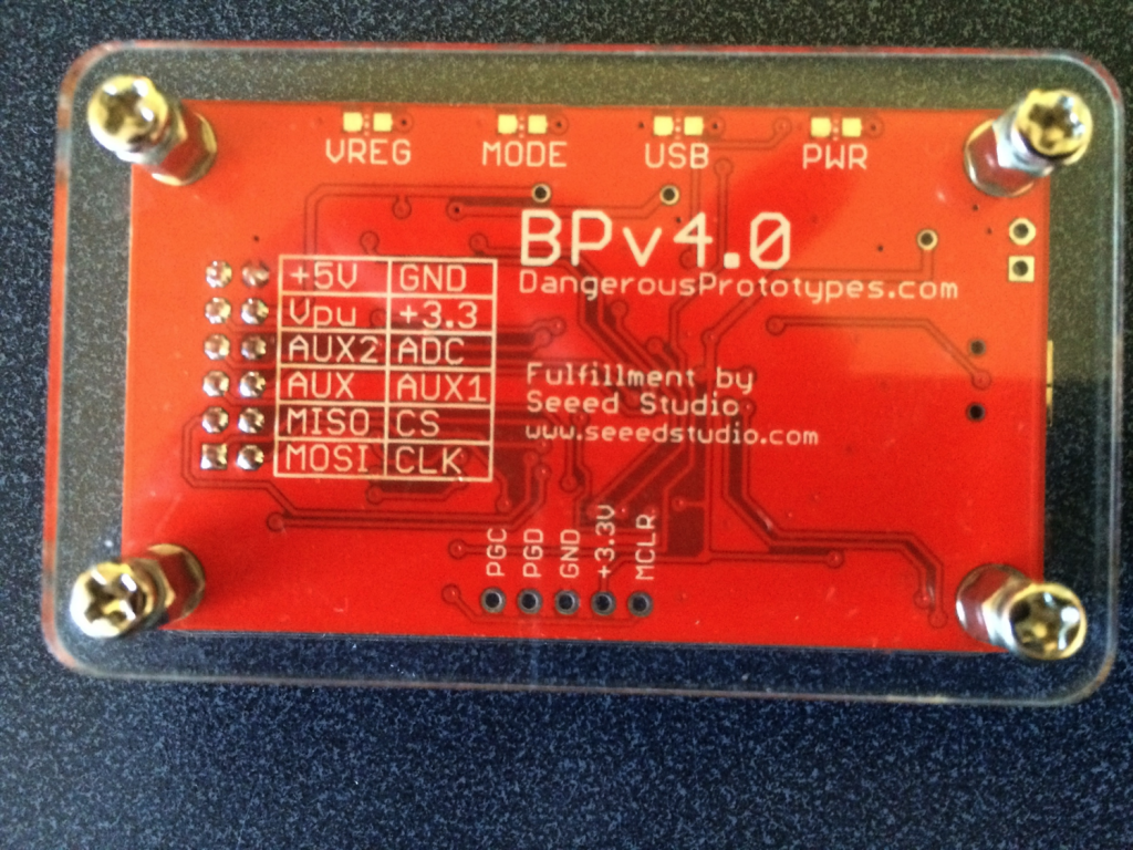
On the back of the board you can clearly see the right way to put a silkscreen on a board. Clear, sensible, legible.
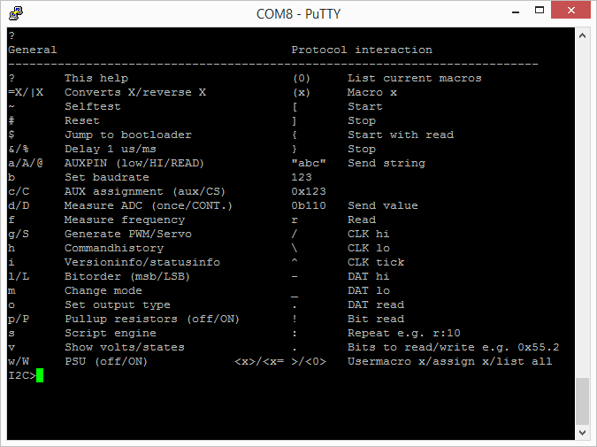
The first thing that I did was “?” to see what was new on the menu.
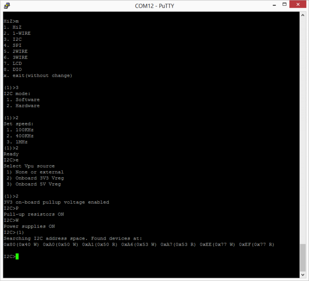
The next thing that I tried was putting the BP into I2C mode. This was similar to V3 with the exception that now there is a hardware driven I2c and it is capable of 1MHz operation. The other thing that has been added is a programmable onboard power supply. You can select either 3.3v or 5.0v by using the “e” command. The power supply can be turned on/off using “w” (off) and “W” (on).
Here is a screenshot of the schematic for selectable regulated pullup.
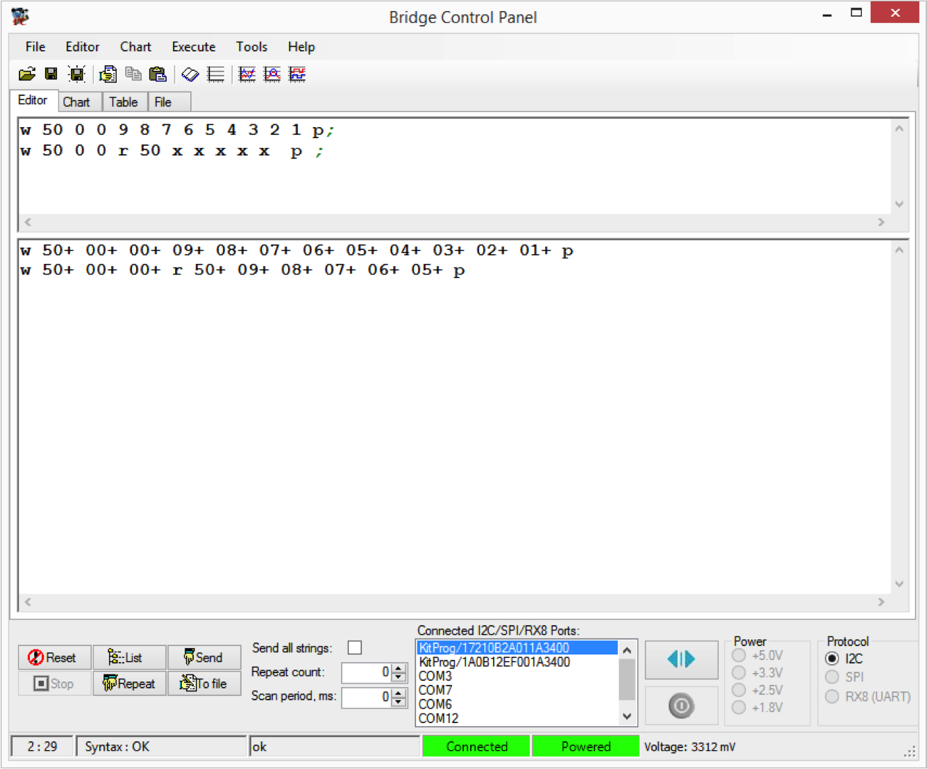
I was interested in trying the Bus Pirate I2C sniffer. To do this I used the onboard I2C bridge in the “KitProg” on the CY8CKIT042 and used the Cypress Bridge Control Panel (part of PSoC Programmer) to issue I2C commands to the FRAM on my test setup (which is the same as in the previous posts). In the example below I first issue a “Write, location 0x00, data 9,8,7,6,5,4,3,2,1” In other words fill up the first 9 locations in the FRAM with 9..1.
The second command issues a “write, location 0x00, Read the next 5 bytes (each “x” reads 1 byte)”.
In the 2nd part of the Bridge Control Panel you can see the actual commands that happened on the bus and the ACKs (“+”) and responses from the FRAM.
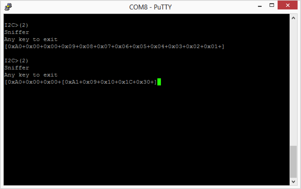
In the screenshot below you can see that the sniffer perfectly “sniffs” the first command. That is pretty cool… and a very useful function.
In the second case, you can see that the BP sniffer can see the write command perfectly and can read the first byte response from the FRAM perfectly, but does not read the other bytes correctly. Specifically it reads 0x10, 0x1c and 0x30 instead of 0x08, 0x07, and 0x06.
To debug this problem I plugged in my Tektronix MSO2024B logic analyzer to see if there was some problem with the I2C transactions. However, you can see from the screenshot below that the scope can read transactions perfectly. So, what is going on? I don’t know. But, at this point it seems clear that the sniffer is a bit flaky. At this point that is going to be a problem for another day.



No comment yet, add your voice below!