Summary
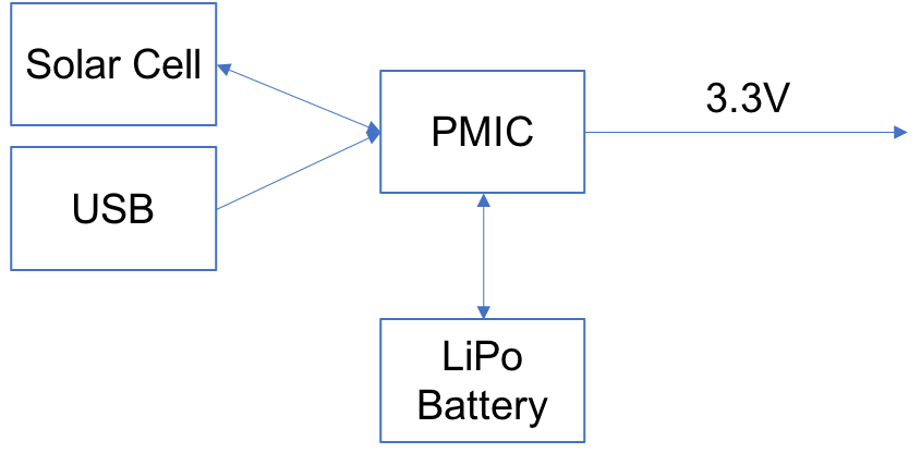
In the last Article I talked about my Mailbox problem. My original plan was to have this device powered with a coin cell. As I discussed the project with my lab assistant, Nicholas, he asked why it wasn’t going to be solar powered. I didn’t have a good answer for this question. This basic question led me down a multi-week deep dark rabbit hole. For a while (weeks?) I am going to write about my experiences building a solar power supply for my board. Ideally I want this architecture:
In words, I want to power the system at 3.3v from a battery, USB or a solar cells. And, I want the solar cell and/or the USB to charge the LiPo battery. It turns out that I don’t/didn’t know much about:
- Solar Cells
- Charging LiPo batteries – or in fact batteries
- Buck-Boost / Buck Convertors
- Super Capacitors
And it turns out that there is an unbelievably large number of PMIC combinations that might work. Unfortunately, Cypress does not make one. We do make an Energy Harvesting Boost Convertor, but nothing that can do battery charging. The last things that surprised me about this whole thing is that the normal maker suspects (Adafruit, SEEED Studio and Sparkfun) don’t really make good breakout boards that meet my architecture needs.
My current plan is to:
- Research, buy and evaluate “a bunch” of different evaluation kits from the usual suspects (Ti, Analog, Linear, ST and Maxim)
- Document a comparison of the offerings
- Write about charging batteries
- Write about solar cells (How you use them? Where do you buy them? How do you test them?)
- Write about buck-boost convertors
- Design the power supply for my IoT board
Solar Battery Charging PMICs
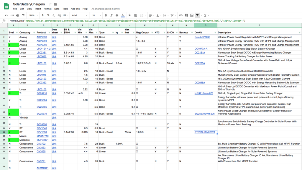
I started this whole process by making a google sheet with all of the characteristics that I care about. I made the sheet public so that you can see the current version.
If you look in the spreadsheet you will notice that there are some holes. And there are Im sure some missing rows. If you know the answer to any of the open questions, or have other PMICs you are interested in, please either make a comment on this Article or send me an email at engineer@iotexpert.com
Development Kits
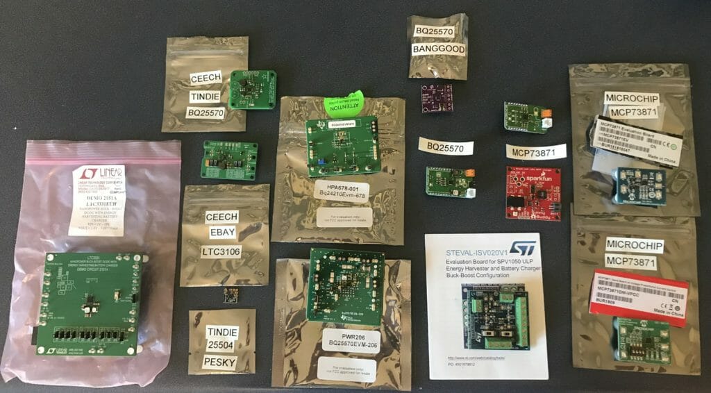
As you can see from the picture below, I have a bunch of development kits. Some were built by Semiconductor companies, some were built by third parties. I have chips from Analog, Linear, Microchip, TI and ST. There is one interesting company in China called Consonance (which I dont have boards for), In addition, Fujistsu Electronics also makes a IC that I don’t have yet.
In the picture you can see that I have LTC3331, LTC3106, TI BQ25507, TI BQ25570, TI BQ24210, Microchip MCP73871, ST SPV1050 … for now.
In the coming articles look for detailed instructions on these chips, starting with the LTC3331.
Article
Description
IoT Mailbox Introduction
An introduction to the long series of articles about creating a new IoT System.
IoT Mailbox: Solar Battery Chargers & System Power Supplies


4 Comments
wow, thiss is something I have had quite an interest in since a long time, though I also want my output to have 5V capability.
I think that is not a very unusual ask for such a circuit.
powered by Solar, or battery or DC input – charge the battery 3.3V Lipo/Li-Ion – the battery supplies power to generate 3.3V and 5V with good power rating.
having hot-swap of any of the sources will be a huge plus, but I would keep that as a very last feature.
The LTC3331 which I am mostly done with can do 5V from the LiPO… meaning the chip has a buck boost that drives Vout.
I am in exactly that same rabbit hole right now. How is your testing going?
Is it intentional in your drawing, that there is an arrow pointing TOWARDS the solar panel?
Well… it is going slowly as I got distracted by my new job… then I fell down the display rabbit hole… then tripped into the filesystem rabbit hole… and finally am stuck with eink.