PyVISA First Use

Summary

In this article I will show you how to install PyVISA, and use it to control to a Keithley 2230-30-1 Triple Channel DC Power Supply.

The Story

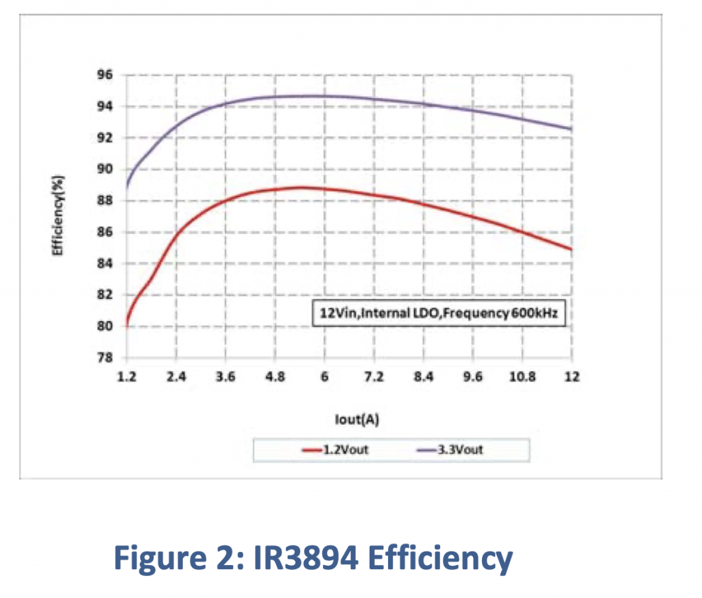
I have been working on a power supply for a new IoT device that I am building you can read about it here.  This power supply uses an Infineon IR3894 DC buck converter to turn 20V from a Type-C wall wart into a usable 5V for my system.  In the IRDC3894 data sheet there is a graph of efficiency versus load current that I would like to duplicate with real measurements.

In order to make this graph you need to:

  1. Turn on the Keithley 2280-30-1 power supply (that is simulating the Type-C power supply)
  2. Set the Keithley 2380-500-15 load to +1.2A (starting at 0)
  3. Read the input voltage and current
  4. Read the output voltage and current
  5. Loop back to (2) until you get to 12A
  6. Calculate the input and output power at each of the point
  7. Plot the data

Obviously this could all be done by hand… but I know that my Power supply and DC load are both programmable over “GPIB”.  I also know that theoretically I could get National Instruments Labview and it would probably know how to do something like that.  BUT… what I really wanted was to write code in Python.

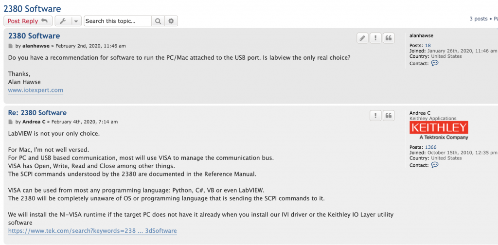
So I posted on forum.tek.com and their excellent Apps engineer “Andrea C.” replied:

I have another (future) article where I will write extensively about the bewildering jungle of Test Automation.  But for today Ill say that VISA stands for Virtual Instrument Software Architecture which is basically a standard way to talk to Lab Instruments.  And, NI-VISA is the National Instrument implementation of VISA.  But wait, a quick google search lead me to the Open Source project PyVISA.  So, I’ll start there.

There will also be a future in-depth discussion of PyVisa, but this is the first step.

PyVISA

For this example, I’ll show you the simple steps of turning on the power supply and printing out the current, voltage and calculated power as retrieved from the power supply.

I always like to use a virtual environment for working with Python on my MacBook (or any computer for that matter).  So, I start by creating the virtual environment.  Then I run the PIP installer to install PyVisa (and all of its requirements).

The specific commands are:

Command Comment
python3 -m venv venv Create a Python3 virtual environment
source venv/bin/activate Turn on the virtual environment
pip install pyusb Install the Python usb interface (so that PyVISA can search for devices on the USB bus)
pip install pyvisa Install the PyVisa environment
pip install pyvisa-py Install the low level python drivers for PyVisa to use to talk to the bus

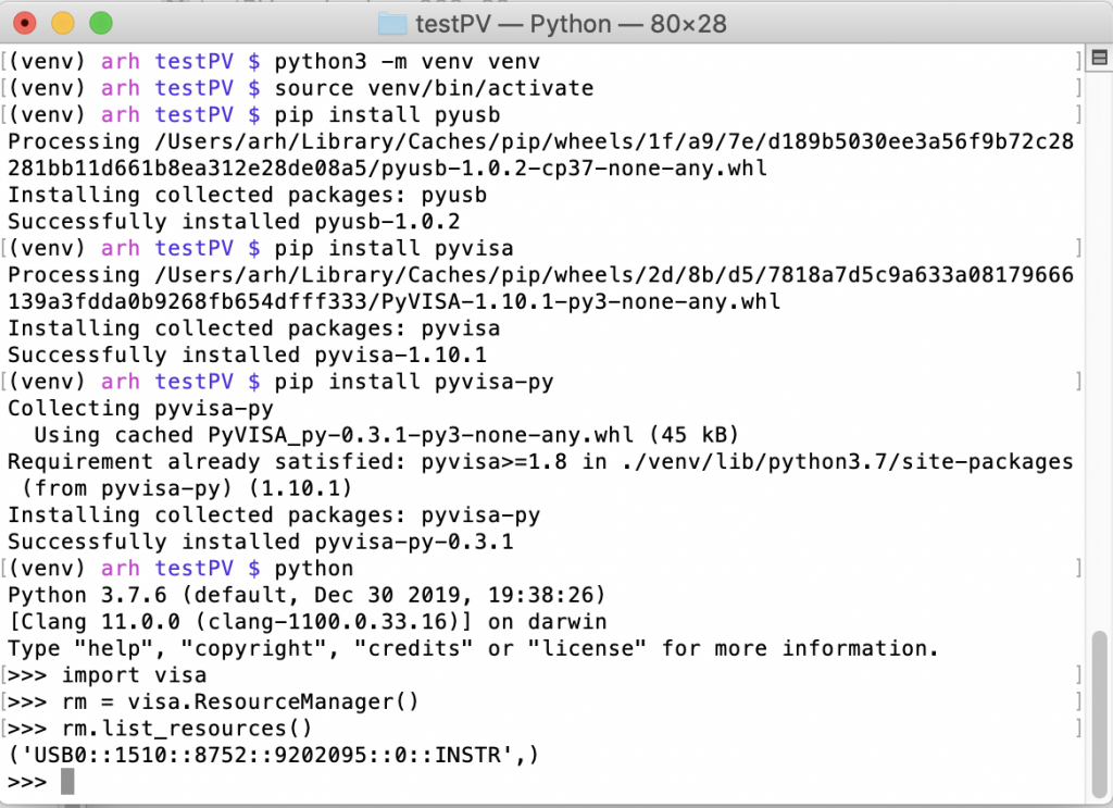
Then I tested the installation by running

Command Comment
python Startup an interactive Python environment
import visa Load the PyVISA module
rm = visa.ResourceManager() Attach to the interface
rm.list_resources() Get a list of all VISA devices attached to the interface

Here is what the screen looks like:

SCPI & Keithley 2230-30-1

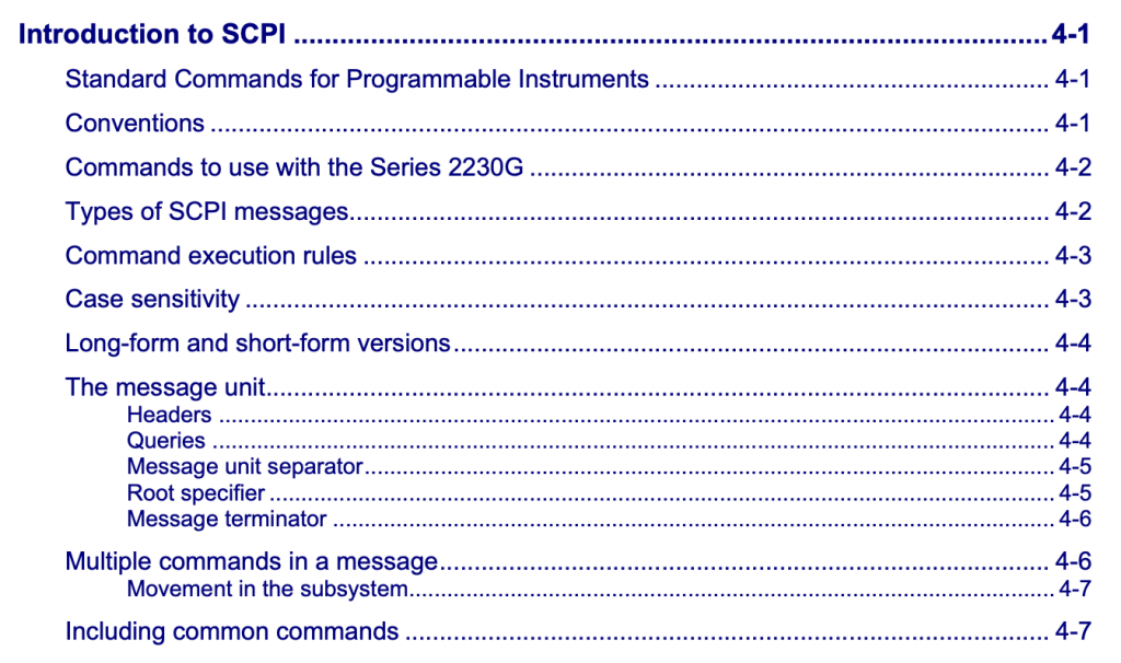
OK, we have a working Python environment that can talk to the Power Supply.  Now what? In the unbelievable chaos of talking to Test Instruments, the vendors got together and agreed to a “Standard Commands for Programmable Instruments” also called SCPI.  In order to learn about SCPI (in the context of this power supply) you can read Chapter 4 of the Keithley Power Supply user manual.  This chapter describes how commands work etc.

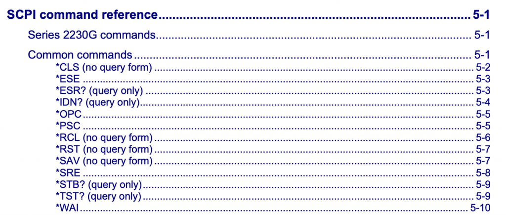
After the general section there is an entire chapter (5) that discusses the specific commands for this instrument.

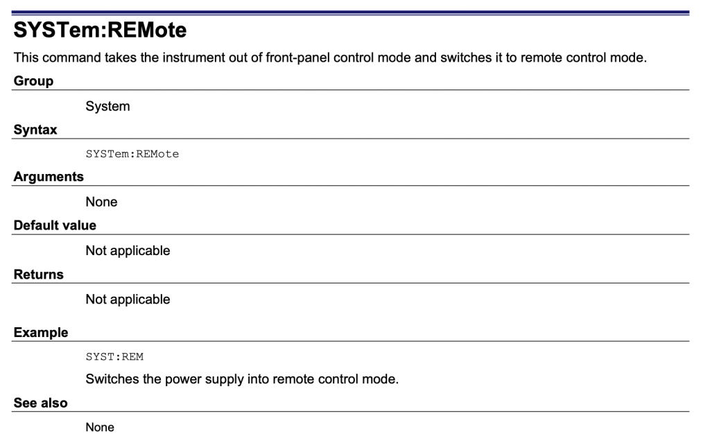
And if you look down into the document you will find a description of each of the commands.  For instance if you issue the command “SYS:REM” it will let you take control of the instrument.

Run the Test

Now that we know everything is working, I write a Python program to do the needful.

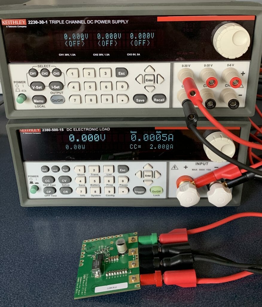
When you start the program the power supply is off and the load is set to 2A (but has no power being applied)

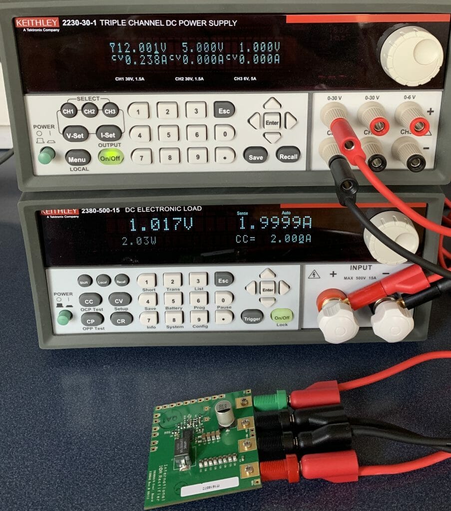
When you run the program it turns on the power supply and grabs control of device.  The little symbol next to the 12 says that the device is being control via USB.

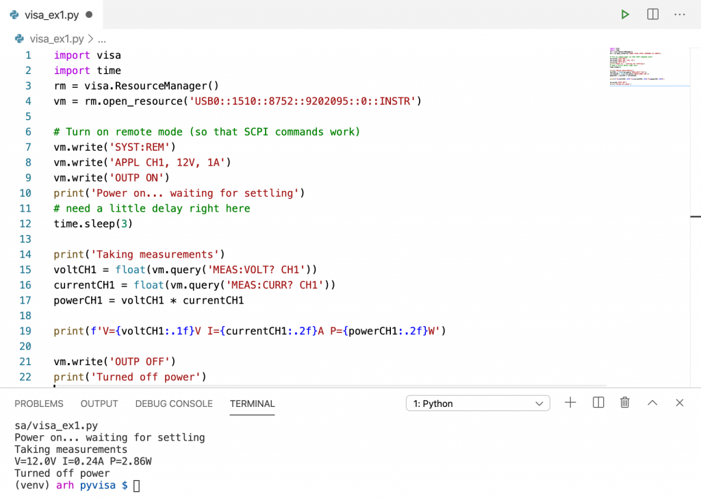
Finally here is the source code:

import visa
import time
rm = visa.ResourceManager()
vm = rm.open_resource('USB0::1510::8752::9202095::0::INSTR')

# Turn on remote mode (so that SCPI commands work)
vm.write('SYST:REM')
vm.write('APPL CH1, 12V, 1A')
vm.write('OUTP ON')
print('Power on... waiting for settling')
# need a little delay right here
time.sleep(3)

print('Taking measurements')
voltCH1 = float(vm.query('MEAS:VOLT? CH1'))
currentCH1 = float(vm.query('MEAS:CURR? CH1'))
powerCH1 = voltCH1 * currentCH1

print(f'V={voltCH1:.1f}V I={currentCH1:.2f}A P={powerCH1:.2f}W')

vm.write('OUTP OFF')
print('Turned off power')
 

Keithley 2380-500-15 Programmable Load Remote Sensing

Summary

In this article I will show you how to install and use the remote sensing inputs for the Keithley 238-500-15 Programmable Load.

The Problem

In a previous article I talked about a power supply that I was working on.  In that design, I will be taking 20V@3A from a USB Type-C power supply and turning it into 5V@12A for use to drive a PSoC and a bunch of LEDs.  For testing the setup, I use a Keithley 2380-500-15 Programmable Load that I got from Mouser.  The device is really cool as it can be programmed to provide constant current, constant resistance, constant power or constant voltage.  For this test, I am using the 2380-500-15 as constant current load to pull current out of the Infineon IRDC3894 development board which produces 1.2v@12A.

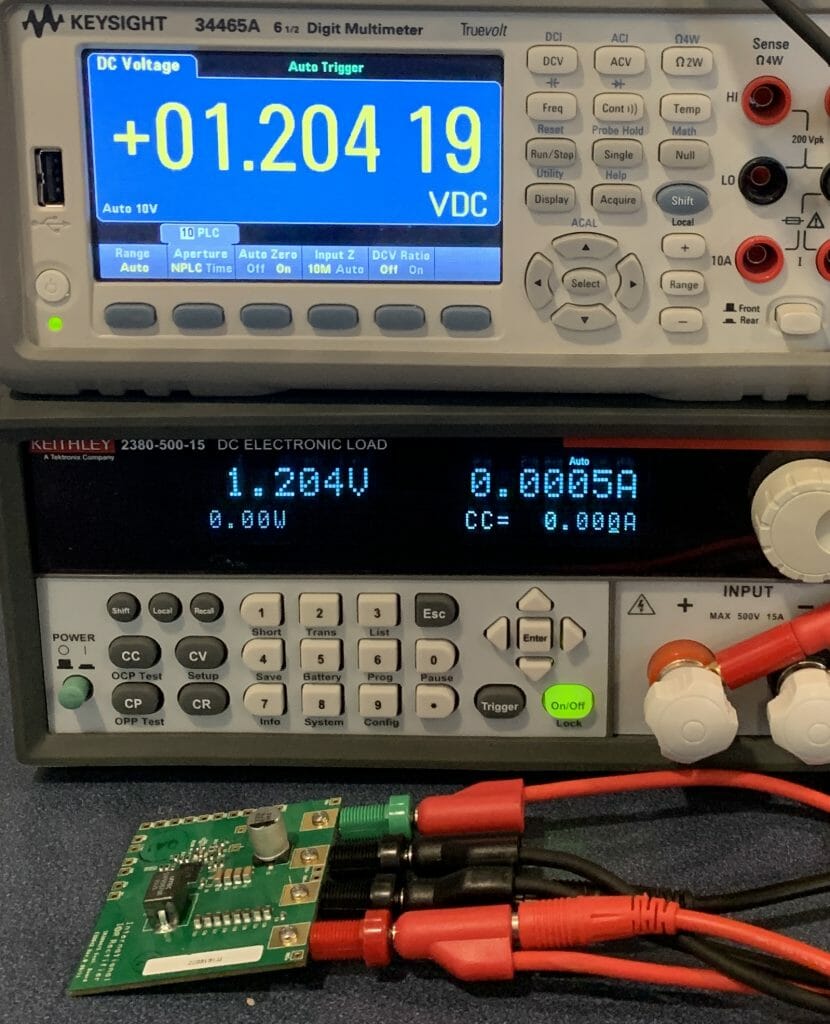
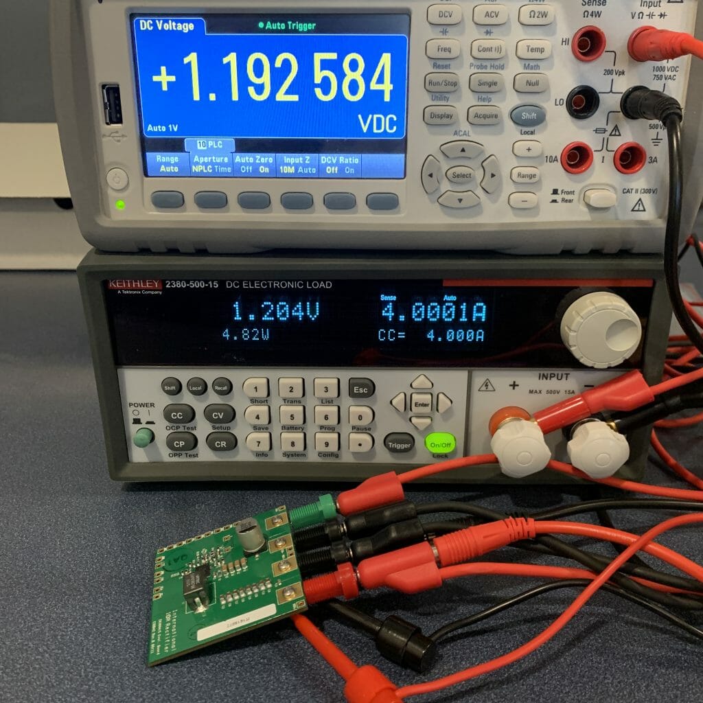
In my first setup I got this result:  The board is generating 1.2V (which you can see on the top DMM).  And the 2380-500-15 is showing 1.204V.  The same, thats good.

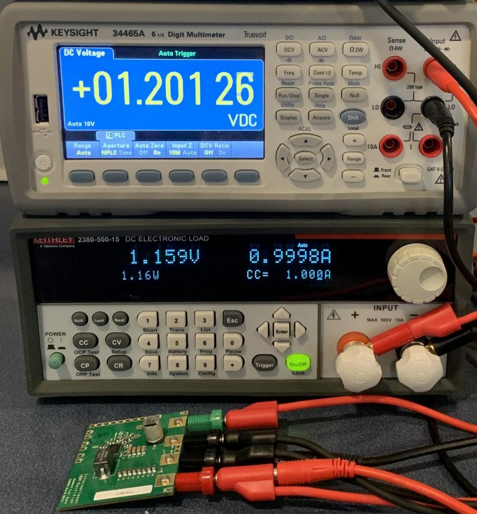
But, when I turn on the current to 1A you can see that the 2380-500-15 is showing 1.15V.  What happened?  Is the power supply drooping?

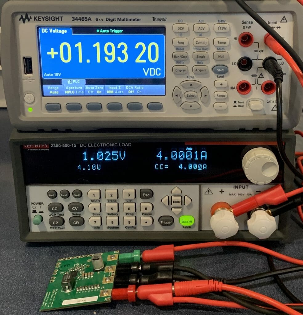
And it gets worse at 4A

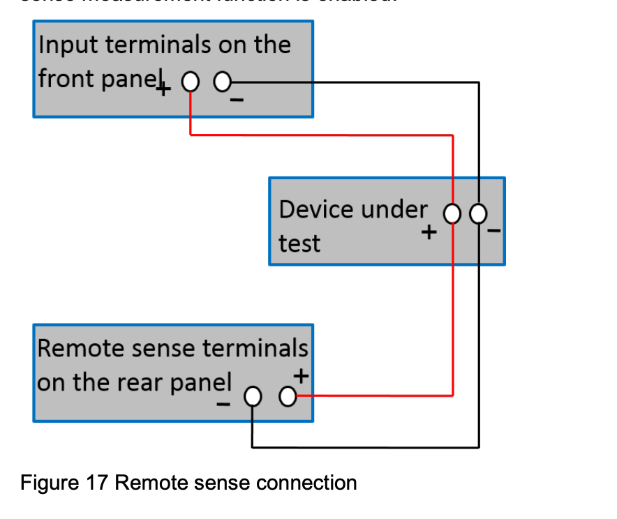
So, I posted on the Tek Forum, and the excellent Tek engineer Andrea C. gave me an answer and posted a nice picture.  The problem is that my test wire to the 2380-500-15 has resistance and the voltage is dropping through the test wire.  You mean test-wires have resistance 🙂  Here is the picture that she posted.

The Solution

So, what is the answer to this problem?  Remote sensing which will display the voltage at the source instead of at the end of the wire.  In the world this method is more commonly called “4 terminal sensing” or “Kelvin Sensing”

The 2380 is capable of using this method.  And it is described (poorly) on page 52 of the user guide.  Here is the picture:
To make this work you need to do two things

  1. Attach two wires on the back panel sensing connection
  2. Switch the load into remote sensing mode.

Back Panel

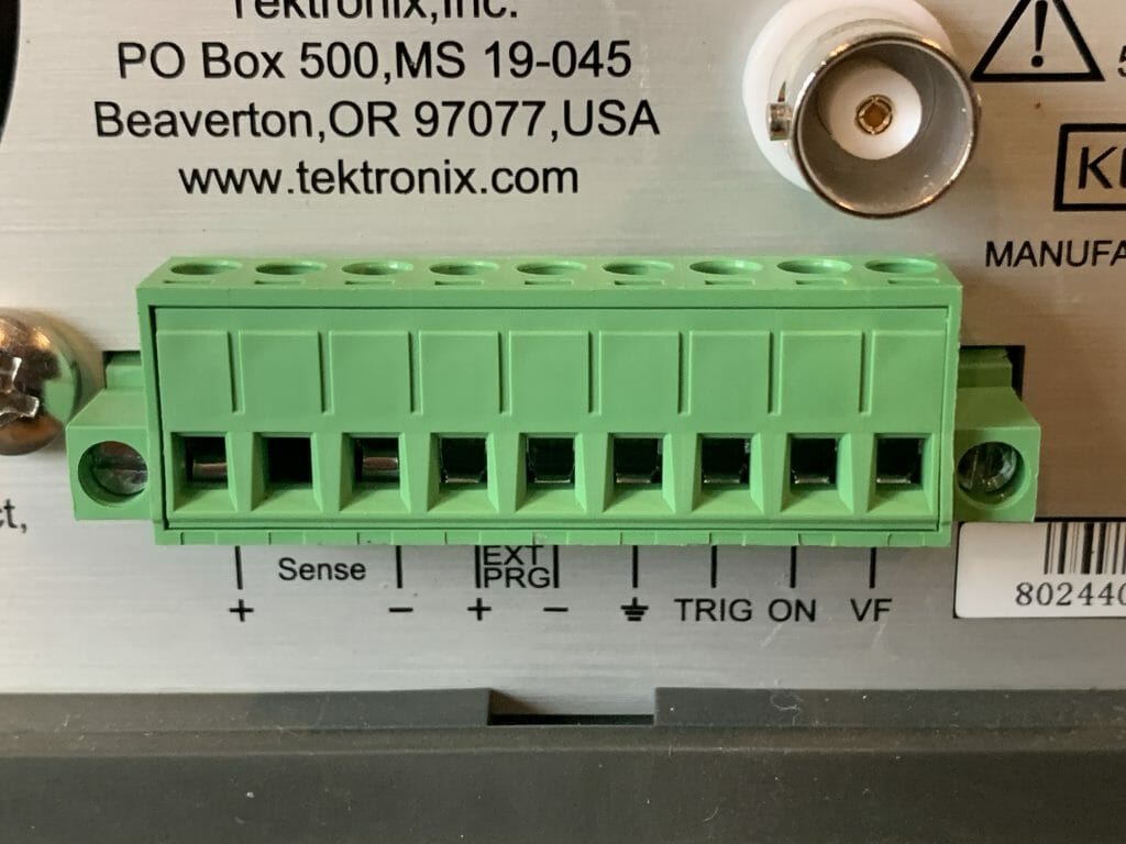
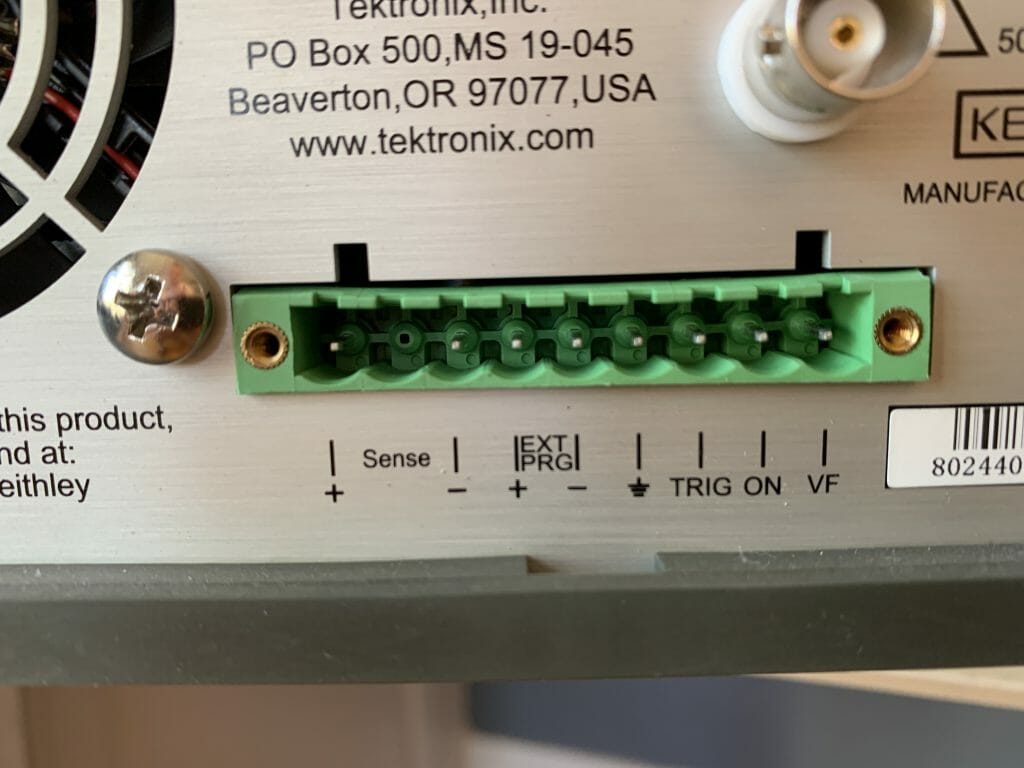
When you look at the back panel you see this crazy terminal block.  The first thing you notice is that some of the screw terminals are blocked by the BNC connector.  And the angle for putting a screw driver isn’t great.

But, if you loosen the two flat head screws on the far left and right of the green connector, you will be able to pull it out.  It has a little bit of “snap” so you need to pull on it a bit (just with your fingers so you don’t break it).  You will then be able to see into the connector.

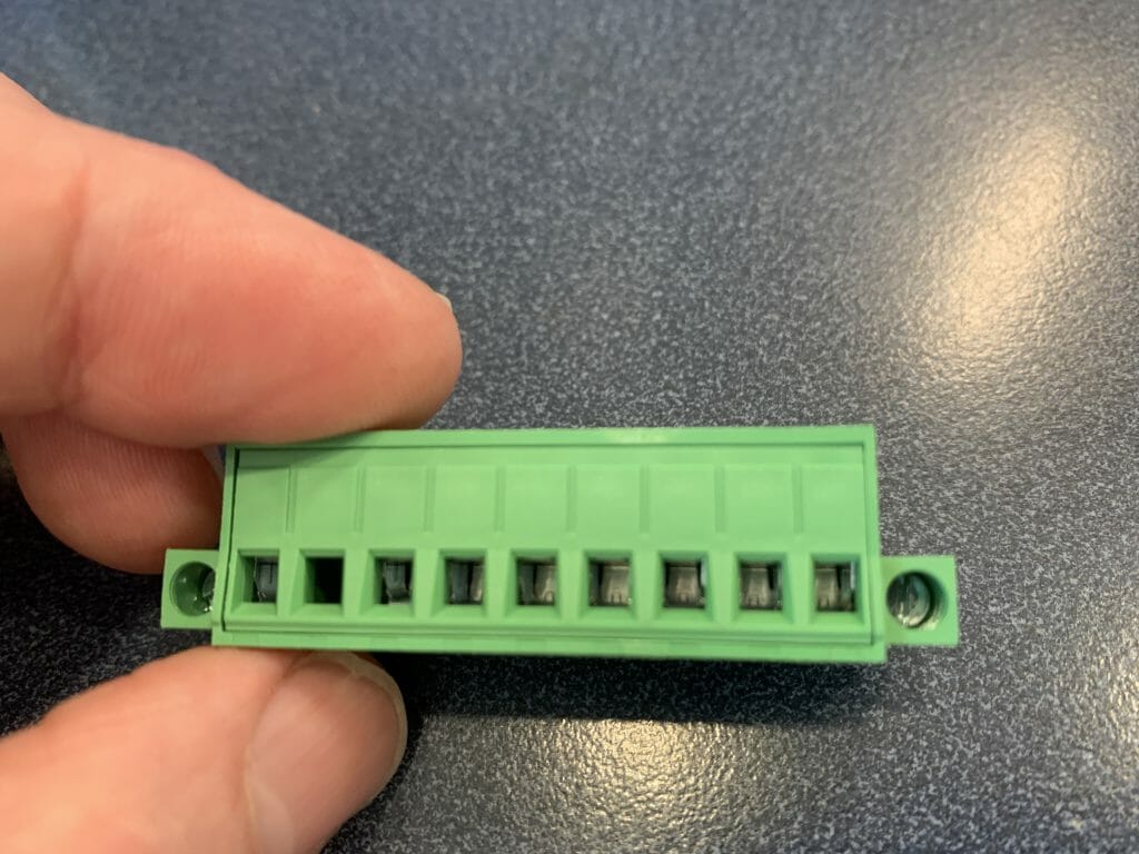
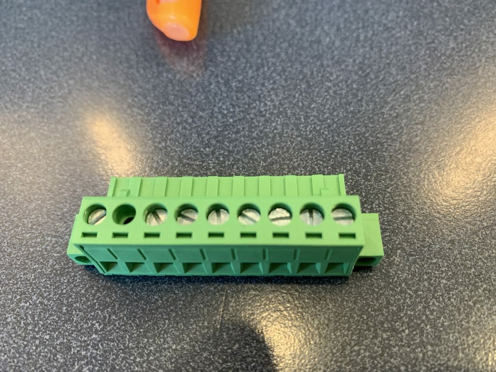
Here is what the green connector looks like once it is removed.

Notice that each of the terminals have a screw to tighten the corresponding wire.

In order to hook to the screw terminals you need a cable.  I bought this one from Mouser

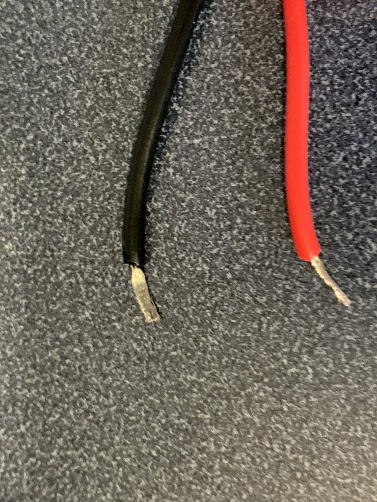
Then I clipped off the Banana plug, and tinned the ends of the wire with solder (you can see the black wire is a bit flattened because I took this picture after I unhooked the wire)

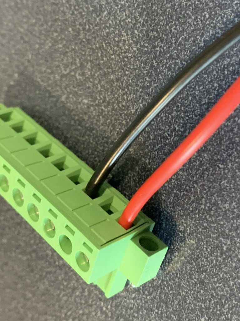
Then screwed the wires into the connector

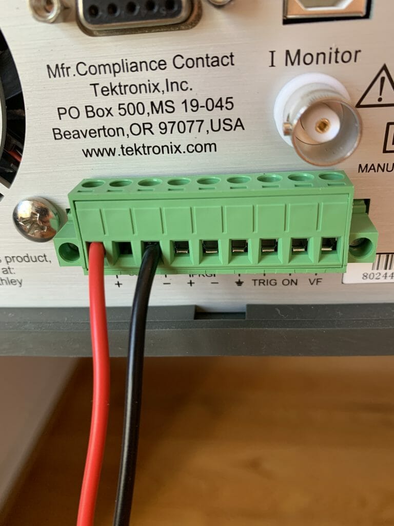
Finally screwed the connector back into the meter.

Enable Remote Sensing

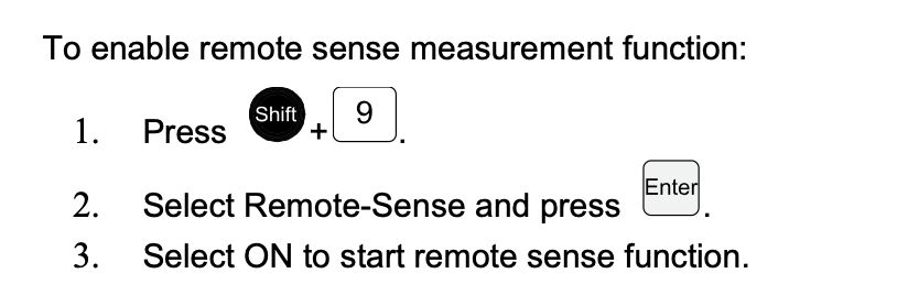
To enable remote sensing, the documentation tells you what to do:

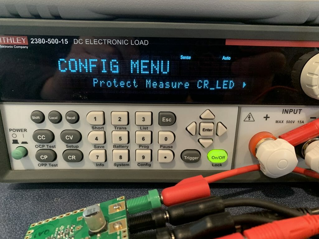
Here are pictures of the screens.  When you press Shift-9 you get this screen.  You need to press the “right arrow” to go to the next screen.

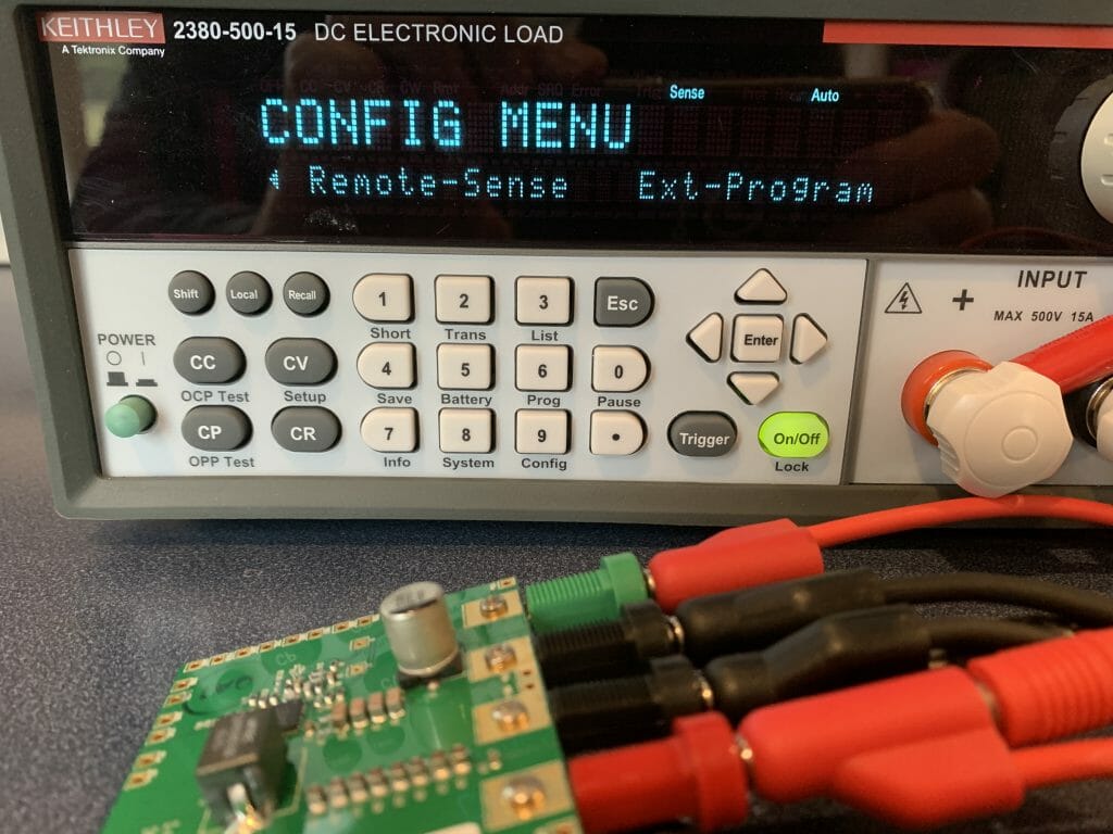
Select the “Remote-Sense” and press enter.

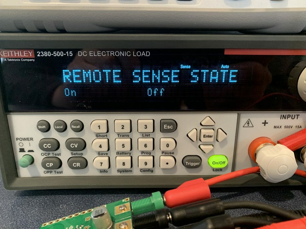
Use the left/right arrow to select “On” and press the “Enter”

Results

Now it displays “1.204V” which matches the DMM (well pretty close)

Cypress Type-C Barrel Connector Replacement + Infineon Buck DC/DC (part 1)

Summary

In this article I will walk you through the first steps of building a complete Type-C power supply that will look like this:

The Project

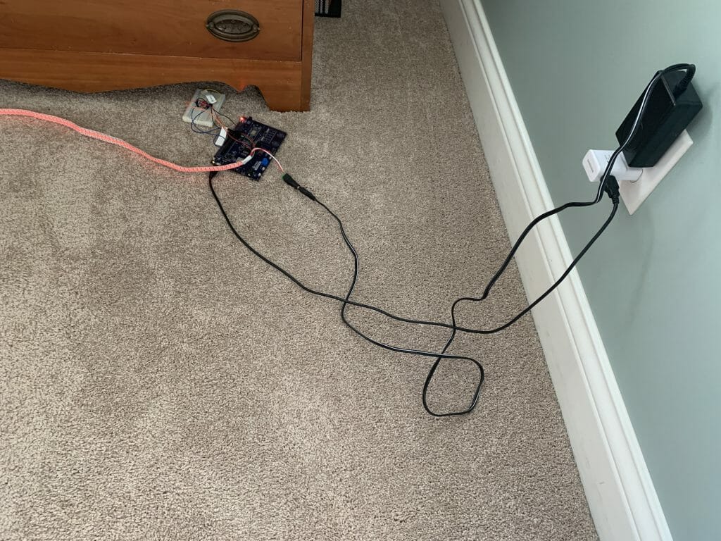
I have been working on a project that will drive several strings of WS2812 LEDs.  Specifically, a CapSense dimmable “IoT-ified” nightlight using a PSoC 6 attached to a CYW43012 attached to a string of WS2812 LEDs.   Right now, I have this thing built up with a development kit + a breadboard + 2 wall warts and it is sitting on the floor beside my bed.

When you see this picture, I’m sure that you are thinking.  “You are probably going to be sleeping on the floor beside your bed if you don’t do something better than that.”  And you would be right.  I know that I want a single PCB in a nice 3-d printed box that does all of this.  I also know that I want to use Type-C instead of a normal 12v wall wart.  When I started this I had only the vaguest ideas about how to turn Type-C into something that could drive a bunch of LEDs and a PSoC.  How much power do I need?  And at what voltages?  That seemed like the first question that needed answering.

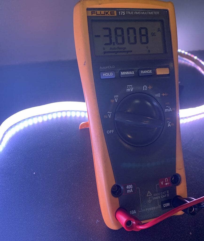
First, I put a meter on a string of 144 WS2812 LEDs.  Wow, 5V at ~4A when the LEDs are full on.  That is 20W per string… basically 30mA per WS2812.

To make a board that can drive three strings of these LEDs I am going to require 3x20w + whatever the PSoC takes.  A bunch.  But where should I get this much power?  The answer is I am going to start with a laptop Type-C charger like this one from Apple (which I have several of)

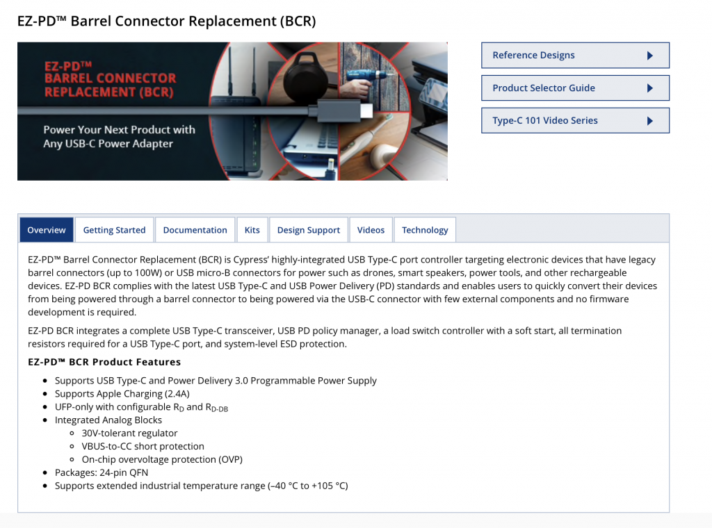
The first/next question is, how do I tell the Apple adaptor what voltage/current I want?  It turns out that Cypress is the leader in Type-C chips and we make the perfect chip for this application.  It is called the CYPD3177-24LQXQ and is known colloquially as the EZ-PD™ Barrel Connector Replacement (BCR).  This is good because that is exactly what I want to do, replace a wall wart barrel with a Type-C.

Cypress CY4533 Development Kit

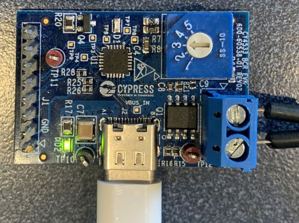
To get this going I start with the Cypress CY4533 development kit which you can see in the picture below.

This board has

  1. A place to plug in Type-C
  2. A 5 position switch to tell the EZ-PD chip to select (5, 9,12,15 or 20V)
  3. Screw terminals for the output voltage
  4. A header with an I2C connection to the EZ-PD chip
  5. A load switch to isolate the load

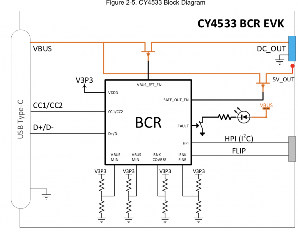
Here is a block diagram

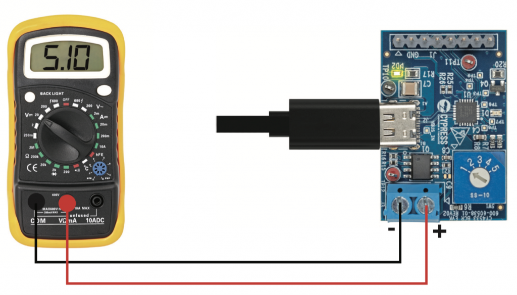
The kit quick start guide has a picture of exactly what I did next

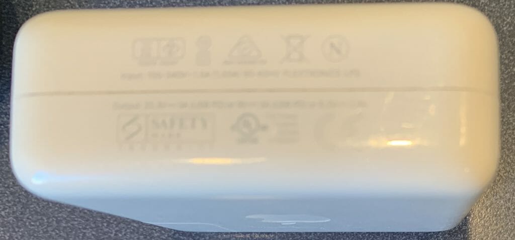
When I turned the selector, I noticed that the output from my Apple charger was (5, 9, 9, 9, 20) and wondered why.  Yet, when I measured another Type-C power supply I got (5, 9, 12, 15, and 20).  It turns out that when you read the fine print on the side of the charger it tells you the answer.  Here is a picture of the side where unfortunately you can’t read (but I used a magnifying glass)

  • 20V @ 3A = 60W
  • 9V @ 3A = 27W
  • 5V @ 2.4A = 12W

The kit guide gives you the answer as to why 5,9,9,9,20:

Infineon

OK.  All that is great, but how do I power my board where I need 5V@12A + 3.6V + 3.3V + 1.8V, this is where Infineon comes into the picture.  Actually, to be completely clear, Infineon came into the picture starting mid-last year when they offered to pay $10B-ish for Cypress.

Infineon makes a line of Buck regulators which are perfect for solving the first part of my problem because

  1. They take high-ish voltage inputs (up to 21V)
  2. They can supply high-ish currents at the right voltage (up to 35A)

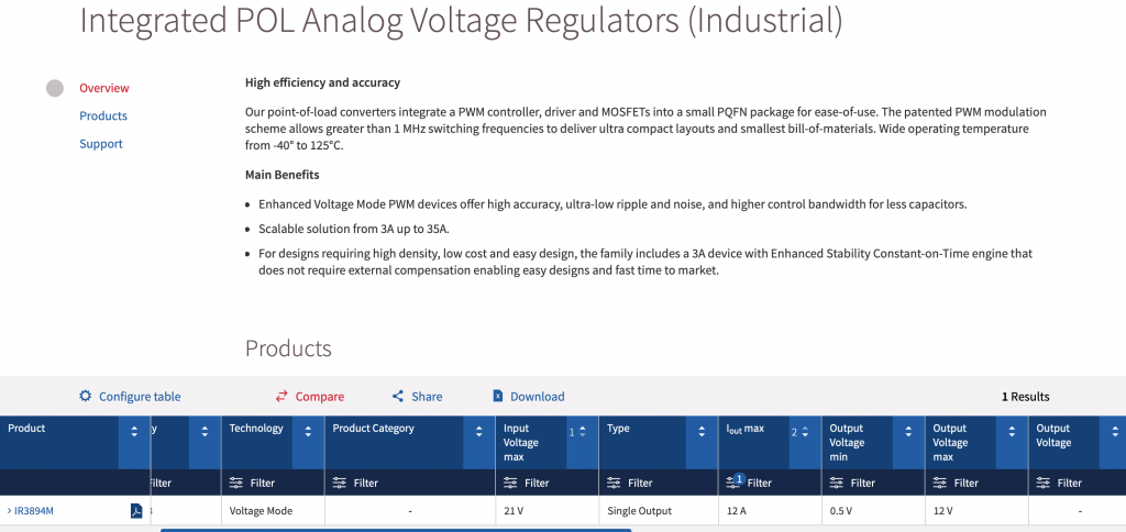
These regulators are called the “SupIRBuck” and are part of the “Integrated POL Analog Voltage Regulators (Industrial)

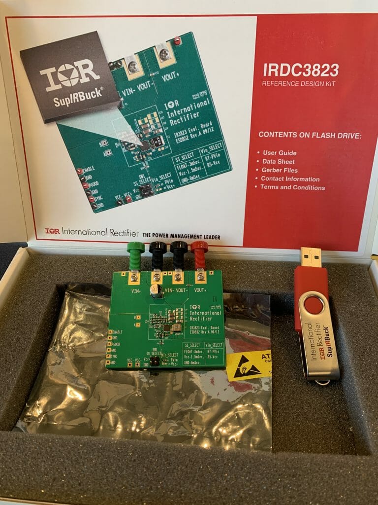
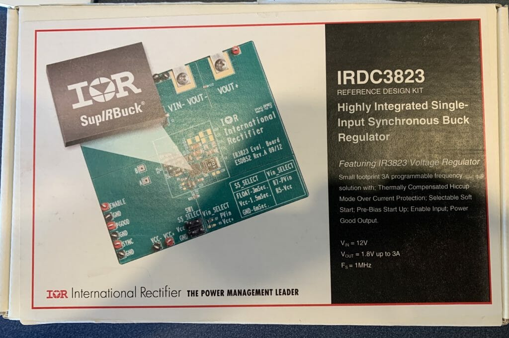
So, I ordered a development kit… unfortunately I  choose the wrong one, IRDC3823 which is 12V @ 3A.  However, it was close enough for me to try out.

The board came in a box with the kit and a USB stick.

The USB Stick had the Kit Guide, Datasheet, and Gerber Files. That was nice of them.

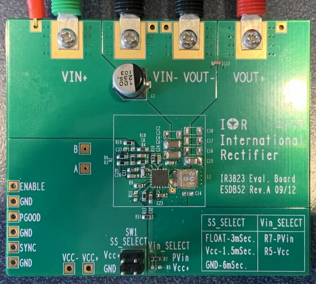
The kit it actually very simple.  It has a place to plug in your input supply (the two terminals on the left).  And it has a place to plug in the output.

The board also has a place to configure the startup time of the Buck (the little four position jumper).  When I connected the EZ-PD BCR kit to the IR3823 Eval Board, look what I got.  1.2V.  Great.

This is cool and all of that… but I have a bunch of questions that need answering

  1. How do I get 5V out (instead of 1.2V)
  2. Why does the the kit guide say a maximum of 13V on the input?
  3. How do I configure the PGOOD signal to be compatible with the PSoC
  4. How do I measure the efficiency?
  5. What is all this stuff about switching frequency and what is the right number?
  6. What should I choose for SS_Select and why?
  7. What is an “external VCC about?
  8. How do I get 5A (instead of 900mA)?
  9. How do I talk to the EZ-PD chip via I2C?

All of these questions and more are deferred to future articles.