Summary
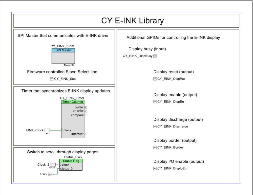
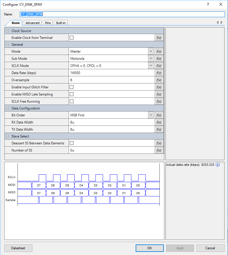
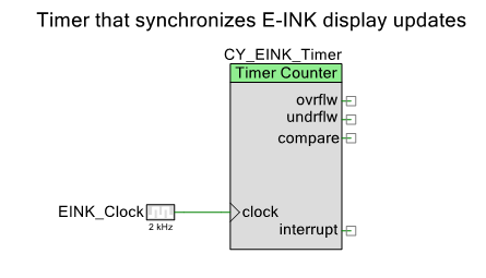
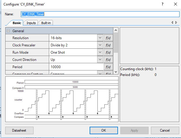
In the first article of this series I talked about how to make the CY8CKIT-028-EPD EINK Shield work with PSoC 6 and Modus Toolbox 1.1. In the second article I improved the interface and talked about the PSoC 6 clocking system. In this article I want to address the timing system in the EINK firmware. You might recall that I used one of the Timer-Counter-Pulse-Width-Modulator blocks a.k.a the TCPWM inside of the PSoC 6 as a Timer for updating the EINK Screen. Using this timer was a bit of a waste as the CM4 already has a timer built into the device called the SysTick timer. Moreover, the SysTick timer is connected to the FreeRTOS timing system which provides you APIs to talk to it. For this article I will talk about:
- ARM SysTick
- Cypress PDL and SysTick
- FreeRTOS and SysTick
- Make a new project & copy the files
- Use the FreeRTOS timing system to measure the speed increase of the updated SPI
- Remove the hardware timer & replace with the RTOS timer.
ARM SysTick
The ARM Cortex-M MCUs have an option to include a 24-bit timer called SysTick. As best I can tell, every MCU maker always chooses to have the SysTick option built in. Certainly the PSoC 4 and PSoC 6 family all have it built in. But how do you talk to it? Well, my buddy Reinhard Keil decided that it was silly for everyone to create a different method for interacting with standard ARM peripherals so he created the Cortex Microcontroller Software Interface Standard (CMSIS)

CMSIS defines two things that you need to do to make the SysTick timer work. First, you need to create a function called EXACTLY “SysTick_Handler”. This function gets loaded into the vector table of your program as the interrupt handler for the SysTick interrupt. As such the function prototype is “void SysTick_Handler(void)”. The second thing that you need to do is initialize how often the timer should be called. You do this with the CMSIS call:
SysTick_Config(SystemCoreClock/1000);
It is interesting to note that the symbol SystemCoreClock is also defined by CMSIS as the frequency of the clock. So the above call would setup the SysTick to be called every 1Ms (that is why there is a divide by 1000).
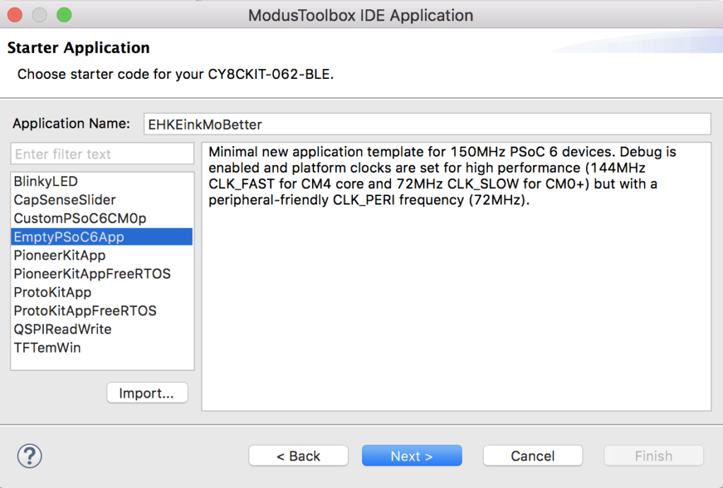
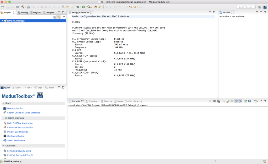
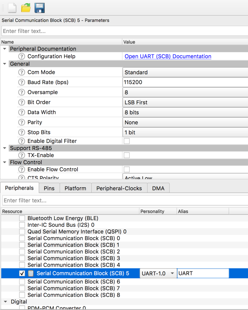
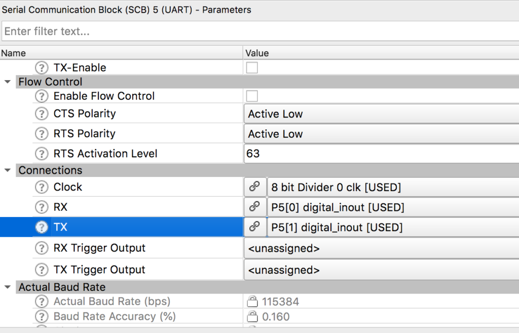
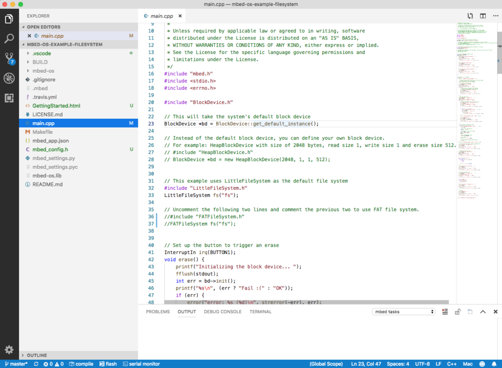
Here is an example I created starting with the BlinkyLED example project. After I created the project, I added the kitprog uart (which is SCB5) and I added the Retarget I/O middleware.
#include "cy_pdl.h"
#include "cycfg.h"
#include <stdio.h>

volatile uint32_t count;

void SysTick_Handler(void)
{
	count += 1;
}
cy_stc_scb_uart_context_t kitprog_context;

int main(void)
{
	Cy_SCB_UART_Init(kitprog_HW,&kitprog_config,&kitprog_context);
	Cy_SCB_UART_Enable(kitprog_HW);
    /* Set up internal routing, pins, and clock-to-peripheral connections */
    init_cycfg_all();

    SysTick_Config(SystemCoreClock/1000);

    /* enable interrupts */
    __enable_irq();

    for (;;)
    {
    		printf("Test count=%d\n",(int)count);
        Cy_GPIO_Inv(LED_RED_PORT, LED_RED_PIN); /* toggle the pin */
        Cy_SysLib_Delay(1000/*msec*/);
    }
}
Don’t forget to setup the standard i/o by modifying stdio_user.h
#include "cycfg.h"
/* Must remain uncommented to use this utility */
#define IO_STDOUT_ENABLE
#define IO_STDIN_ENABLE
#define IO_STDOUT_UART      kitprog_HW
#define IO_STDIN_UART       kitprog_HW
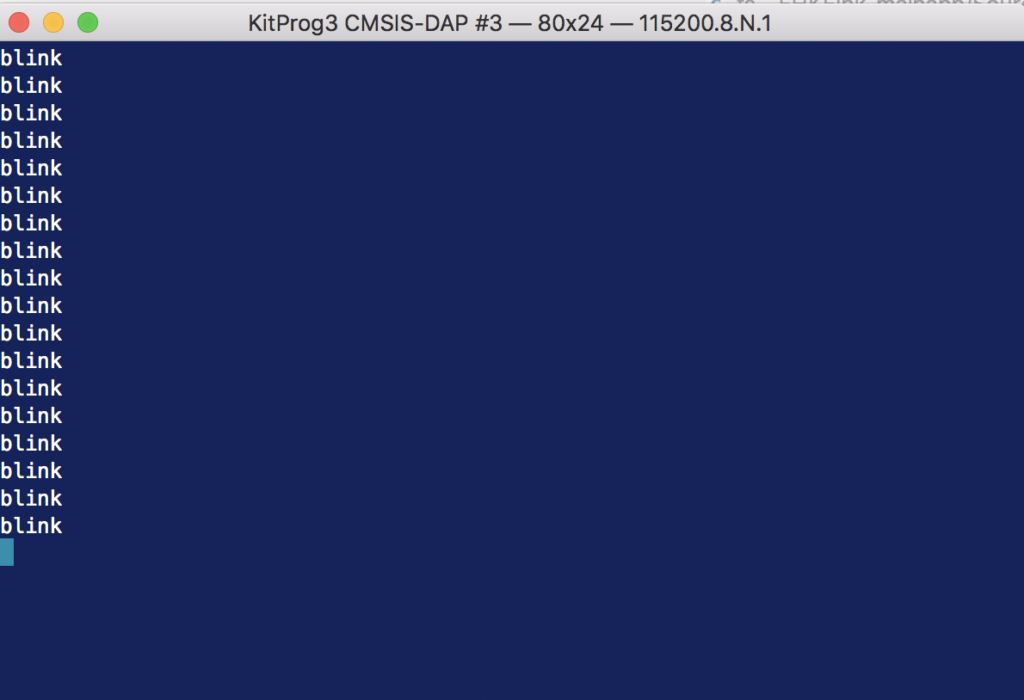
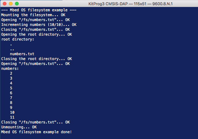
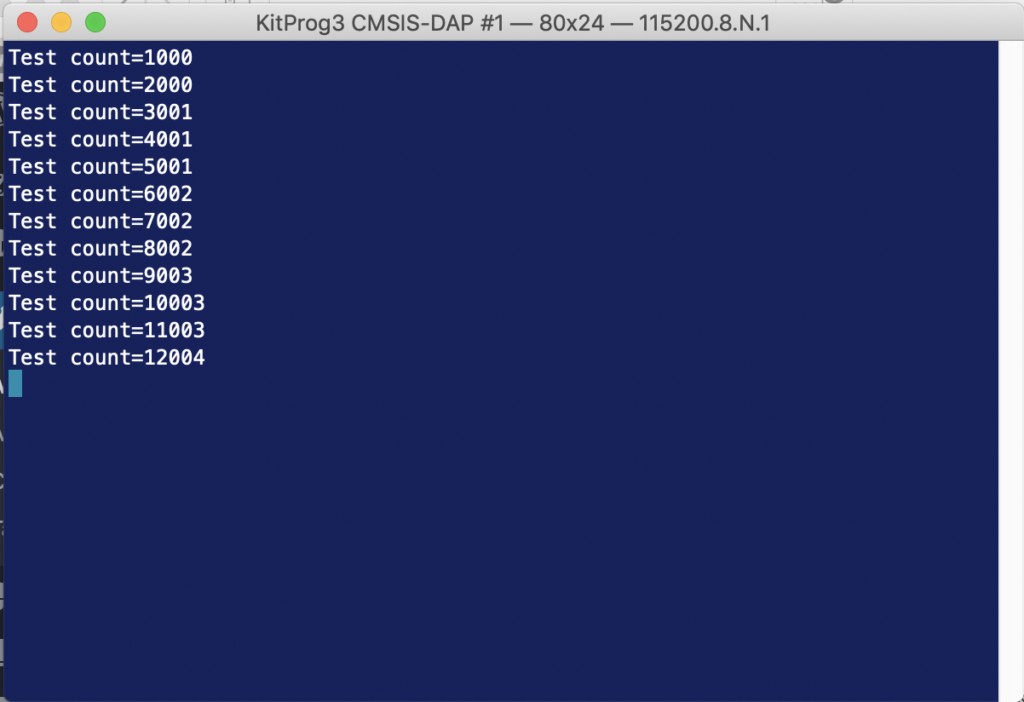
When you run the program above you should get something like this:
One interesting question is HOW does the function SysTick_Handler get into the vector table? Well if you run an eclipse search (type ctrl-h)
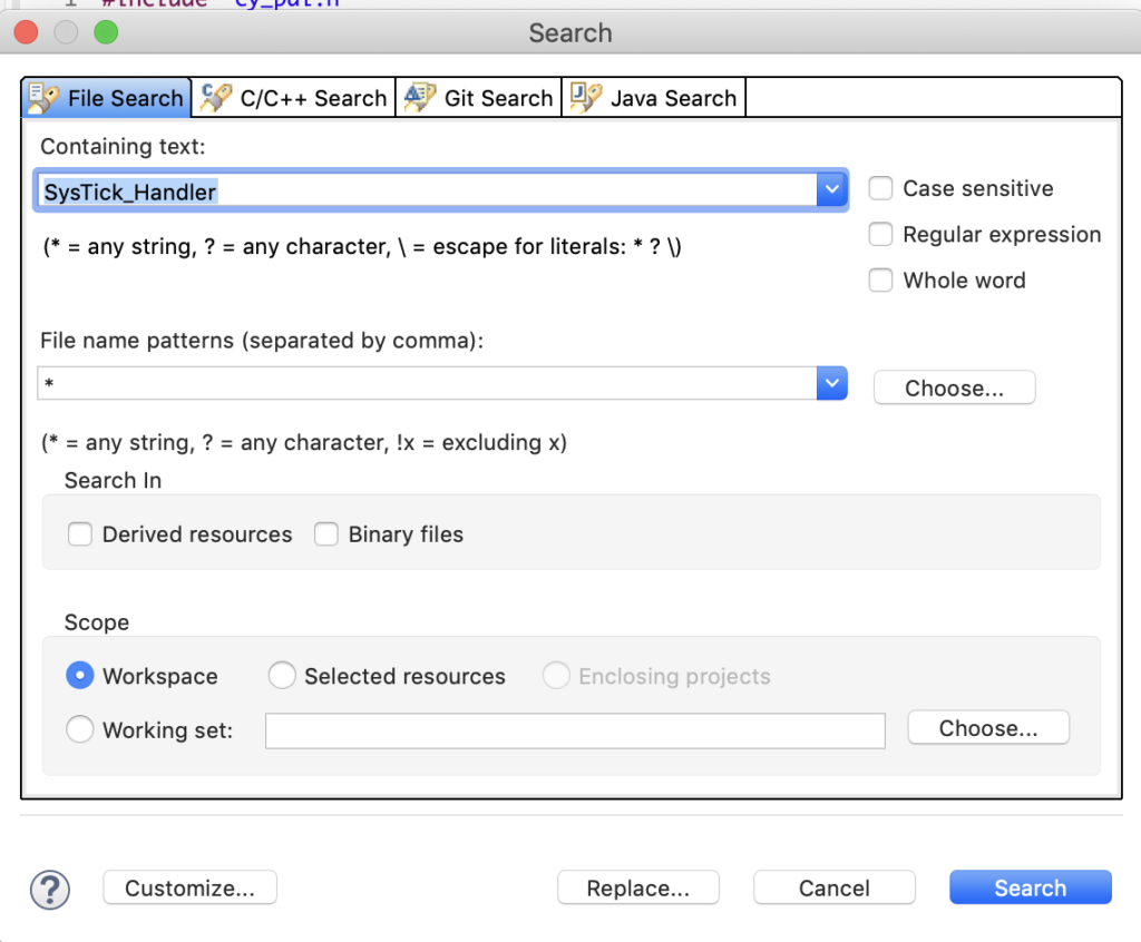
You will find it in an assembly language file called “startup_psoc6_01_cm4.s”
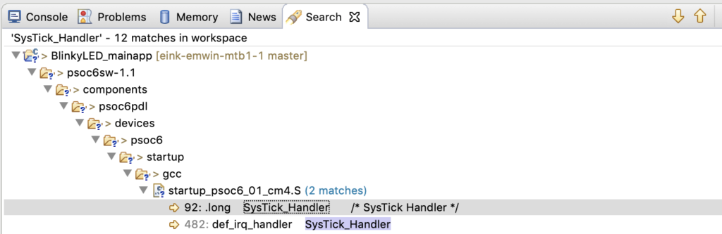
Double click on the file and you can see the Vector table.
__Vectors:
    .long    __StackTop            /* Top of Stack */
    .long    Reset_Handler         /* Reset Handler */
    .long    CY_NMI_HANLDER_ADDR   /* NMI Handler */
    .long    HardFault_Handler     /* Hard Fault Handler */
    .long    MemManage_Handler     /* MPU Fault Handler */
    .long    BusFault_Handler      /* Bus Fault Handler */
    .long    UsageFault_Handler    /* Usage Fault Handler */
    .long    0                     /* Reserved */
    .long    0                     /* Reserved */
    .long    0                     /* Reserved */
    .long    0                     /* Reserved */
    .long    SVC_Handler           /* SVCall Handler */
    .long    DebugMon_Handler      /* Debug Monitor Handler */
    .long    0                     /* Reserved */
    .long    PendSV_Handler        /* PendSV Handler */
    .long    SysTick_Handler       /* SysTick Handler */
But how do the _Vectors get into the right place? Well? run the search again and you will find that the linker script (which Cypress created) for your project has the definition.
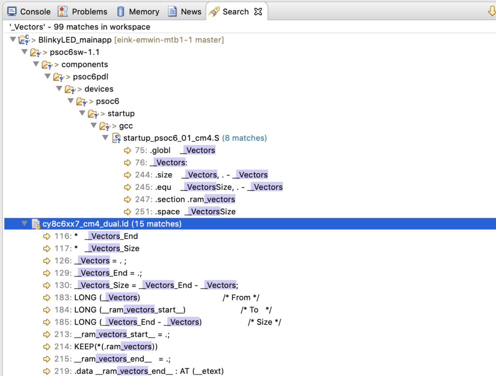
When you look in the linker script you can see that it is installed at the top of the flash
    {
        . = ALIGN(4);
        __Vectors = . ;
        KEEP(*(.vectors))
        . = ALIGN(4);
        __Vectors_End = .;
        __Vectors_Size = __Vectors_End - __Vectors;
        __end__ = .;

        . = ALIGN(4);
        *(.text*)

        KEEP(*(.init))
        KEEP(*(.fini))

        /* .ctors */
        *crtbegin.o(.ctors)
        *crtbegin?.o(.ctors)
        *(EXCLUDE_FILE(*crtend?.o *crtend.o) .ctors)
        *(SORT(.ctors.*))
        *(.ctors)

        /* .dtors */
        *crtbegin.o(.dtors)
        *crtbegin?.o(.dtors)
        *(EXCLUDE_FILE(*crtend?.o *crtend.o) .dtors)
        *(SORT(.dtors.*))
        *(.dtors)

        /* Read-only code (constants). */
        *(.rodata .rodata.* .constdata .constdata.* .conststring .conststring.*)

        KEEP(*(.eh_frame*))
    } > flash
And the CM4 flash is defined to start at 0x100002000
MEMORY
{
    /* The ram and flash regions control RAM and flash memory allocation for the CM4 core.
     * You can change the memory allocation by editing the 'ram' and 'flash' regions.
     * Note that 2 KB of RAM (at the end of the RAM section) are reserved for system use.
     * Using this memory region for other purposes will lead to unexpected behavior.
     * Your changes must be aligned with the corresponding memory regions for CM0+ core in 'xx_cm0plus.ld',
     * where 'xx' is the device group; for example, 'cy8c6xx7_cm0plus.ld'.
     */
    ram               (rwx)   : ORIGIN = 0x08002000, LENGTH = 0x45800
    flash             (rx)    : ORIGIN = 0x10002000, LENGTH = 0xFE000

    /* This is a 32K flash region used for EEPROM emulation. This region can also be used as the general purpose flash.
     * You can assign sections to this memory region for only one of the cores.
     * Note some middleware (e.g. BLE, Emulated EEPROM) can place their data into this memory region.
     * Therefore, repurposing this memory region will prevent such middleware from operation.
     */
    em_eeprom         (rx)    : ORIGIN = 0x14000000, LENGTH = 0x8000       /*  32 KB */

    /* The following regions define device specific memory regions and must not be changed. */
    sflash_user_data  (rx)    : ORIGIN = 0x16000800, LENGTH = 0x800        /* Supervisory flash: User data */
    sflash_nar        (rx)    : ORIGIN = 0x16001A00, LENGTH = 0x200        /* Supervisory flash: Normal Access Restrictions (NAR) */
    sflash_public_key (rx)    : ORIGIN = 0x16005A00, LENGTH = 0xC00        /* Supervisory flash: Public Key */
    sflash_toc_2      (rx)    : ORIGIN = 0x16007C00, LENGTH = 0x200        /* Supervisory flash: Table of Content # 2 */
    sflash_rtoc_2     (rx)    : ORIGIN = 0x16007E00, LENGTH = 0x200        /* Supervisory flash: Table of Content # 2 Copy */
    xip               (rx)    : ORIGIN = 0x18000000, LENGTH = 0x8000000    /* 128 MB */
    efuse             (r)     : ORIGIN = 0x90700000, LENGTH = 0x100000     /*   1 MB */
}
And when you look at the linker MAP file which is in your project Debug/BlinkyLED_mainapp.map you will see that the vectors end up in the right place.
.text           0x0000000010002000     0x5de4
                0x0000000010002000                . = ALIGN (0x4)
                0x0000000010002000                __Vectors = .
Cypress SysTick
Now if you happen to be reading the PDL documentation on Saturday afternoon you might notice that there is a section of the documentation called “SysTick”. And when you click it you will find this:
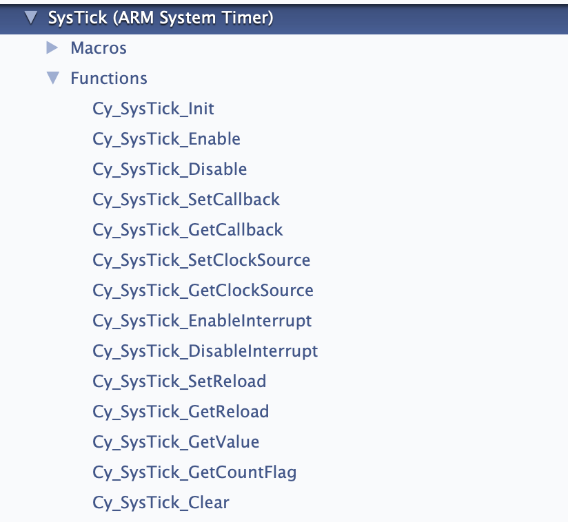
And you might ask yourself “What the hell.. those aren’t CMSIS functions?” Well in typical Cypress fashion we created an extension to SystTick. It does two basic things
- Lets you pick different clock sources for the SysTick timer
- Lets you setup multiple callbacks to make it easier to trigger multiple functions in your system
For this example I modified the previous project by commenting out the CMSIS calls. And I use the Cy_SysTick calls.
#include "cy_pdl.h"
#include "cycfg.h"
#include <stdio.h>

volatile uint32_t count;
cy_stc_scb_uart_context_t kitprog_context;

#if 0
void SysTick_Handler(void)
{
	count += 1;
}
#endif

void MyHander(void)
{
	count += 1;
}

int main(void)
{
	Cy_SCB_UART_Init(kitprog_HW,&kitprog_config,&kitprog_context);
	Cy_SCB_UART_Enable(kitprog_HW);
    /* Set up internal routing, pins, and clock-to-peripheral connections */
    init_cycfg_all();

    Cy_SysTick_Init ( CY_SYSTICK_CLOCK_SOURCE_CLK_CPU, 100000000/1000); // CPU Freq divide by 1000 makes MS
    Cy_SysTick_SetCallback(0,MyHander); // Slot 0
    Cy_SysTick_Enable();

//    SysTick_Config(SystemCoreClock/1000);

    /* enable interrupts */
    __enable_irq();

    for (;;)
    {
    		printf("Test count=%d\n",(int)count);
        Cy_GPIO_Inv(LED_RED_PORT, LED_RED_PIN); /* toggle the pin */
        Cy_SysLib_Delay(1000/*msec*/);
    }
}
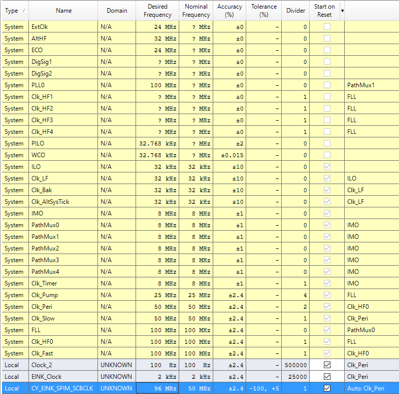
When you look at this program you might ask where I got the “100000000/1000″…. and if Hassane is reading he will ask WHY DIDN’T YOU COMMENT IT. The answer to the first question is that it is the CPU Frequency divided by 1000 to get a millisecond timer.
As to the second question… the answer is … “I just did” 🙂
There is probably some MACRO for those values… but I just don’t know what they are… and I suppose that I should go look… but…
And finally the “// slot 0” means that it uses the first of 5 slots… in other words places where you can store a callback.

FreeRTOS usage of SysTick
The FreeRTOS by default uses the SysTick timer to cause the scheduler to run. And it does this by using the CMSIS interface… well because everyone needs to do their own thing, it actually lets you define the function. Here is a clip out of FreeRTOSConfig.h where it defines the actual function name as xPortSysTickHandler.
/* Definitions that map the FreeRTOS port interrupt handlers to their CMSIS
standard names - or at least those used in the unmodified vector table. */
#define vPortSVCHandler     SVC_Handler
#define xPortPendSVHandler  PendSV_Handler
#define xPortSysTickHandler SysTick_Handler
And when you look around (using find) you will find it in the file port.c.
void xPortSysTickHandler( void )
{
	/* The SysTick runs at the lowest interrupt priority, so when this interrupt
	executes all interrupts must be unmasked.  There is therefore no need to
	save and then restore the interrupt mask value as its value is already
	known. */
	portDISABLE_INTERRUPTS();
	{
		/* Increment the RTOS tick. */
		if( xTaskIncrementTick() != pdFALSE )
		{
			/* A context switch is required.  Context switching is performed in
			the PendSV interrupt.  Pend the PendSV interrupt. */
			portNVIC_INT_CTRL_REG = portNVIC_PENDSVSET_BIT;
		}
	}
	portENABLE_INTERRUPTS();
}
And if you look in vTaskStartScheduler you will find that it calls the function vPortSetupTimerInterrupt where it sets up interrupt manually.
/*
 * Setup the systick timer to generate the tick interrupts at the required
 * frequency.
 */
__attribute__(( weak )) void vPortSetupTimerInterrupt( void )
{
	/* Calculate the constants required to configure the tick interrupt. */
	#if( configUSE_TICKLESS_IDLE == 1 )
	{
		ulTimerCountsForOneTick = ( configSYSTICK_CLOCK_HZ / configTICK_RATE_HZ );
		xMaximumPossibleSuppressedTicks = portMAX_24_BIT_NUMBER / ulTimerCountsForOneTick;
		ulStoppedTimerCompensation = portMISSED_COUNTS_FACTOR / ( configCPU_CLOCK_HZ / configSYSTICK_CLOCK_HZ );
	}
	#endif /* configUSE_TICKLESS_IDLE */

	/* Stop and clear the SysTick. */
	portNVIC_SYSTICK_CTRL_REG = 0UL;
	portNVIC_SYSTICK_CURRENT_VALUE_REG = 0UL;

	/* Configure SysTick to interrupt at the requested rate. */
	portNVIC_SYSTICK_LOAD_REG = ( configSYSTICK_CLOCK_HZ / configTICK_RATE_HZ ) - 1UL;
	portNVIC_SYSTICK_CTRL_REG = ( portNVIC_SYSTICK_CLK_BIT | portNVIC_SYSTICK_INT_BIT | portNVIC_SYSTICK_ENABLE_BIT );
}
And what is really cool is that when you look in FreeRTOSConfig.h you can see that it uses the CMSIS macro “SystemCoreClock” and that it is configured to have a 1MS callback.
#define configCPU_CLOCK_HZ                      SystemCoreClock
#define configTICK_RATE_HZ                      1000u
So, why did I look at all of that? Well simple, each time that the SysTick interrupt is called, the FreeRTOS adds 1 to a count…. which you can get access to by calling “xTaskGetTickCount”. Nice.
I think that is enough background… so let’s:
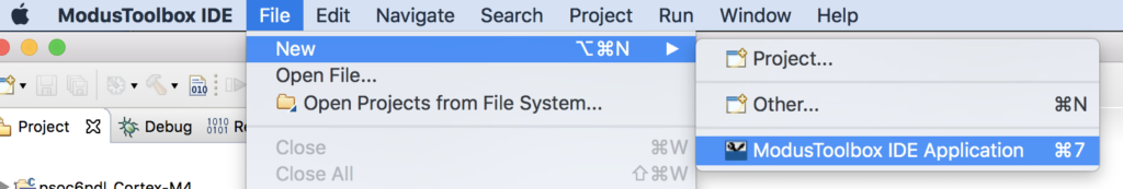
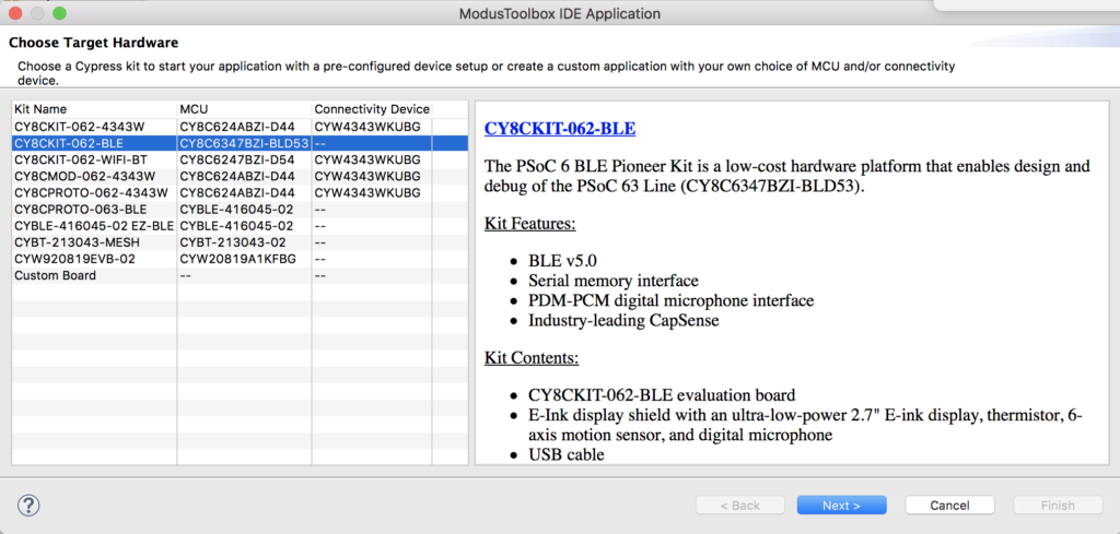
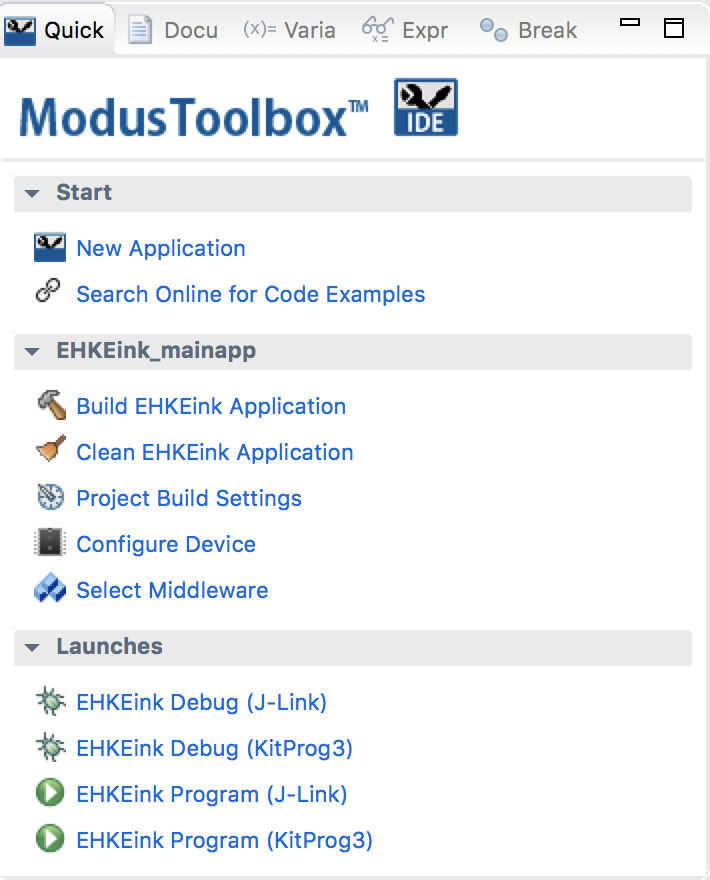
Make a New Project
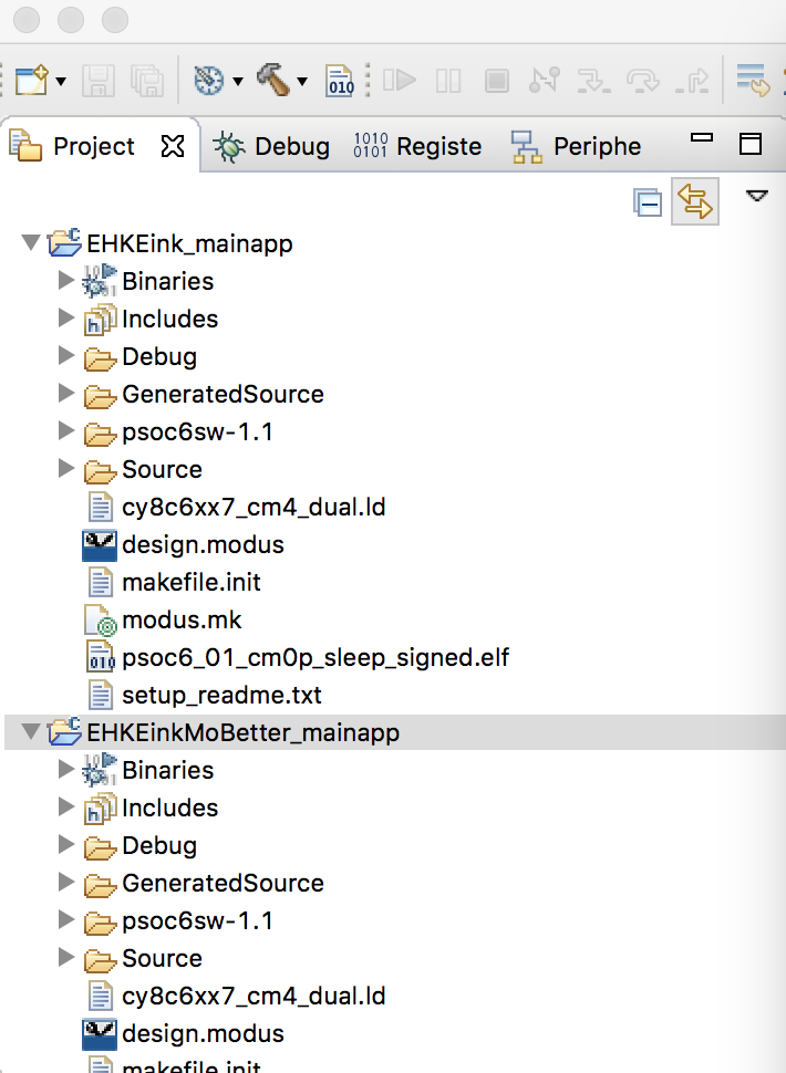
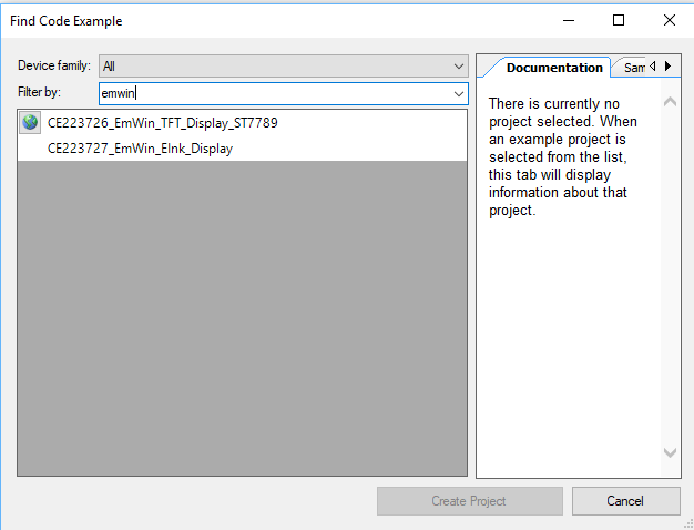
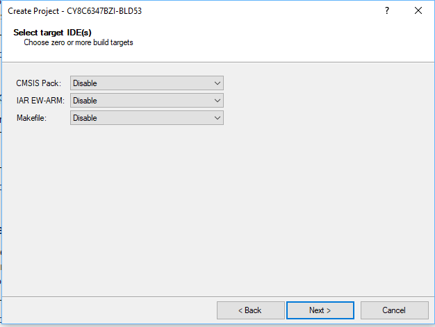
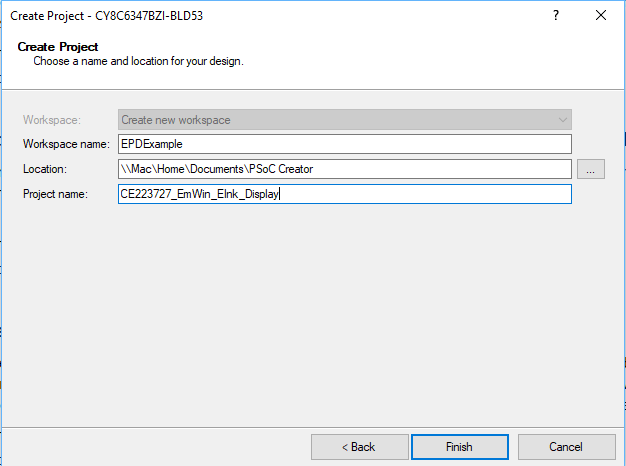
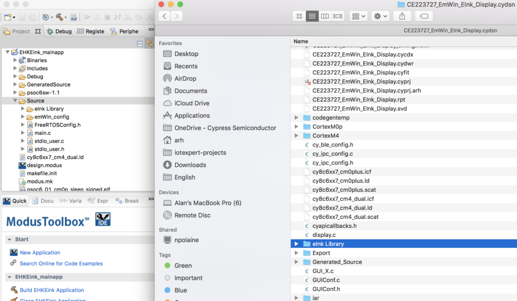
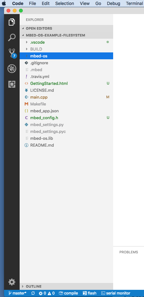
I want to start by creating a copy of the project from the previous article (so that alls yall can see the progression of code changes). In the previous article I walked you step-by-step through creating and copying a project. Here is a summary of the step you need to take. If you want to see the details please look at the last article.
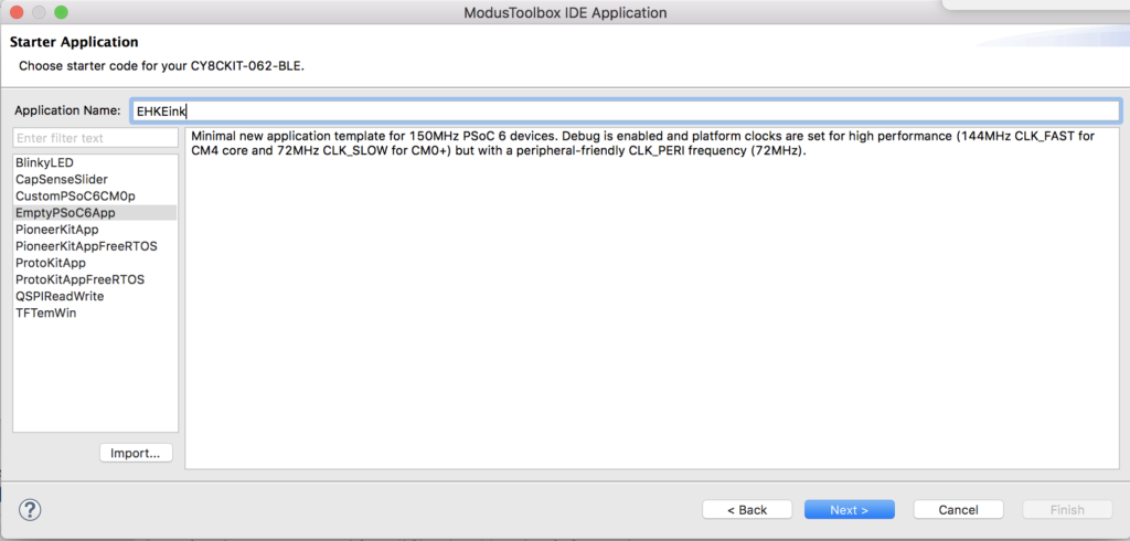
- Make a new project
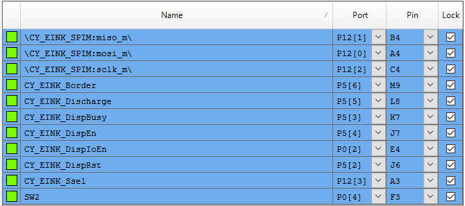
- Copy design.modus
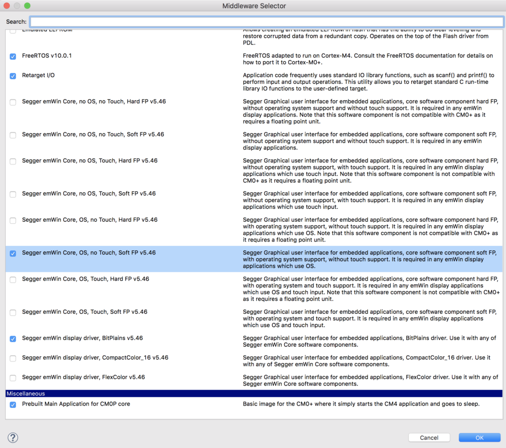
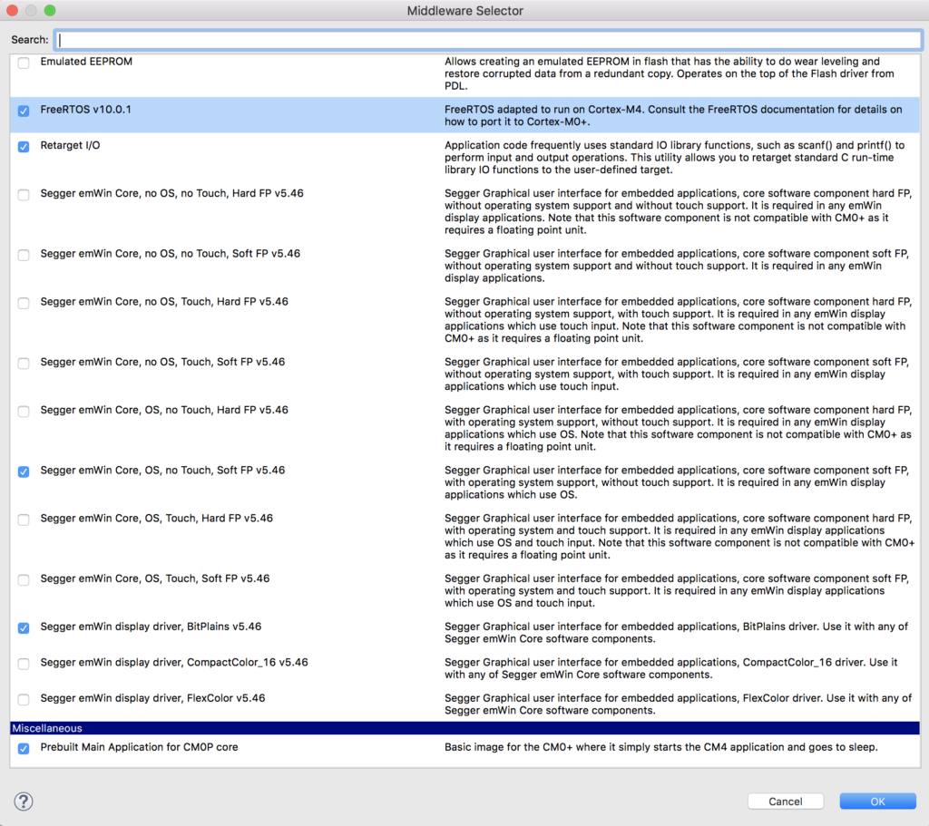
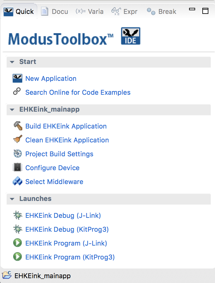
- Add the middleware (FreeRTOS, Segger Core OS NoTouch & Soft FP,Segger BitPlains, Retarget I/O)
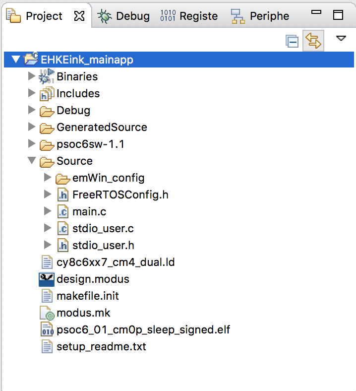
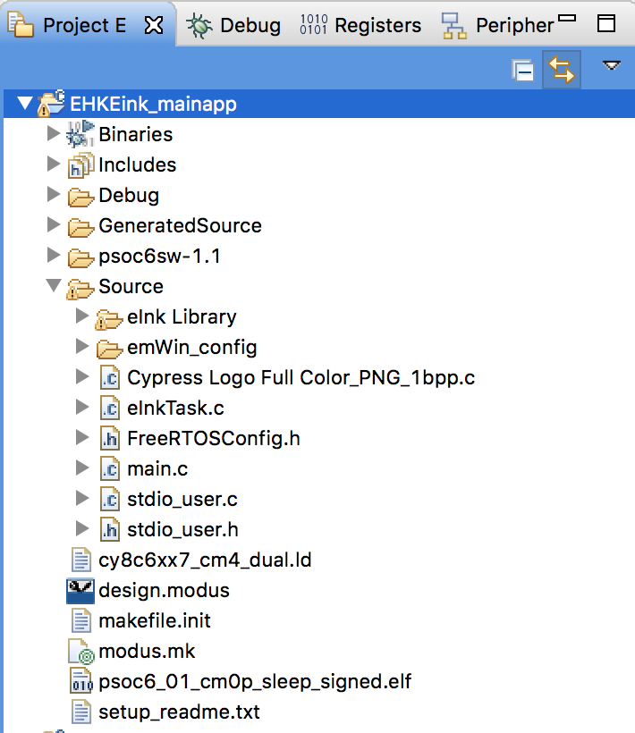
- Copy all of the files from the source directory
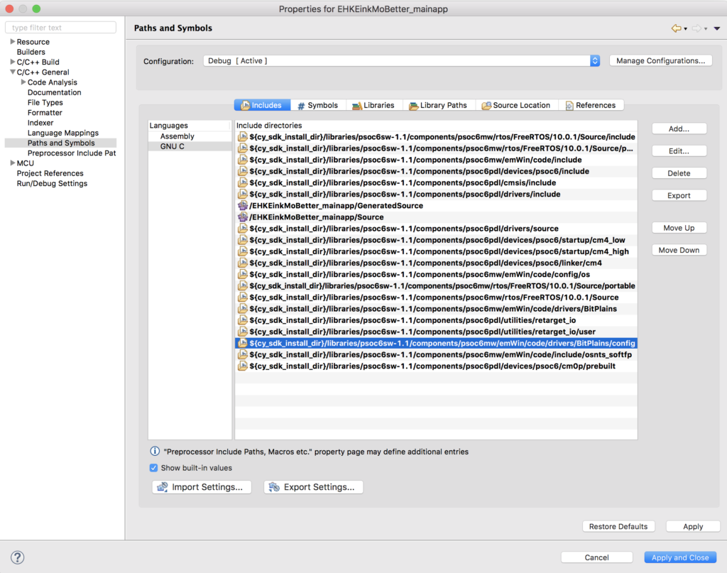
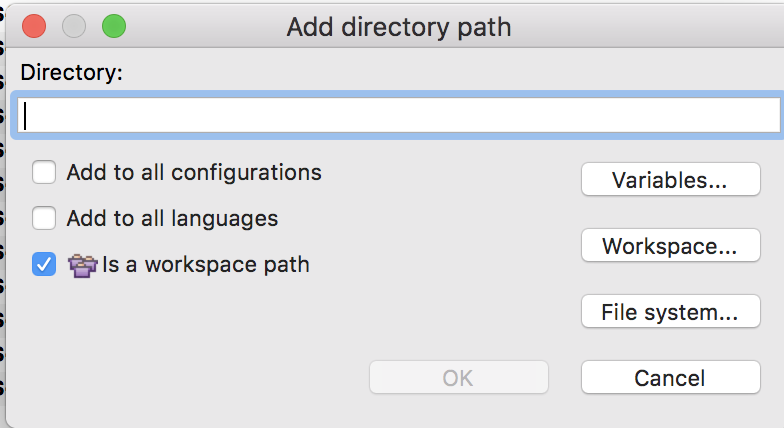
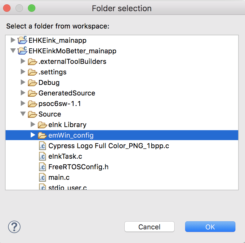
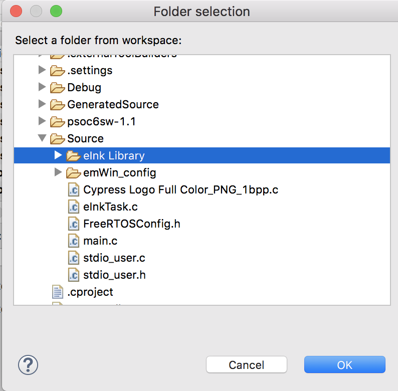
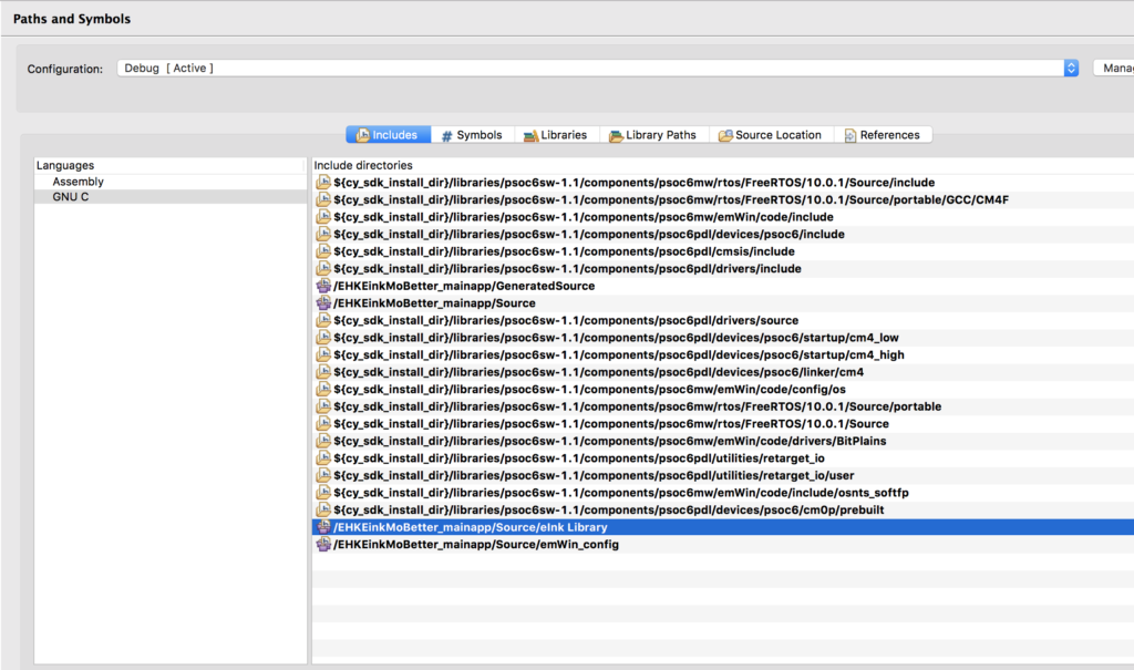
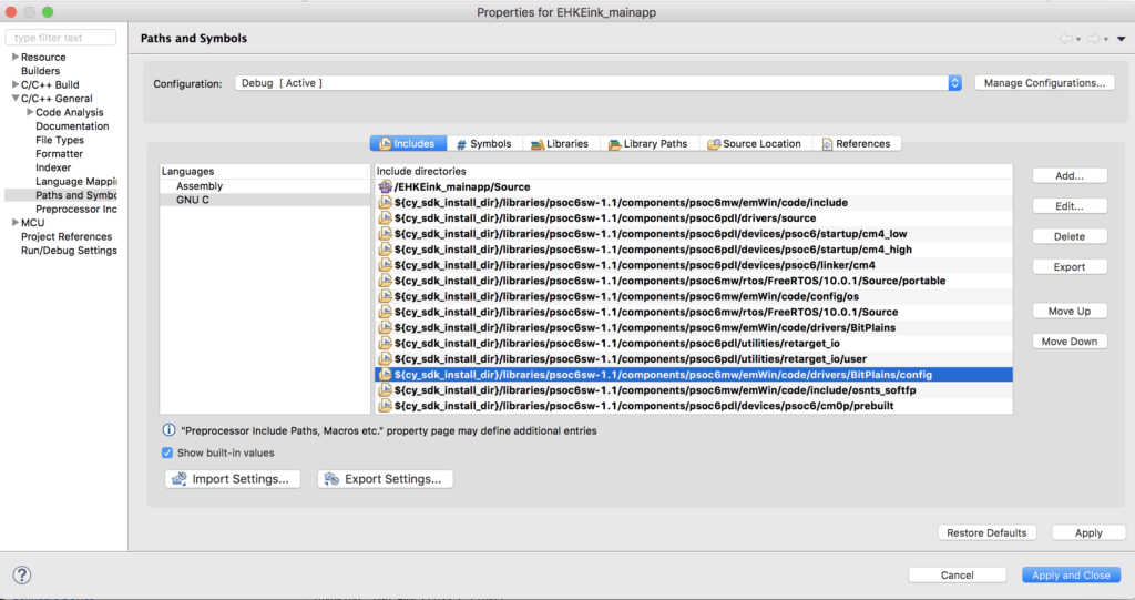
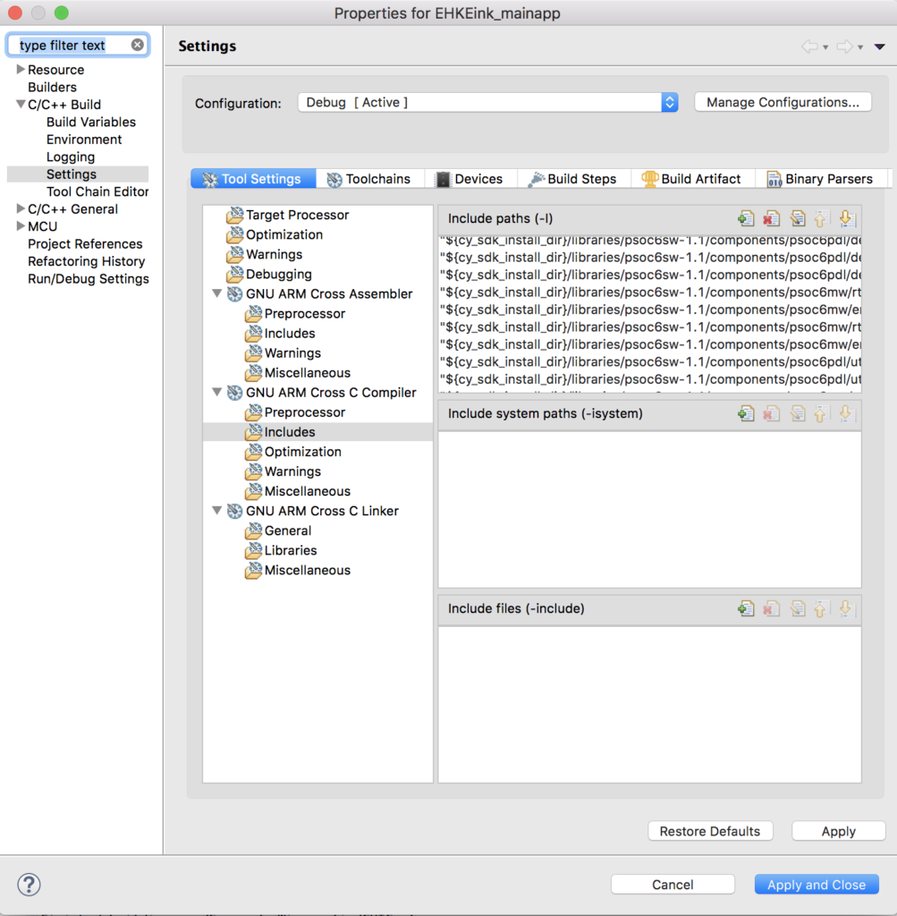
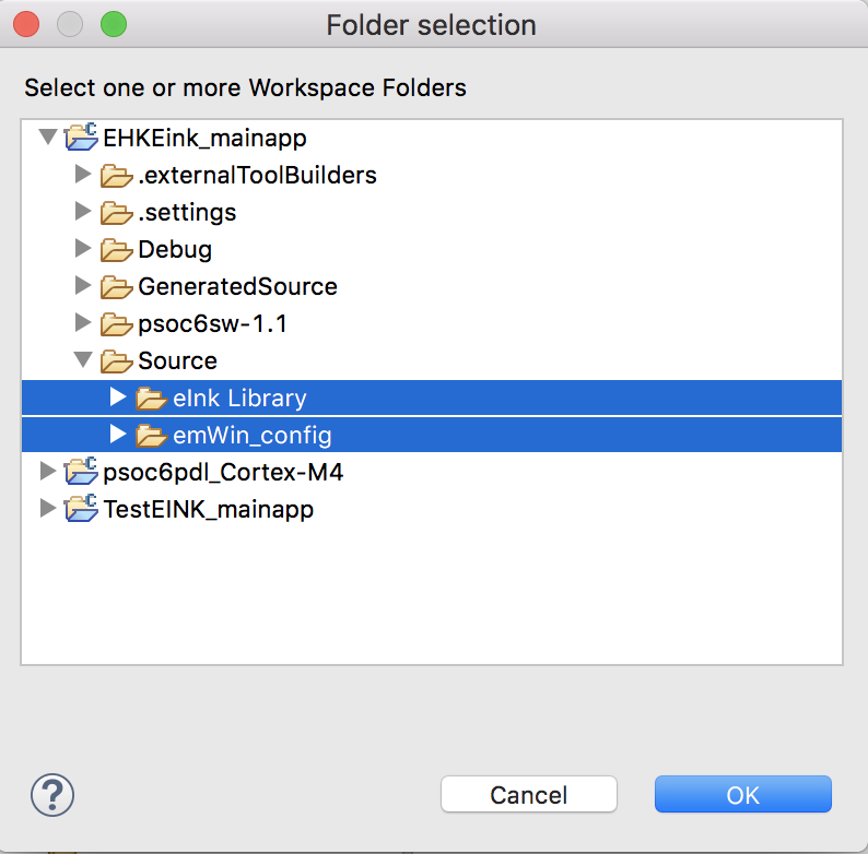
- Update the Include paths with the “eInk Library” and “emWin_Config”
After making all of these changes I will have a project in my workspace called “EHKEinkTiming”. I would recommend before you go further that you build and program to make sure that everything is still working.
Measure the SPI Speed Increase
All of the action to dump the frame buffer onto the EINK display happens in the function UpdateDisplay in the file eInkTask.c. In the code below you can see that I ask FreeRTOS what the count is before I dump the display, then what the count is after it is done.
void UpdateDisplay(cy_eink_update_t updateMethod, bool powerCycle)
{
    /* Copy the EmWin display buffer to imageBuffer*/
    LCD_CopyDisplayBuffer(imageBuffer, CY_EINK_FRAME_SIZE);

    uint32_t startCount = xTaskGetTickCount();
    /* Update the EInk display */
    Cy_EINK_ShowFrame(imageBufferCache, imageBuffer, updateMethod, powerCycle);
    uint32_t endCount = xTaskGetTickCount();
    printf("Update Display Time = %d\n",(int)(endCount - startCount));

    /* Copy the EmWin display buffer to the imageBuffer cache*/
    LCD_CopyDisplayBuffer(imageBufferCache, CY_EINK_FRAME_SIZE);
}
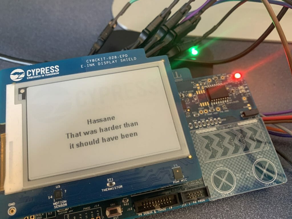
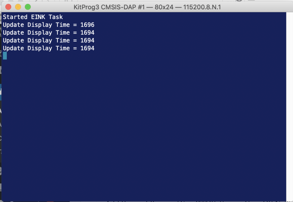
When I run the updated program I find that it takes about 1.7 seconds to update the screen.
Then I go back and modify the original program (before the SPI fixes) to see how long it takes…
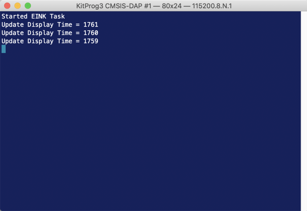
And yes if you can do math, which I’m sure everyone who has read this far can, you will notice that I only sped things up by 65 Milliseconds… which means you need to call bullshit on my original declaration that it was noticeably faster. Oh well at least I learned a bunch about the clock system.
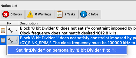
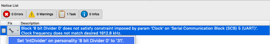
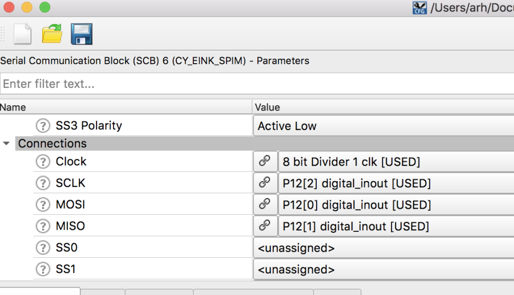
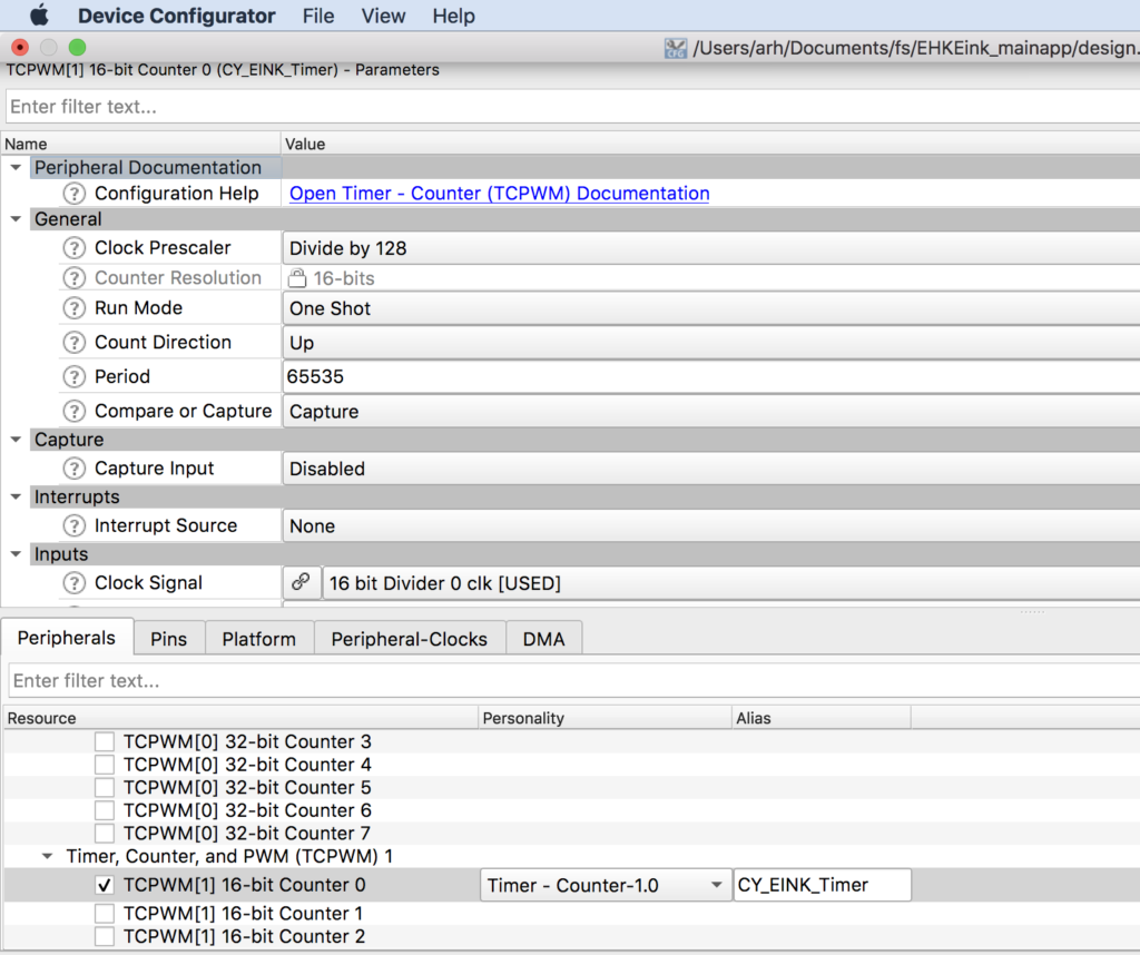
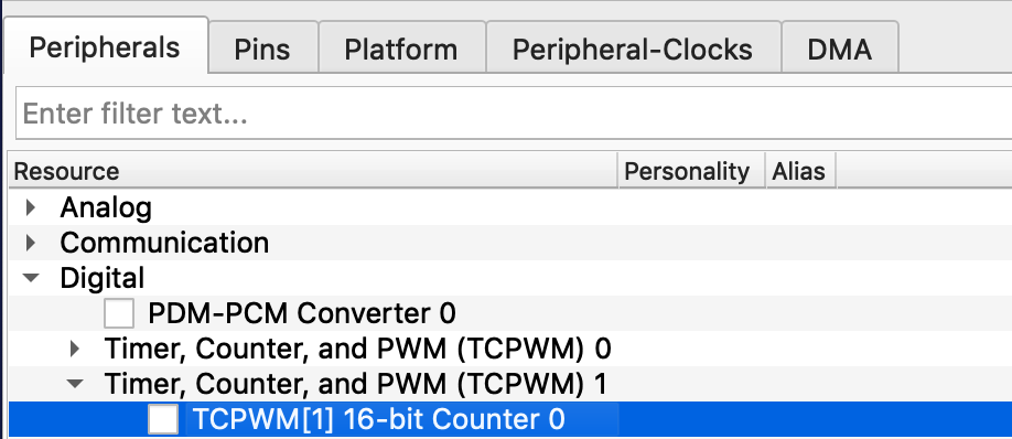
Remove the HW timer & Update the EINK Driver
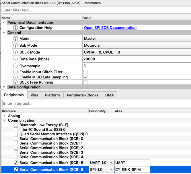
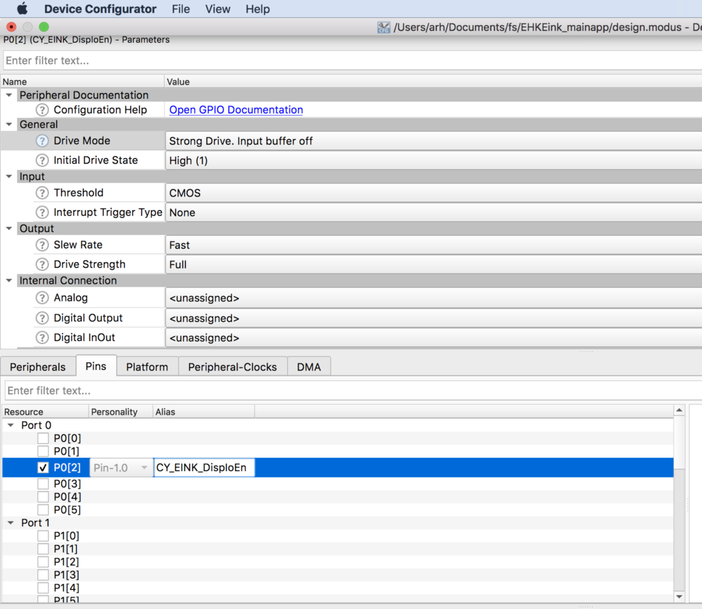
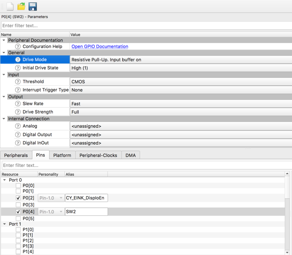
OK now that we have the hang of SysTick, it is clear that we don’t need the hardware timer that we put into the first project, so let’s get it out of there. Start by running design.modus and removing the timer. Just click the checkbox on “TCPWM[1]…” to turn it off. Then press save.
If you hit compile you will find a whole bunch of errors… but they are all in four functions inside of cy_eink_psoc_interface.c. Specifically
- Cy_EINK_TimerInit
- Cy_EINK_GetTimeTick
- Cy_EINK_TimerStop
To fix them Ill first create a global static variable called “timerCount”
static uint32_t timerCount;
Then update Cy_EINK_TimerInit to just store the current FreeRTOS timer value in my new global variable.
void Cy_EINK_TimerInit(void)
{
	timerCount = xTaskGetTickCount();
}
Next update Cy_EINK_GetTimeTick to return the number of ticks since the timer was initialized.
uint32_t Cy_EINK_GetTimeTick(void)
{
	    /* Return the current value of time tick */
    return(xTaskGetTickCount()-timerCount);
}
Finally, make the TimerStop function do… well… nothing.
void Cy_EINK_TimerStop(void)
{
}
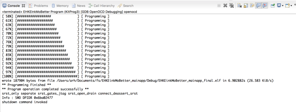
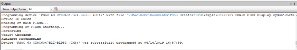
When I build and program… my project is off to the races without the hardware timer.
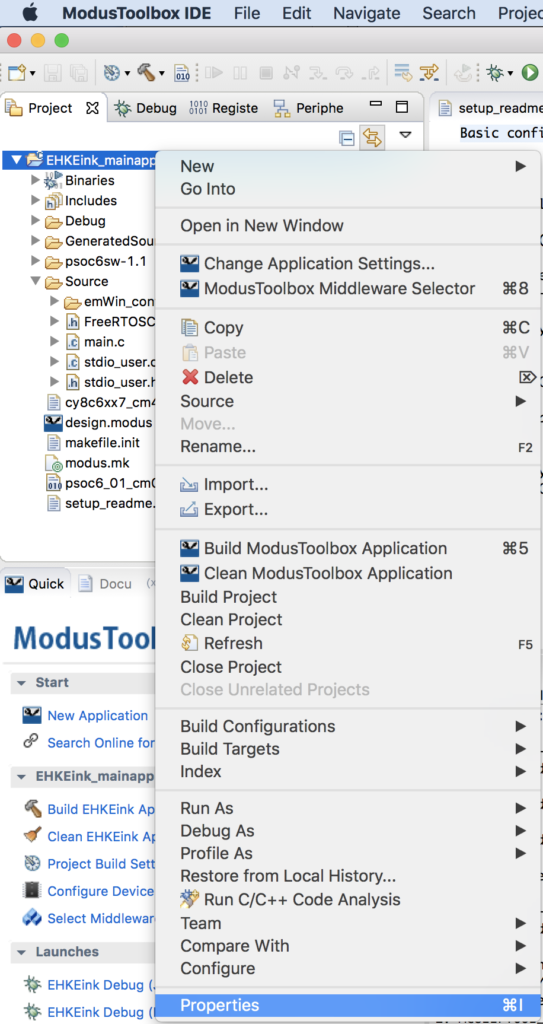
In the next article Ill have a look at the EINK datasheet and driver to look into how it works.