Summary
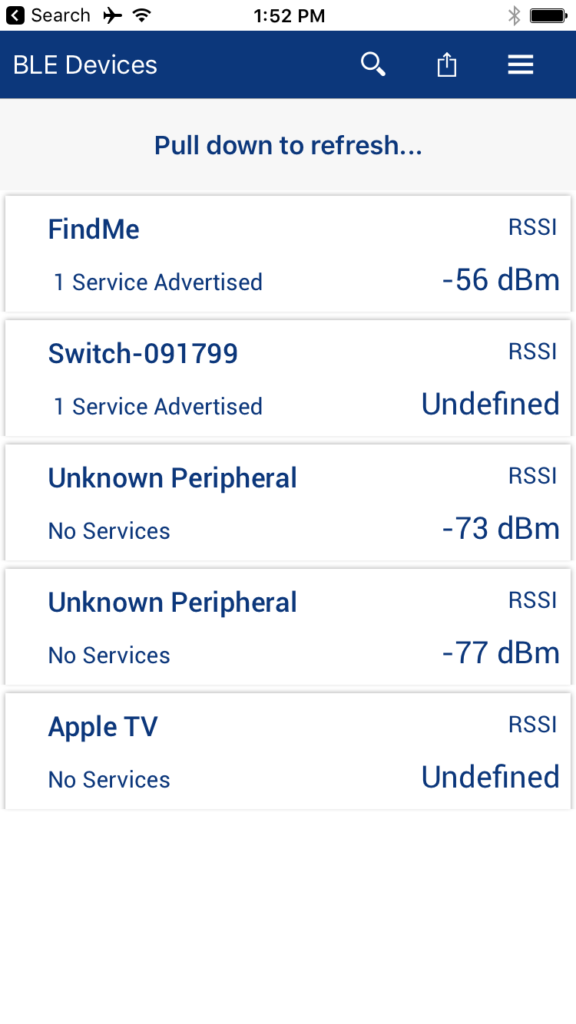
I have been working on making some new videos for Cypress about the PSoC 6 BLE. Everyone always likes to start with an easy BLE example, and the go to example is the “Find Me”. I started by building a Find Me Profile example, but when I looked my example I decided that I wanted to trace the actual application all the way back to the Bluetooth Special Interest Group (SIG) specification. So, that is exactly what I do for this article.
- Bluetooth SIG Find Me Profile
- Bluetooth SIG Immediate Alert Service
- Configure PSoC 6 BLE Schematic & Pins
- Setup FreeRTOS and Retarget I/O
- PSoC 6 BLE Firmware Architecture
- Firmware for the alertTask
- Firmware for the Immediate Alert Service Callback
- Firmware for the BLE Callback
- Firmware for the BLE Task
- Firmware to start the system
Bluetooth SIG Find Me Profile
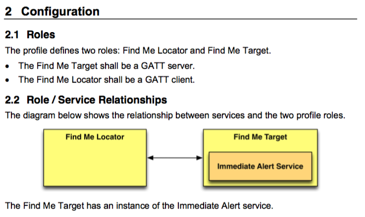
The Bluetooth SIG defines a bunch of standard profiles. A standard Profile is just some combination of standardized Services and Characteristics. One of those Profiles is the Find Me Profile. The concept behind the Find Me Profile was that you could connect to a device with the Find Me Profile, and then send it an alert, at which point it would start “alerting” (presumably blinking or beeping). You could imagine a tag attached to your car keys for instance. You can get the Find Me Profile Specification from the Bluetooth SIG website. The spec is a 10ish page pdf that says a Find Me Profile is just a device with an Immediate Alert Service server or client. Here is a picture from the spec:
The other interesting part of the specification defines how the advertising is supposed to work

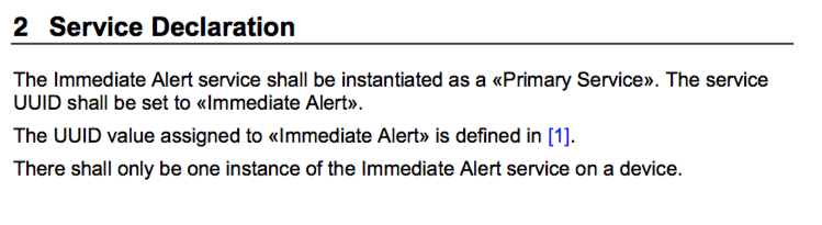
Immediate Alert Service
But, what is an Immediate Alert Service? Well, you can get the Immediate Alert Service specification from the Bluetooth SIG website as well. It basically says that there is one Service called Immediate Alert with a UUID of 0x1802 and that Service has one Characteristic called “Alert Level” with a UUID of 0x2A06. Here is a screen shot.
Unfortunately the spec doesnt have the UUIDs in it, and you have to follow the [1] to the website. On the Bluetooth SIG GATT Services UUID definition webpage you can see the UUID of the Immediate Alert Service (0x1802)
![]()
And on the Bluetooth SIG GATT Characteristics definition webpage you can see the UUID of the Alert Level (0x2A06)
![]()
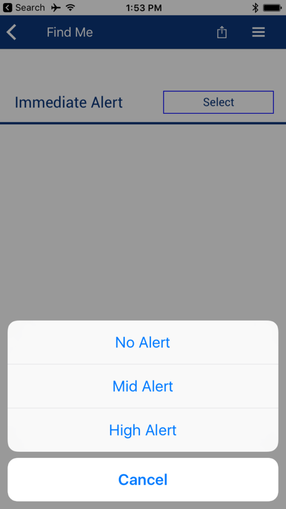
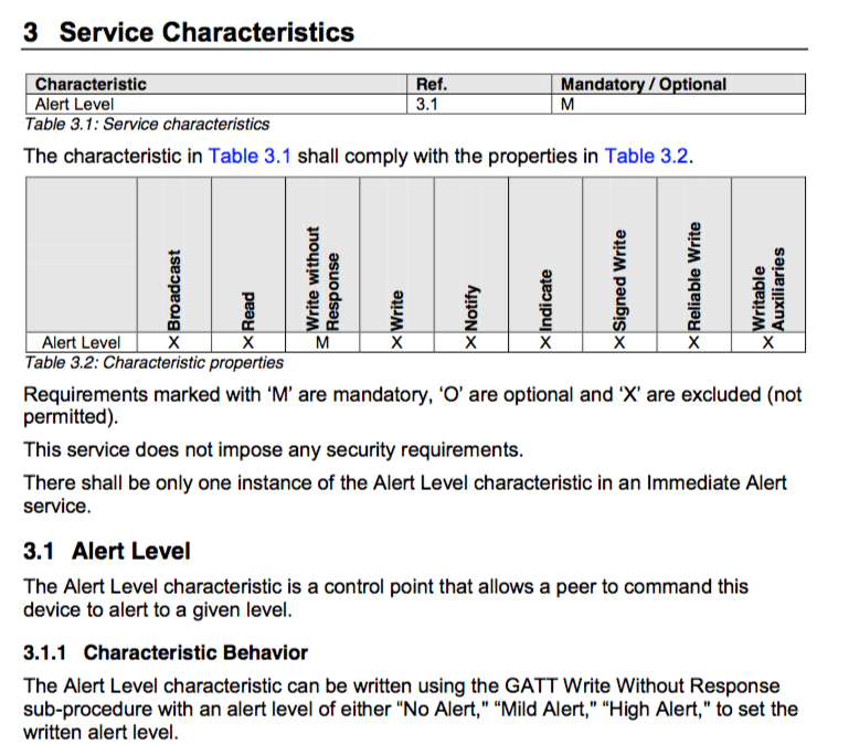
It also says the alert characteristic is writable with three values (No, Mild, High) and if you click on Alert Level you can see the definition of those:
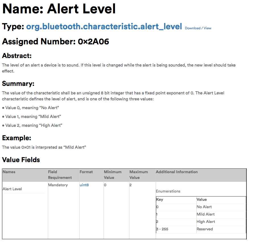
Next you can see information about the Alert Characteristic.
Configure PSoC 6 BLE Schematic & Pins
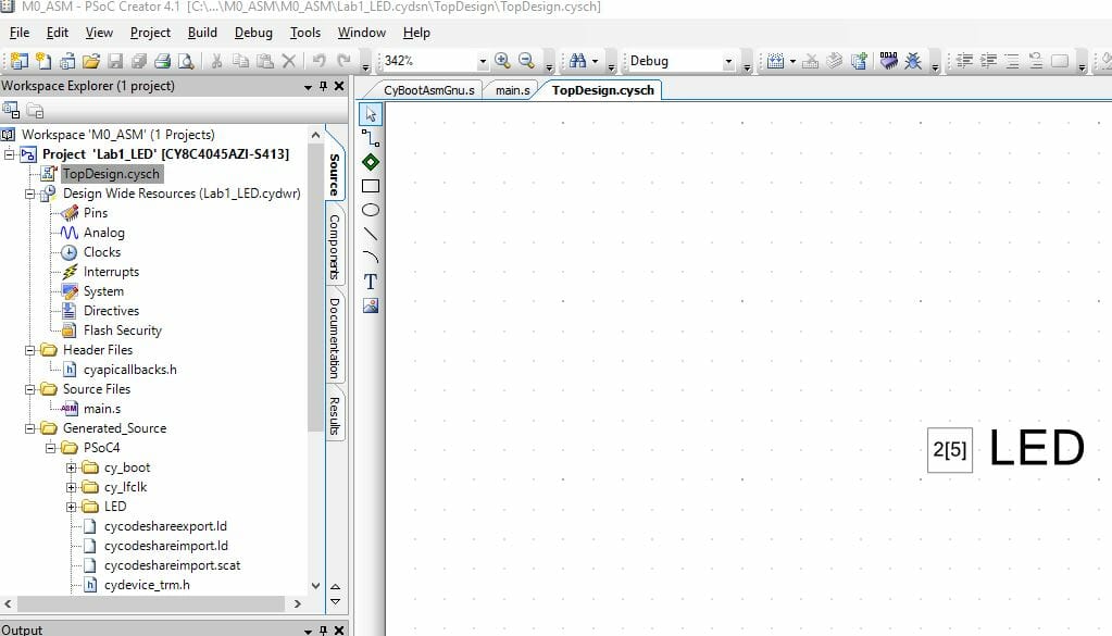
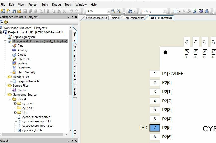
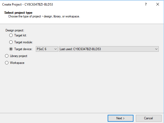
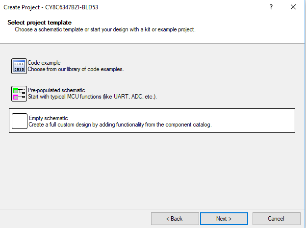
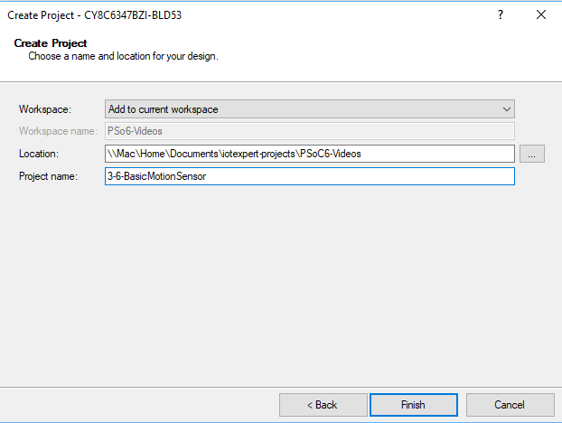
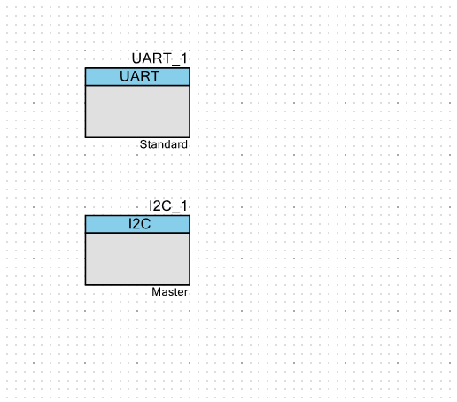
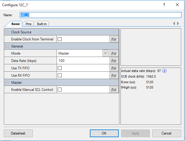
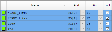
Now, lets build the project. Create a new PSoC 6 BLE project and edit the schematic to have a BLE, UART, and two digital output pins (red, led9).
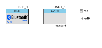
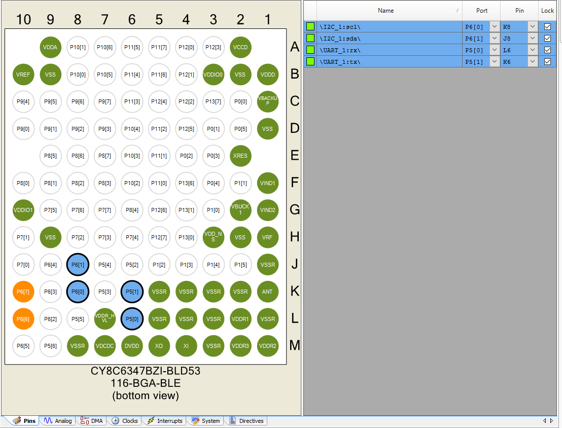
Assign the pins to the correct place on the CY8CKIT-062-BLE development kit. I am going to use led9 to show when the device is connected (or not)
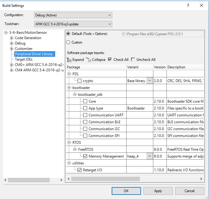
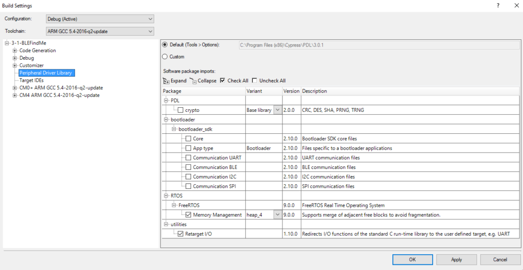
Change the build settings to add FreeRTOS (Heap 4) and Retarget I/O
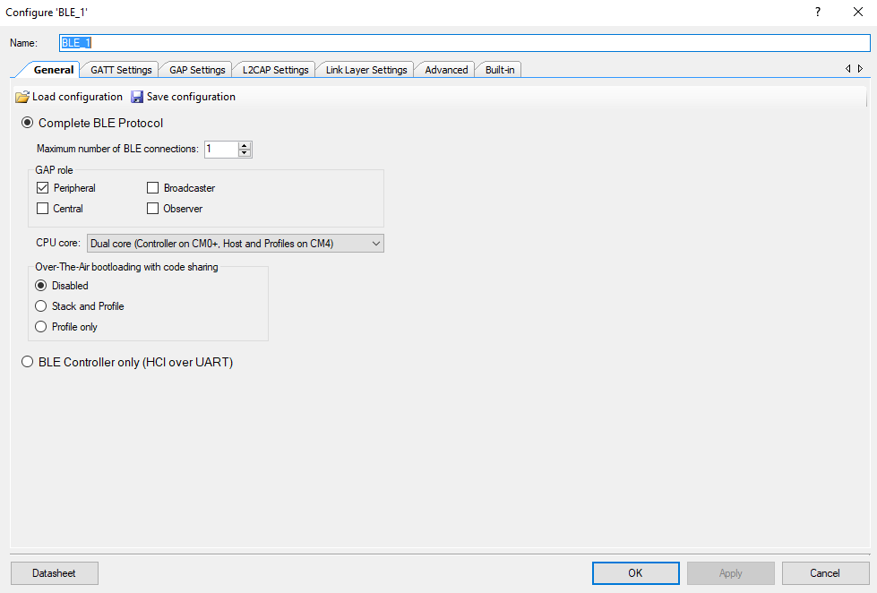
Configure the BLE to be dual core and a peripheral
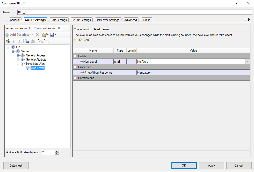
Add the Find Me Target (GATT Server) profile

Once that is done you will see the Immediate Alert Service (with the correct UUID from above)

And the Alert Level with the correct UUID
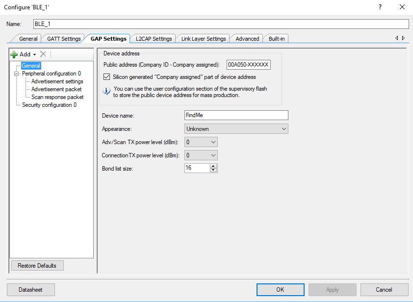
Next give the device a name (“FindMe”)
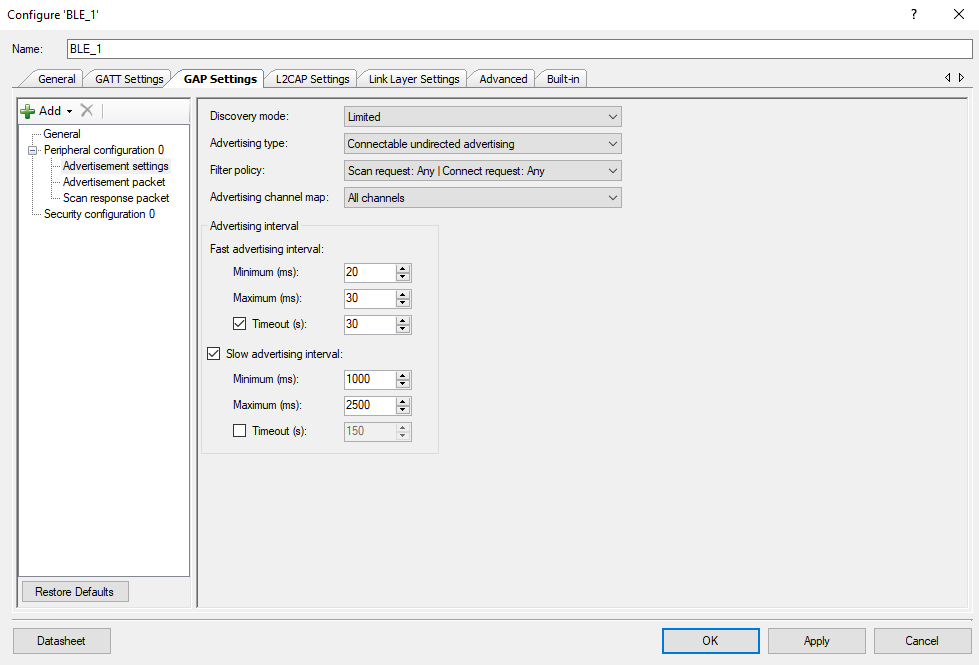
The spec calls for the advertising setup to be as follows
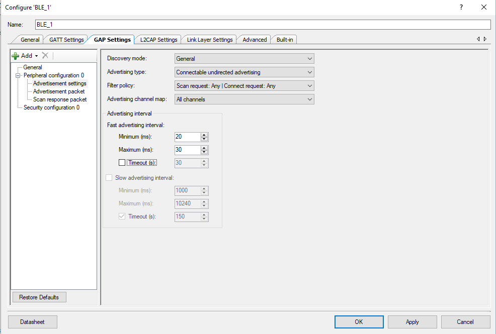
But I have to admit that I dont like to wait… so I configured it like this:
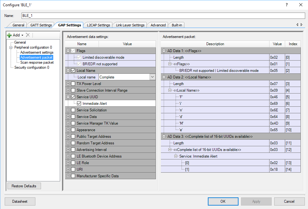
Next, configure the advertising packet to have the name of the device and the fact that it has a IAS Service
Setup FreeRTOS and Retarget I/O
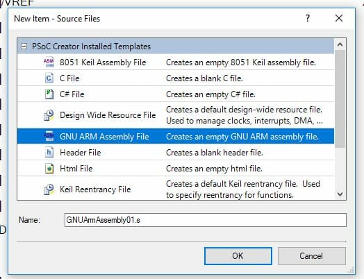
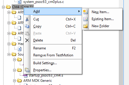
Run “Generate Application” to bring in all of the BLE and PDL firmware. Then edit “stdio_user.h” to setup the stdio support.
#include "project.h"
/* Must remain uncommented to use this utility */
#define IO_STDOUT_ENABLE
#define IO_STDIN_ENABLE
#define IO_STDOUT_UART      UART_1_HW
#define IO_STDIN_UART       UART_1_HW
Next, modify FreeRTOSConfig.h to include support for semaphores.
#define configUSE_COUNTING_SEMAPHORES 1
and a much bigger stack
#define configTOTAL_HEAP_SIZE (48*1024)
And finally the interrupts to support BLE
/* Put KERNEL_INTERRUPT_PRIORITY in top __NVIC_PRIO_BITS bits of CM4 register */
#define configKERNEL_INTERRUPT_PRIORITY         0xFF
/* Put MAX_SYSCALL_INTERRUPT_PRIORITY in top __NVIC_PRIO_BITS bits of CM4 register */
//#define configMAX_SYSCALL_INTERRUPT_PRIORITY    0xBF
#ifdef __NVIC_PRIO_BITS
      /* __BVIC_PRIO_BITS will be specified when CMSIS is being used. */
      #define configPRIO_BITS                   __NVIC_PRIO_BITS
#else
      #define configPRIO_BITS                   4        /* 15 priority levels */
#endif

#define configMAX_SYSCALL_INTERRUPT_PRIORITY    ( 1 << (8 - configPRIO_BITS) )
Firmware Architecture
There will be two tasks
- The alertTask which will be responsible for setting the state of the red LED. To set the state of the LED any other task can set the EventGroup bits.
- The bleTask which will handle running the BLE and the generic BLE callback and the IAS callback.
Firmware for the alertTask
The alert task will
- Set things up including eventBits which I call “alertState”
- Turn off the red led
- Go into an infinite loop
- The loop will either 1) wait until the end of time or 2) timeout at 500ms)
- Then it will determine the cause of the timeout and set the state of the red LED
// These BITs are used to set the state of the red LED
EventGroupHandle_t alertState;
#define ALERT_NO_MASK   1<<0
#define ALERT_MILD_MASK 1<<1
#define ALERT_HIGH_MASK 1<<2

/*****************************************************************************\
 * Function:    alertTask
 * Input:       FreeRTOS Template - unused argument
 * Returns:     void
 * Description:
 *     This funtion is the mainloop for the alertTask.  It manages the state of
 *     the RED led.  Other tasks communitcate with this task using the alertState
 *     event bits.
\*****************************************************************************/
void alertTask(void *arg)
{
    (void)arg;
    printf("Alert Task Started\r\n");
    TickType_t delay=portMAX_DELAY;
    EventBits_t currentBits;

    alertState = xEventGroupCreate();
    xEventGroupSetBits(alertState,ALERT_NO_MASK);

    Cy_GPIO_Write(red_PORT,red_NUM,LED_OFF);

    while(1)
    {
        currentBits = xEventGroupWaitBits(alertState,ALERT_HIGH_MASK|ALERT_MILD_MASK|ALERT_NO_MASK,
            pdTRUE,pdFALSE,delay);
        switch(currentBits)
        {
            case ALERT_NO_MASK:
                delay = portMAX_DELAY;
                Cy_GPIO_Write(red_PORT,red_NUM,LED_OFF);
            break;
            case ALERT_HIGH_MASK:
                delay = portMAX_DELAY;
                Cy_GPIO_Write(red_PORT,red_NUM,LED_ON);
            break;
            case 0: // case 0 means timer expired & no bits set.
            case ALERT_MILD_MASK:
                delay = 500;
                Cy_GPIO_Inv(red_PORT,red_NUM);
            break;
        }
    }
}
Firmware for the Immediate Alert Service Callback
Cypress setup a bunch of APIs that know how to handle a bunch of the Bluetooth SIG Profiles/Services. First lets look at the PSoC 6 BLE Middleware PDL Documentation to find the IAS Service. It is in the “BLE Service-Specific API” section.
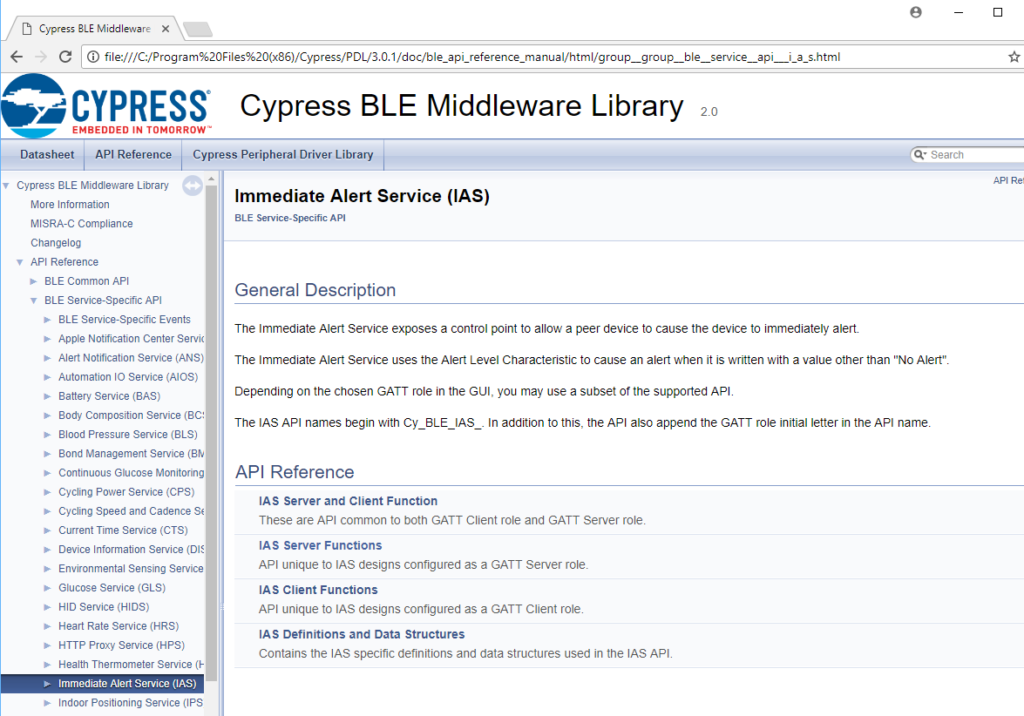
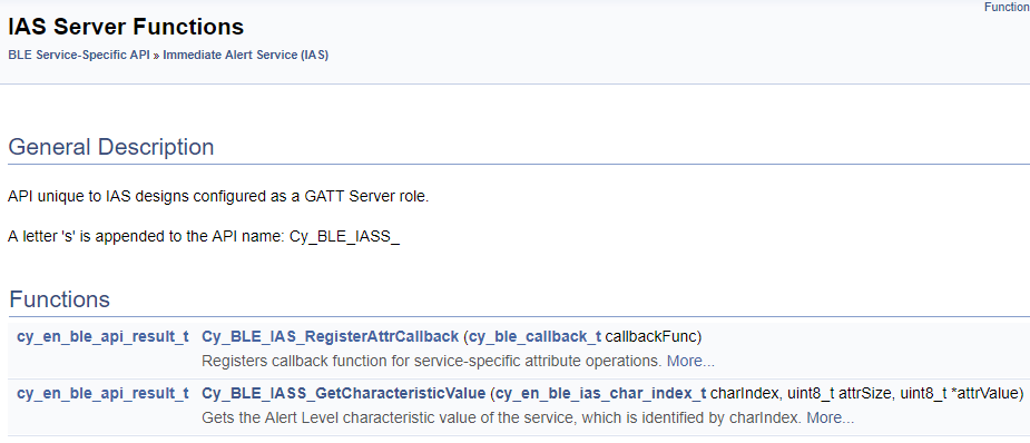
We want to implement a “GATT Server”… meaning our device has the IAS Server running on it so that a GATT Client can write into our database. When I click on “IAS Server Functions” it takes me to this section of the documentation. Basically what you do in your firmware is
- Register a callback with Cy_BLE_IAS_RegisterAttrCallback
- Setup the function that will be called back when the Alert Level characteristic is written.
Here is the documentation for the callback. You can see that you need to make a function that matches the prototype of “cy_ble_callback_t”)
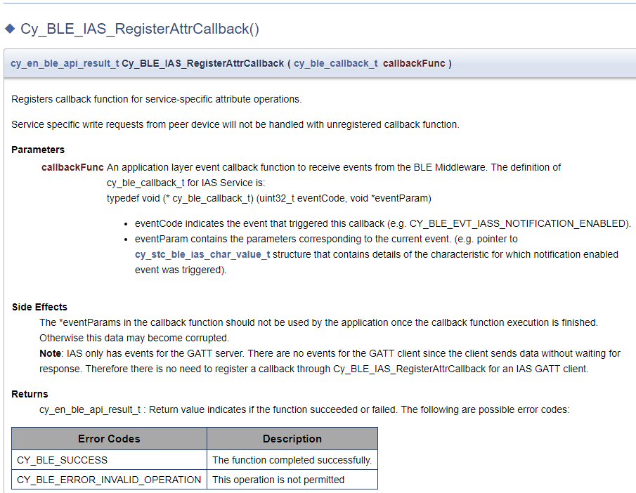
When you are called back you will get a void * which you can then cast into a pointer of type “cy_stc_ble_ias_char_value_t *”. This structure will contain the value of the alert in the “cy_stc_ble_gatt_value_t *value” member.
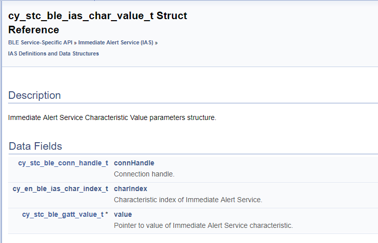
If you look at the “cy_stc_ble_Gatt_value_t” structure you will find that it contains a pointer to an array of uint8_t (actually one one)

Now to actually write the callback function. It just:
- Looks and sees if it is a write callback
- finds the value using the “Cy_BLE_IASS_GetCharacteristicValue” function.
- Then sends a message to the alertTask
/*****************************************************************************\
 * Function:    iasCallback
 * Input:       BLE IAS Service Handler Function:
 *      - eventCode (which only can be CY_BLE_EVT_IASS_WRITE_CHAR_CMD
 *      - eventParam which is a pointer to  (and unused)
 * Returns:     void
 * Description:
 *   This is called back by the BLE stack when there is a write to the IAS
 *   service.  This only occurs when the GATT Client Writes a new value
 *   for the alert.  The function figures out the state of the alert then
 *   sends a message to the alertTask usign the EventGroup alterState
\*****************************************************************************/
void iasCallback(uint32_t eventCode, void *eventParam)
{
    (void)eventParam;
    uint8_t alertLevel;

    if(eventCode == CY_BLE_EVT_IASS_WRITE_CHAR_CMD)
    {
        /* Read the updated Alert Level value from the GATT database */
        Cy_BLE_IASS_GetCharacteristicValue(CY_BLE_IAS_ALERT_LEVEL,
            sizeof(alertLevel), &alertLevel);

        // The value of the characteristic could also be gotten like this:
        //switch(((cy_stc_ble_ias_char_value_t *)eventParam)->value->val[0])

        switch(alertLevel)
        {
            case CY_BLE_NO_ALERT:
                printf("No alert\n");
                xEventGroupSetBits(alertState,ALERT_NO_MASK);
            break;
            case CY_BLE_MILD_ALERT:
                printf("Medium alert\n");
                xEventGroupSetBits(alertState,ALERT_MILD_MASK);
            break;
            case CY_BLE_HIGH_ALERT:
                printf("High alert\n");
                xEventGroupSetBits(alertState,ALERT_HIGH_MASK);
            break;
        }
    }
}
Instead of calling the function to get the values, you could have also been done this:
switch(((cy_stc_ble_ias_char_value_t *)eventParam)->value->val[0])
Firmware for the Ble Event Handler
The BLE event handler is really simple, it just prints out some debugging information depending on the event. It also starts the advertising when the stack starts or when it has been disconnected.
/*****************************************************************************\
 * Function:    customEventHandler
 * Input:       Cy_BLE Event Handler event and eventParameter
 * Returns:     void
 * Description:
 *   This funtion is the BLE Event Handler function.  It is called by the BLE
 *   stack when an event occurs
\*****************************************************************************/
void customEventHandler(uint32_t event, void *eventParameter)
{
    (void)eventParameter; // not used
    switch (event)
    {
        case CY_BLE_EVT_STACK_ON:
            printf("Stack Started\r\n");
            Cy_BLE_GAPP_StartAdvertisement(CY_BLE_ADVERTISING_FAST, CY_BLE_PERIPHERAL_CONFIGURATION_0_INDEX);
        break;

        case CY_BLE_EVT_GAP_DEVICE_DISCONNECTED:
            printf("Disconnected\r\n");
            Cy_GPIO_Write(led9_PORT,led9_NUM,LED_OFF); // Turn the LED9 Off
            Cy_BLE_GAPP_StartAdvertisement(CY_BLE_ADVERTISING_FAST, CY_BLE_PERIPHERAL_CONFIGURATION_0_INDEX);
        break;

        case CY_BLE_EVT_GATT_CONNECT_IND:
            printf("Connected\r\n");
            Cy_GPIO_Write(led9_PORT,led9_NUM,LED_ON); // Turn the LED9 On
        break;

        default:
        break;
    }
}
Firmware for the bleTask
The bleTask has two functions
- an ISR that is called whenever an IPC event happens (so that it can unlock the semaphore to process events)
- a main function which starts the system, registers the callback and runs process events at the right time.
/*****************************************************************************\
 * Function:    bleInterruptNotify
 * Input:       void (it is called inside of the ISR)
 * Returns:     void
 * Description:
 *   This is called back in the BLE ISR when an event has occured and needs to
 *   be processed.  It will then set/give the sempahore to tell the BLE task to
 *   process events.
\*****************************************************************************/
void bleInterruptNotify()
{
    BaseType_t xHigherPriorityTaskWoken;
    xHigherPriorityTaskWoken = pdFALSE;
    xSemaphoreGiveFromISR(bleSemaphore, &xHigherPriorityTaskWoken);
    portYIELD_FROM_ISR( xHigherPriorityTaskWoken );
}

/*****************************************************************************\
 * Function:    bleTask
 * Input:       A FreeRTOS Task - void * that is unused
 * Returns:     void
 * Description:
 *  This task starts the BLE stack... and processes events when the bleSempahore
 *  is set by the ISR.
\*****************************************************************************/

void bleTask(void *arg)
{
    (void)arg;

    printf("BLE Task Started\n");

    bleSemaphore = xSemaphoreCreateCounting(UINT_MAX,0);

    Cy_BLE_Start(customEventHandler);
    Cy_BLE_IPC_RegisterAppHostCallback(bleInterruptNotify);

    while(Cy_BLE_GetState() != CY_BLE_STATE_ON) // Get the stack going
    {
        Cy_BLE_ProcessEvents();
    }

    Cy_BLE_IAS_RegisterAttrCallback (iasCallback);
    for(;;)
    {
        xSemaphoreTake(bleSemaphore,portMAX_DELAY);
        Cy_BLE_ProcessEvents();
    }
}
Main Firmware
Finally the main firmware just starts all of the tasks.
// Starts the system
int main(void)
{
    __enable_irq();

    UART_1_Start();
    setvbuf( stdin, NULL, _IONBF, 0 );
    setvbuf( stdout, NULL, _IONBF, 0 );
    printf("System Started\r\n");

    xTaskCreate(bleTask,"bleTask",8*1024,0,2,&bleTaskHandle);
    xTaskCreate(alertTask,"AlertTask",configMINIMAL_STACK_SIZE,0,1,0);

    vTaskStartScheduler();
    for(;;)
    {
    }
}
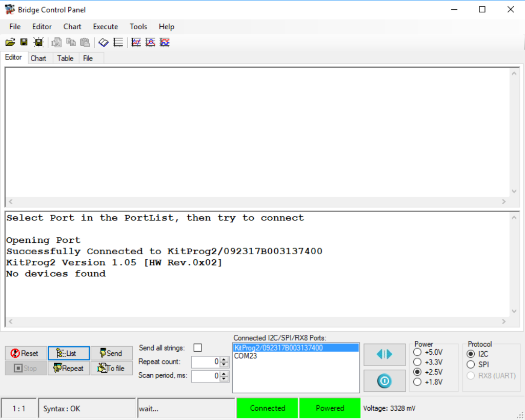
Test
After doing all of this, you can run CySmart to test the system: