The good news is that the Robot Arm arrived from Amazon, which I was very happy about because it was a day late. The even better news is that it works like a charm. First I needed to assemble it, which I did with a little bit of help from my able lab technician and a trip to Lowe’s to get a base.
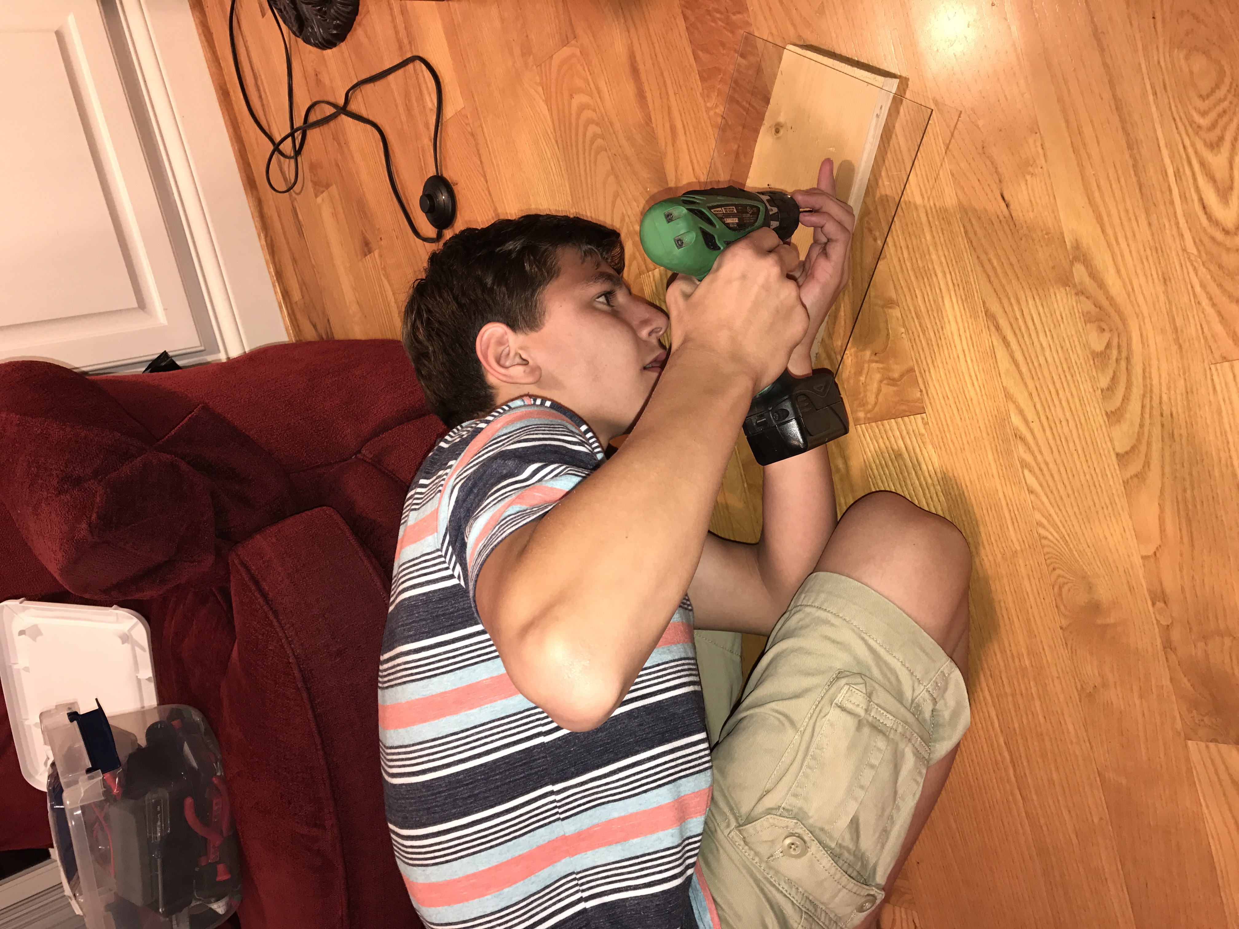
Then “we” attached the base to the Robot.
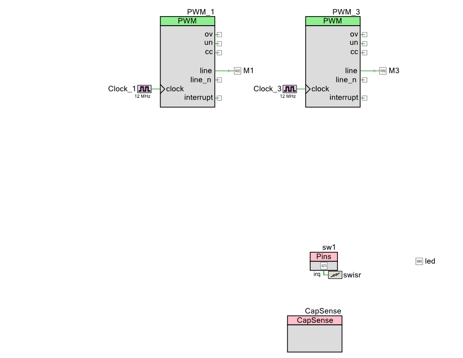
After the robot arm was put together on the base, I needed a little bit of firmware to run it. First the schematic: You can see that I have
- Two PWMs – one for each Servo motor
- A Capsense slider to move one of the axis on the robot
- A switch and LED to turn On/Off the PWMs
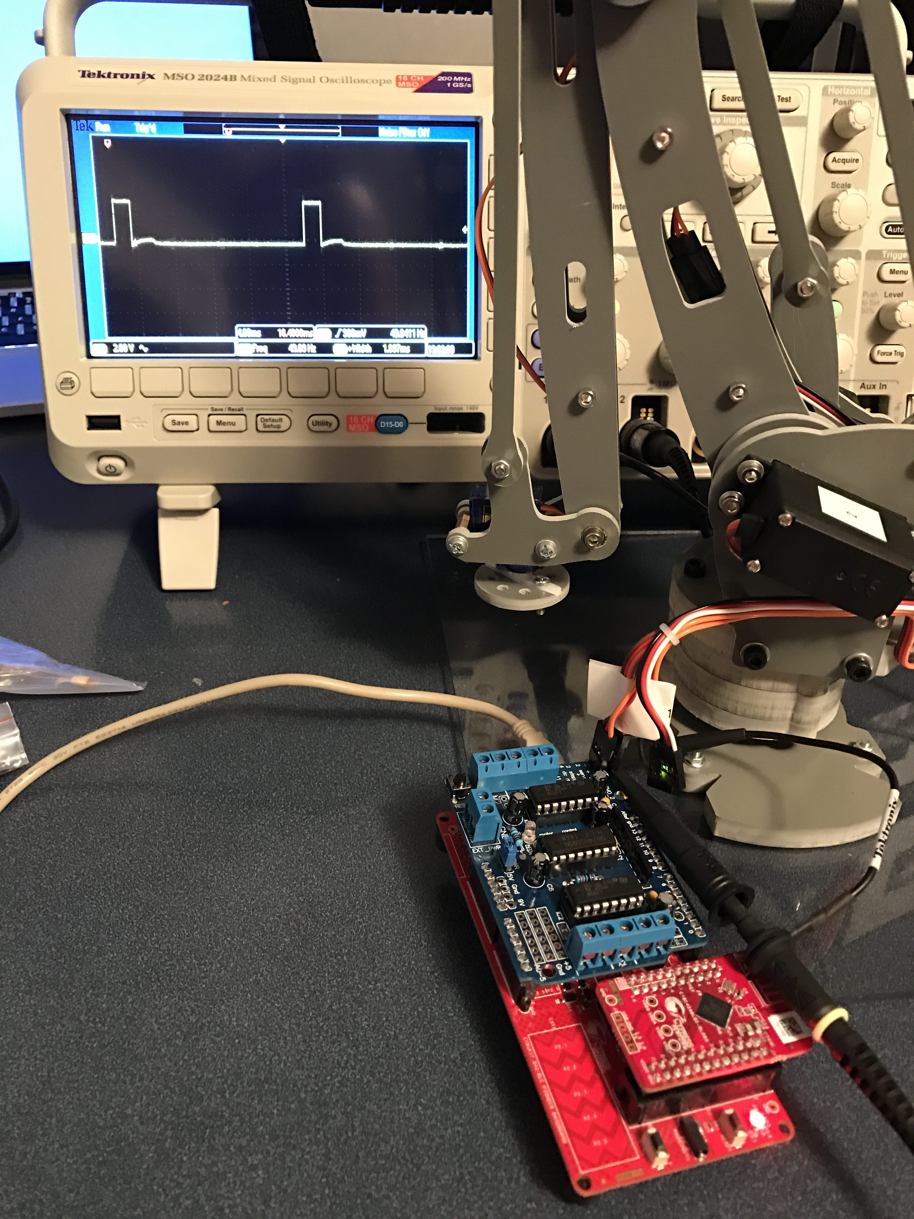
The robot arm has 4 “axis” which are each controlled by “servo” motors. Servo motors have a small controller built into them that takes an input signal that is created by a PWM and turns the motor to the right place. To drive the motor you need a input signal that is 50HZ, with a high pulse that ranges from ABOUT 1ms to 2ms. When the pulse is 1ms the motor is all the way one direction, when the pulse is 2ms it is all the way the other direction. To make the motor do what you want you give it a pulse somewhere in the middle, for instance if you want it to be half way then the pulse width is 1.5ms.
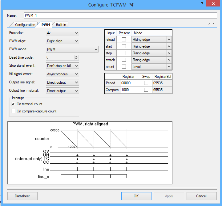
The easiest way to make this work is with a Pulse Width Modulator (PWM). Conveniently enough, the PSoC4 BLE that I am using to build this project has 4 of them. I set the input clock on the PWM to 12MHz, then I turned on the prescaler to divide by 4. I then set the period to 60000. Given all of that, the output frequency is 50hz. which you can calculate by 12,000,000 / 4 / 60,000 = 50. Given the period is 50HZ and there are 60000 clock ticks per period, each tick is 3us. To make things easier on the rest of the system I want to give the input a range between 0% and 100% (as an Integer). This lets me calculate the number of ticks I need to set the pulse width. The formula is 3*(1000 + 10*percent). I determined this empirically with an oscilloscope and changing the values to see the range of motion of the Robot Arm.
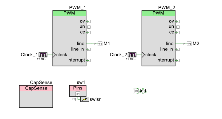
To achieve all of this, the PWM configuration is:
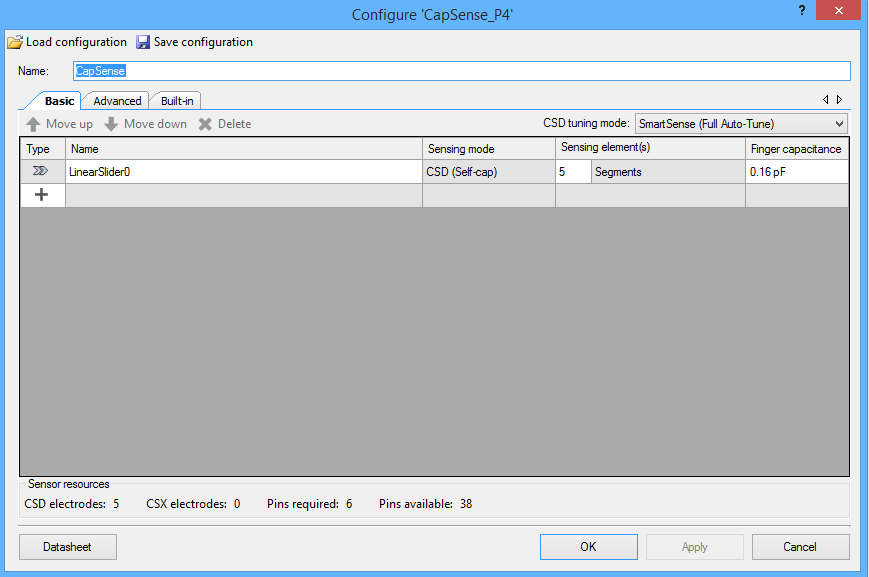
Now I configure the CapSense block to have a linear slider.
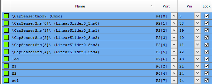
Finally I assign the pins:
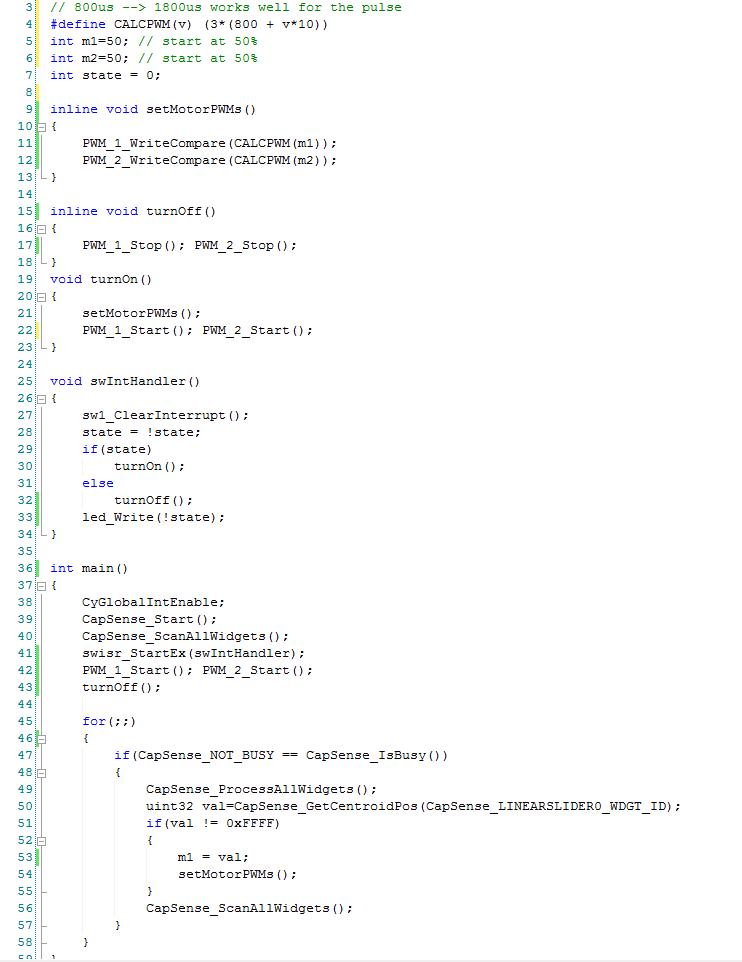
And a little bit of firmware:
Line 4 is a #define macro that calculate the correct compare value for the PWM. After a little bit of experimenting with the Robot I figured out that it really wants the PWM to range between 800 microseconds and 1.8 milliseconds.
Line 5-7 initialize the original position of the PWM
Line 15-19 and 19-23 are helper functions which just turn on and off the PWMs.
Line 25-34 is an interrupt handler that is trigger when the user presses the switch. It toggles a global state variable, turns on or off the PWMs and turns on/off the led.
In main I get things going on lines 38-43. Then start an infinite loop that reads the capsense, and if the value is set then I set the value for the PWMs. Remember that the capsense slider returns a value 0-100 so I can use it directly.
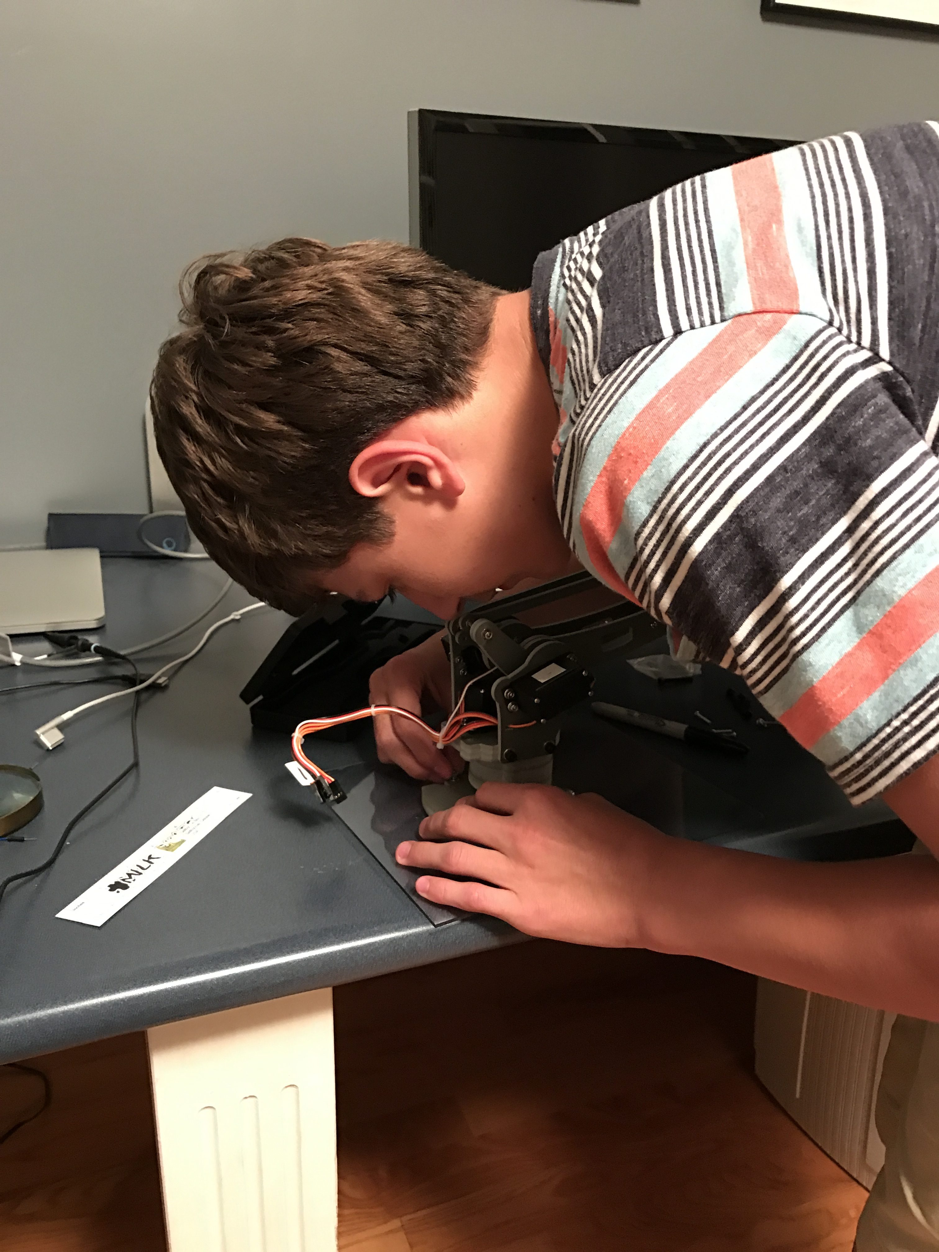
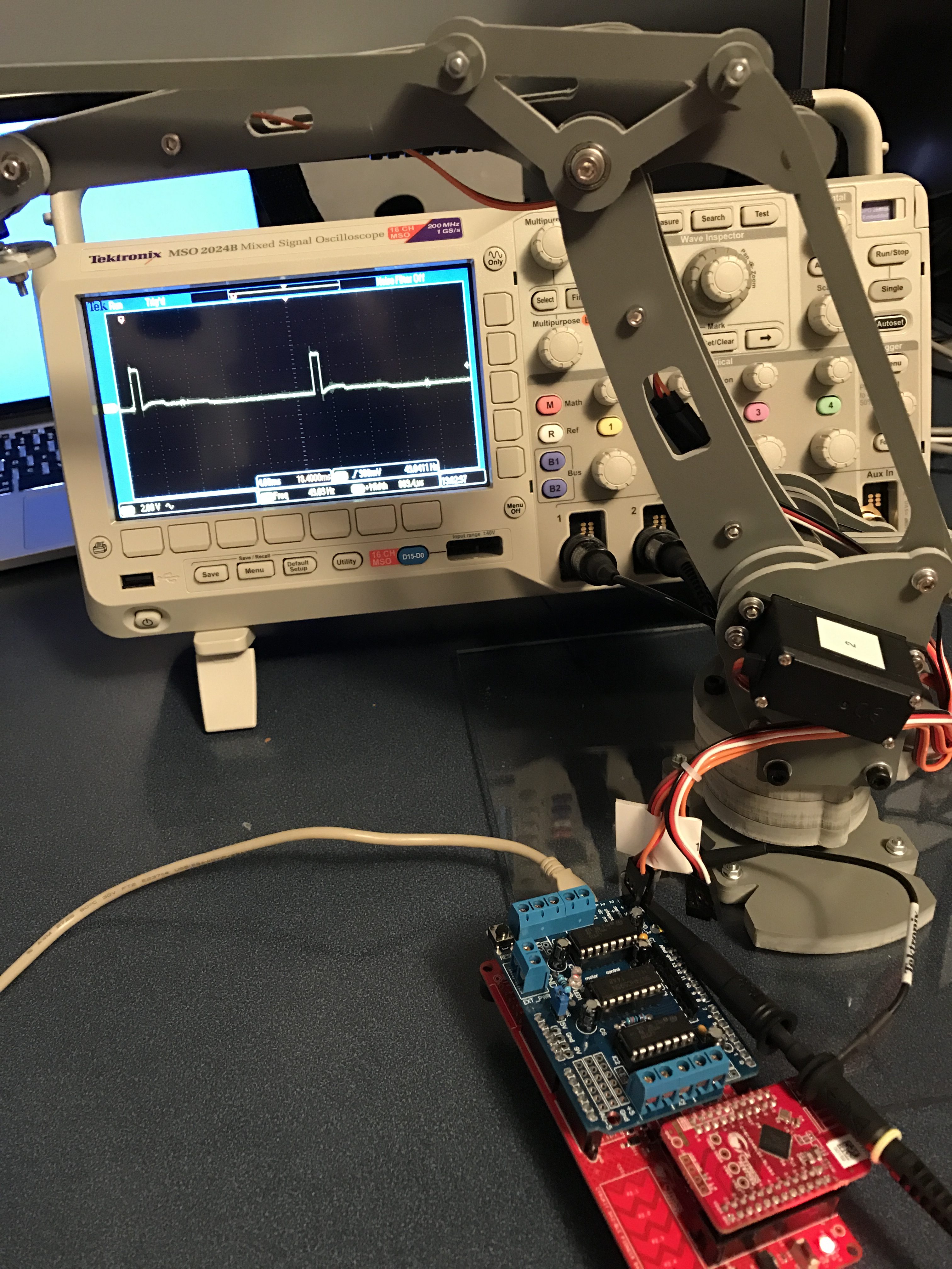
After all of that my lab technician once again test it:
No comment yet, add your voice below!