In the previous posts I introduced you to the Smart IO. I also went through the instructions to create CapSense Buttons using the new Mutual-cap CSX mode of the PSoC4000S. In this post I am going to use the three CapSense buttons on the CY8CKIT-145 as inputs to the Smart IO. I want to create a simple logic function P25 = !XOR(P24,P26,P27). This will cause the LED that is attached P25 to light up when there is an odd number of 1’s on P24,P26,P27. The equation is slightly strange because the LED is wired as active low (it lights up when there is a 0 written to it)
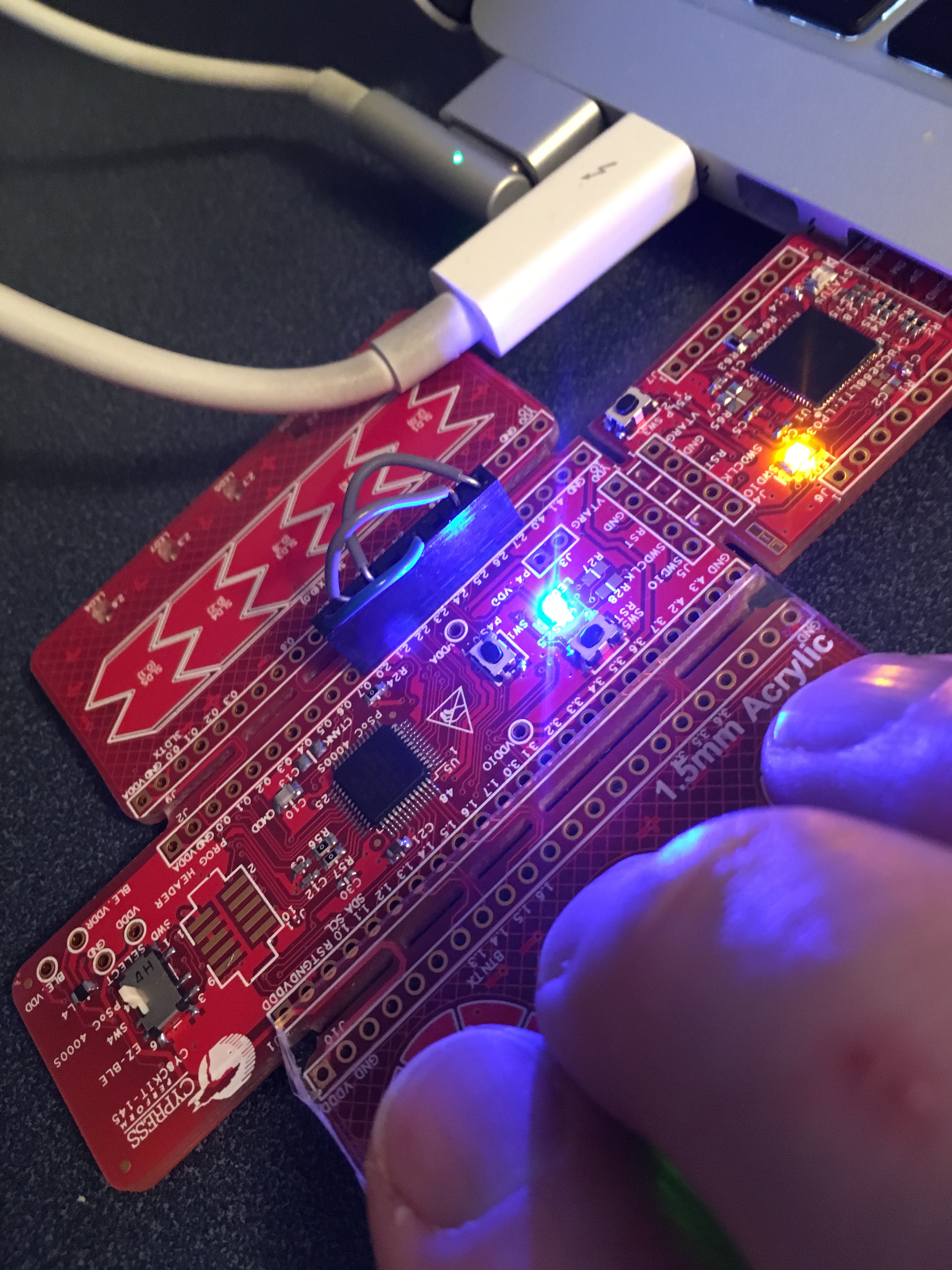
To make this work I soldered an 8 pin female header to Port 2 of my development kit. I then wired:
- P20 <–> P24
- P21 <–> P26
- P22 <–> P27
You can see all of that in the picture below.
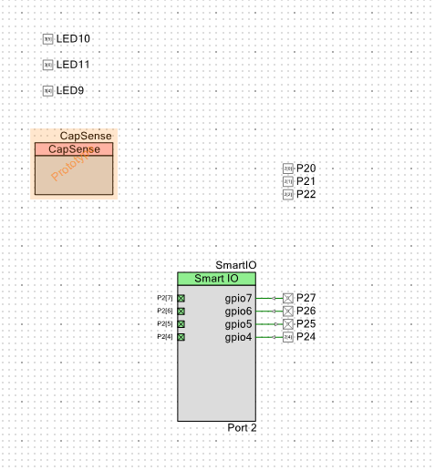
The next step is to create the schematic for this design. I started from the Mutual Capacitance project that I talked about in the previous post. It has three LEDs and the Capsense Buttons. I then add
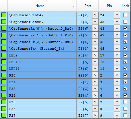
- Three digital output pins (P20,P21,P22) to drive the three inputs to the SmartIO
- Three digital input pins (P24,P26, P27) to use as inputs to the SmartIO
- One digital output pin (P25) to drive the LED
- The Smart IO block
The next step is to configure the SmartIO. I setup P24,P26,P27 as “inputs” and setup P25 as an “output”
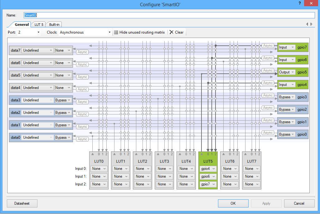
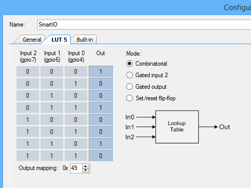
Then I configure the LUT to match the logic equation: P25 = !XOR(P24,P26,P27)
Lastly I assign the pins to the correct physical pins on the chip.
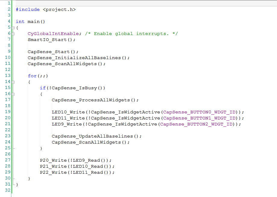
Then I create the firmware by copying the main.c from the earlier CapSense example. I then add the small amount of code to glue it all together:
- Line 7: start the SmartIO
- Lines 27-29: Write to P20,P21,P22 based on the state of the input buttons.
You can find this PSoC Creator workspace on github in the directory called “SmartIO”. This project is called “3Xor”.
In the next post I will show you how to make a state machine using the Smart IO.
Index
Description
PSoC4000s & The SmartIO – Part 1
An introduction to the SmartIO and first project
PSoC4000s & CSX Mutual CapSense Buttons Part 1
Using mutual capacitance
PSoC4000s & CSX Mutual CapSense Buttons Part 2
Using the CapSense tuner
PSoC4000s & The SmartIO – Part 2
A 3 input XOR logic gate
PSoC4000s & The SmartIO – Part 3
A 3 bit up counter state machine
PSoC4000s & The SmartIO – Part 4
Using an external clock with the Smart IO
PSoC4000s & The SmartIO – Part 5
Triggering an interrupt

4 Comments
Hi Alan, thanks for the examples of using SmartIO, it’s a great feature when using 4000S devices that (i think, correct me if i am wrong) does not have UDBs, or at least i could not find any logic gates on the component catalog.
Carlos
Correct. No UDBs. But the SmartIOs give you some logic… as a substitute in a very inexpensive device.
Thanks for the reply Alan.
I have been playing with the SmartIO and i’m unable to add a pull-up resistors on the digital input pins when it’s connected via HW to something else, for example the SmartIO gpio inputs or directly to a digital output.
I’m able to set the pull-ups when the HW Connection option is unchecked.
This is a device limitation? haven’t read the whole family datasheet tho :/.
Thank in advance, your write-ups are great 😀
I dont know.
Im traveling (the last three weeks)… but will figure it out when I get back this week.